Advertisement
Quick Links
DIXIE GRINDERS INC.
1324 RAILROAD AVENUE
GUNTERSVILLE, AL 35976
(800) 745-0586 (256) 582-0477 FAX (256) 582-0478
MODEL 11-7
GRINDER UNIT
CAUTION
THIS MANUAL MUST BE READ TO,
OR BY EACH PERSON, BEFORE
THAT PERSON OR DEPARTMENT
UNCRATES, OPERATES,
MAINTAINS, OR SUPERVISES USE
OF THIS MACHINE IN ANY WAY.
SAFETY INSTALLATION OPERATION MAINTENANCE
Advertisement

Related Manuals for DIXIE GRINDERS 11-7


Summary of Contents for DIXIE GRINDERS 11-7
- Page 1 DIXIE GRINDERS INC. 1324 RAILROAD AVENUE GUNTERSVILLE, AL 35976 (800) 745-0586 (256) 582-0477 FAX (256) 582-0478 MODEL 11-7 GRINDER UNIT CAUTION THIS MANUAL MUST BE READ TO, OR BY EACH PERSON, BEFORE THAT PERSON OR DEPARTMENT UNCRATES, OPERATES, MAINTAINS, OR SUPERVISES USE OF THIS MACHINE IN ANY WAY.
- Page 2 Dixie Grinders Inc. Double Plate Assembly. DIXIE GRINDERS INC. TRIPLE PLATE ASSEMBLY...
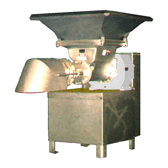
- Page 3 PLATE GUARD SAFETY TAG MOTOR COVER PANELS HEAD FRAME RING TYPICAL DIXIE 11-7 GRINDER UNIT LISTED BELOW IS THE DEFINITION OF THE HAZARD LEVEL USED ON THE SAFETY STICKERS. IMMEDIATE HAZARDS WHICH WILL RESULT IN SEVERE PERSONAL INJURY OR DEATH.
- Page 4 Dixie Grinders Inc. at once. (256) 582- 0477 OR (800) 745-0586. The primary grinding components are a plate retaining ring, orifice plate, plate bushing, This machine was sold for a specific application.
- Page 5 ACCESS TO THE PLATE, THE KNIFEHOLDER, AND THE FRONT END OF THE FEEDSCREW! REPLACE SAFETY TAGS WHEN NECESSARY! CALL DIXIE GRINDERS INC. FOR REPLACEMENT SAFETY TAGS. TAG D 1 EA. (ON GEARBOX) TAG C 2 EA. (ON FRONT OF HOPPER AND FRONT OF FRAME)
- Page 6 Dixie Grinders Inc. before unloading the machine! Platforms should be so designed not to make the hopper guard, or other guarding, UNLOADING GRINDER UNIT: ineffective.
- Page 7 We do not recommend remote operation of any grinder unit unless special precautions are taken, and that all possibilities of employee Dixie Grinders Inc. does not supply motor injury are eliminated. controls, starters, stop/start stations, disconnects, or other related equipment that is required to control the function of the grinder unit.
- Page 8 DISASSEMBLY TOOLS: Ring Wrench / Worm insertion tool If the grinder is not located on floor level The Ring Wrench fits over the lugs of ring and make no attempt to disassemble the grinder is used to loosen the ring (counter clockwise), unit without an adequate platform or or tighten the ring (clockwise) provisions provided by the installation...
- Page 9 Dropping the ring on the end of the pin will GRINDER UNIT DISASSEMBLY: damage the threads each and every time. There is no maybe, the threads are damaged and they READ AND UNDERSTAND THE need to be fixed. Trying to screw a damaged FOLLOWING TAG.
- Page 10 Step 4 continued, removing 2nd knifeholder. Step 3 continued. It may be necessary to wiggle or rock the plate in order to remove Step 5. Remove the 2nd set of washer springs, #2578. Step 4. Remove the 2nd knifeholder, #2441. The #2440 inserts are sharp so be carefull.
- Page 11 Step 7. Remove the chamber ring, #D2577. The chamber ring is heavy. Get help, and be careful. Do not drop the chamber ring on the centering pin. Dropping the chamber on the centering pin will put a flat spot on the threads that must be removed before the chamber ring can be used again.
- Page 12 Step 8 continued. Remove the first plate, #1114 X 1/4". The first bushing #10031 slides into the plate from the back side. Notice the recess in the face of the knifeholder that provides clearance for the Step 10. The hand is removing the #10035 bushing.
- Page 13 It may be necessary to hold the feedscrew in while pulling the pin out. The pin and pin hole should be cleaned Step 12. Remove the pin, #10030, notice daily. If the pin is not removed on a regular how the #10010-1 pin key was caught basis the pin will become seized and you will with the other hand! never get it out!
- Page 14 Be careful, the feedscrew has sharp corners that can cut, the cupping is sharp! Wear appropriate safety equipemnt and remember to always "Work Safely". With the feedscrew removed from the grinder unit, it can now be wired. Dixie Grinders Inc. does not supply motor controls, disconnects, or stop/start stations. Please consult your Electrical...
- Page 15 Check label instructions before using. If you notice that the tin plating is coming off of your grinder unit contact Dixie Grinders Inc. UNIT ASSEMBLY: Please study all of the grinder parts shown on the exploded view before you attempt to assemble the grinder unit.
- Page 16 The head space should be checked on a weekly basis. The head space is 3/4" on all DGI grinder units. This should be done with the excluder seal removed. Spacers should be added if the measurement is more than 3/4". Spacers should be removed if less than 3/4".
- Page 17 UNIT ASSEMBLY: Please study all the grinder parts shown on the exploded view before you attempt to assemble the grinder unit. (The exploded view follows the Maintenance section.) (These instructions assume that the grinder unit has not been disassembled any further than the instructions have already given.) Step 1.
- Page 18 Step 4. INSTALL FEEDSCREW. Step 5. INSTALL CENTERING PIN. Using the Model FSP2001 feedscrew puller, Check adjustment bolt to make sure it is in or other device, install the feedscrew into the the pin. The pin is supplied with four grinder unit.
- Page 19 Step 7. Install the #10035 springs. Note, these are the springs with the larger hole. #2578 3.125 OD X 1.563 ID #10035 3.125 OD X 1.905 ID This set of springs provides 3/16" of travel.
- Page 20 Insert locating pin. Use a soft mallet, a block of soft wood or soft plastic to tap the inserts in place. Do not use a steel faced hammer! Step 7 continued, installing #10035 springs. Check the knifeholder for flatness after the inserts are installed, it should not rock.
- Page 21 Step 10. Inspect the Orifice Plate. Obviously the Double Plate Assembly means that the grinder has two sets of plates, Step 8 continued. Install the knifeholder. knifeholders, springs, and bushings. The plates work together as a team, each plate has a specific function.
- Page 22 Grinder Plates should be sharpened with a vertical type surface grinder, typically called a "Blanchard Type". With this type of surface grinder the plate should be placed directly over the center of the table. We do not recommend sharpening the plates when they are placed out on the table, not directly over the center of the table.
- Page 23 Step 11. Install the bushing into the plate, then install plate and bushing into the grinder. Notice that the bushing rim faces inward. Inspect the bore flutes. Notice that this chamber ring has 19 flutes. The corners of the flutes should be sharp. The chamber and the impeller work together to force the product through the next plate.
- Page 24 When the ring is tightened, back it off 1/8 to 1/4 turn. Step 14. Inspect the #10026 impeller. The square should fit the pin snug. The four pressure flights should be flat and straight. Excessive wear has an effect on how your machine performs.
- Page 25 Step 16. Install the #2578 springs, one cup facing in, the second facing out. Step 17. Replace the #2440 inserts in the #2441 four bladed knifeholder. Again check the insert locating pins. Again check to make sure that the knifeholder is not rocking. If you can slide Note that this set of springs also provides more than a piece of folded paper under the 3/16"...
- Page 26 Step 20. Inspect the #10163 bushing. It should be free of nicks and burrs. When new, it measures 1.510, throw it away at 1.545! Install the bushing in the plate and lubricate generously. Step 18. Install the #2441 knifeholder. Step 21. Install the well lubricated plate and Step 19.
- Page 27 The threads of the ring should be inspected before the ring is assembled on the head. The threads must be perfectly clean, and free of Step 22. Inspect the ring, #10027. any nicks or burrs. If there are nicks or burrs they must be removed or the ring and head may lock together.
- Page 28 NOTE: YOUR GRINDER MAY USE AN INNER RING, TRANSITION FUNNEL, AND OUTER RING INSTEAD OF THE When the ring is tightened, back it off 1/8 to RING AND PLATE GUARD SHOWN IN 1/4 turn. It may be necessary to hold the last THIS MANUAL.
- Page 29 OPERATING INSTRUCTIONS. The grinder unit should never be left unattended while running. If you have to be away from your work station, turn the grinder off. If for any reason the grinder has to be taken apart, the POWER SHOULD BE LOCKED OUT! We recommend a strict policy that states "Touching the grinder...
- Page 30 OPERATING INSTRUCTIONS continued. Never operate a grinder unit while under the The hopper guard is a guard, not a large influence of alcohol or drugs. capacity chute or storage bin. Large pieces of fresh meat do not bridge as easily as pre- Do not place your hands under the plate ground material, but the grinder cuts the guard for any reason.
- Page 31 .500 -.002 The orifice plate is probably the most important single piece of a meat grinder. Dixie Grinders Inc. sells only "PREMIUM" type tool steel plates. Extensive testing has shown time and time again that our selection of tool steel performs the best over the entire range of products ground.
- Page 32 These plates allow our customers an increase A majority of all service calls eventually of up to 100 pounds per minute in some point to the customers real problem, dull applications. When combined with the "Thin plates. Next to plate sharpness, plate flatness Plate"...
- Page 33 When grinding plates, do not place the plate Examine the grinder plate for cracks before at the outer edge of the surface grinder table. each sharpening. If tramp metal has been ground, examine the plate very carefully. A plate that is free of cracks will have a distinctive ring if struck with a small metal rod.
- Page 34 CENTERING PIN. SPRINGS. The pin must be removed daily for The washer springs last a very long time. sanitation. The vent slot should be clean, They are designed to last for about five and free of obstruction. The small million cycles, so it is doubtfull they will ever diameter that the bushing runs on is the wear out.
- Page 35 If the inserts are removed incorrectly these pins can be broken. Send your knifeholder with broken pins to Dixie Grinders Inc. for repair. Examine the knife inserts. The edge of the insert should be free of burrs, Be carefull,...
- Page 36 If you do not have the equipment to sharpen your plates, or you do not know if they are being sharpened properly, send them to Dixie Grinders Inc. (attention Service Department) and we will examine your plate, sharpen it properly, and return it to you...
- Page 37 HEAD. The heads have three different types of flutes. The bore flutes, the spin flutes, and the spin lugs. The bore flutes are the spiral flutes that extends for about 15". The spin flutes are the flutes that are on the tapered section. The spin lugs are the flutes behind the plate.
- Page 38 FEEDSCREW. Foreign metal has obviously damaged this feedscrew. This type of damage makes this feedscrew unfit for use. Other than the tramp metal damage, this feedscrew has sufficient wear to make it unusable. The outside diameter of the pressure flights are rounded. They should have a square edge. The front of the pressure flight should be flat.
- Page 39 Examine the flights in the head section. Notice how the corners are rounded. The flighting should be replaced when it is worn down to 3/8" thick. Also notice the crack at the root of the shaft. There is so much wear of the weld that holds the flighting to the shaft that it is prone to cracking.
- Page 40 Note the sharp corners and square edges on Sharp cupping is needed to aggressively a new feedscrew. grasp the product that falls into the hopper. On a new or rebuilt feedscrew you will notice that the flighting is thicker. When new or rebuilt, the corners are square.
- Page 41 HOPPERS. Tin plated hopper wth new safety stickers. The spin ridge, which runs the length of the hopper at the bottom, should have a square corner. When this edge becomes rolled over, the feedscrew has difficulty feeding the head correctly. In time, the excluder seal will wear a ridge in the back flange of the hopper.
Need help?
Do you have a question about the 11-7 and is the answer not in the manual?
Questions and answers