Advertisement
Quick Links
DIXIE GRINDERS INC.
1324 RAILROAD AVENUE
GUNTERSVILLE, AL 35976
(800) 745-0586 (256) 582-0477 FAX (256) 582-0478
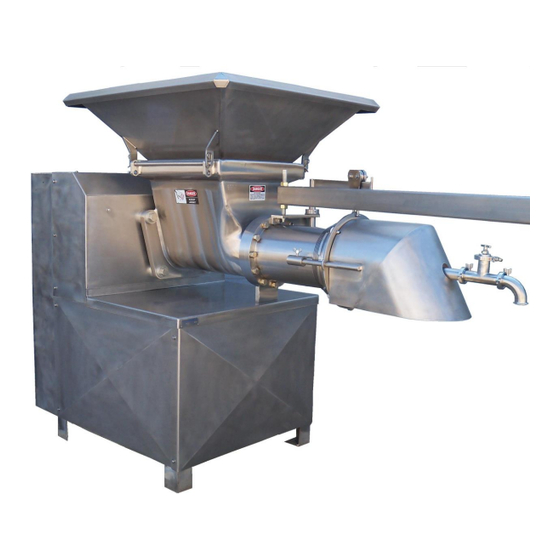
MODEL 12-10
GRINDER UNIT
CAUTION
THIS MANUAL MUST BE READ TO,
OR BY EACH PERSON, BEFORE
THAT PERSON OR DEPARTMENT
UNCRATES, OPERATES,
MAINTAINS, OR SUPERVISES USE
OF THIS MACHINE IN ANY WAY.
SAFETY INSTALLATION OPERATION MAINTENANCE
Advertisement

Subscribe to Our Youtube Channel
Related Manuals for DIXIE GRINDERS 12-10


Summary of Contents for DIXIE GRINDERS 12-10
- Page 1 DIXIE GRINDERS INC. 1324 RAILROAD AVENUE GUNTERSVILLE, AL 35976 (800) 745-0586 (256) 582-0477 FAX (256) 582-0478 MODEL 12-10 GRINDER UNIT CAUTION THIS MANUAL MUST BE READ TO, OR BY EACH PERSON, BEFORE THAT PERSON OR DEPARTMENT UNCRATES, OPERATES, MAINTAINS, OR SUPERVISES USE OF THIS MACHINE IN ANY WAY.
- Page 2 HOPPER SAFETY TAG ORIFICE PLATE GUARD MOTOR COVER SERIAL FRAME PANELS NUMBER TYPICAL DIXIE 12-10 GRINDER UNIT LISTED BELOW IS THE DEFINITION OF THE HAZARD LEVEL USED ON THE SAFETY STICKERS. IMMEDIATE HAZARDS WHICH WILL RESULT IN SEVERE PERSONAL INJURY...
- Page 3 If for any reason you believe these meat by-products, and other similar products. guards are not adequate, do not use the machine and call Dixie Grinders Inc. at once. (256) 582- The primary grinding components are a plate 0477 OR (800) 745-0586.
- Page 4 PROVIDED TO RESTRICT ACCESS TO THE PLATE, THE KNIFEHOLDER, AND THE FRONT END OF THE FEEDSCREW! REPLACE SAFETY TAGS WHEN NECESSARY! CALL DIXIE GRINDERS INC. FOR REPLACEMENT SAFETY TAGS. 4.84B TAG D 1 EA. (ON GEARBOX) 12-10 14-014 TAG C 2 EA. (ON FRONT OF...
- Page 5 Dixie Grinders Inc. before unloading the machine! Platforms should be so designed not to make the hopper guard, or other guarding, ineffective.
- Page 6 Dixie Grinders Inc. does not supply motor controls, starters, stop/start stations, disconnects, or other related equipment that is required to control the function of the grinder...
- Page 7 DISASSEMBLY TOOLS: GRINDER UNIT DISASSEMBLY: If the grinder is not located on floor level make no attempt to disassemble the grinder READ AND UNDERSTAND THE unit without an adequate platform or FOLLOWING TAG. provisions provided by the installation contractor, plant engineer, or plant safety officer.
- Page 8 Step 6. REMOVE THE Step 3. PLATE REMOVAL: CENTERING PIN Using the plate lifter, remove the plate and bushing from the grinder unit. It is necessary to lift while pulling on the bushing. Do not use screwdrivers or other tools to pry the plate from the grinder unit.
- Page 9 MODEL FSP2006 FEEDSCREW PULLER With the feedscrew removed from the grinder unit, it can now be wired. Dixie Grinders Inc. does not supply motor controls, disconnects, or stop/start stations. Please consult your Electrical Engineer, your Safety Engineer, OSHA, and other Federal, State, and local...
- Page 10 OUT THE POWER! instructions before using. If you notice that the tin plating is coming off of your grinder unit contact Dixie Grinders Inc. UNIT ASSEMBLY: Please study all of the grinder parts shown on the exploded view before you attempt to assemble the grinder unit.
- Page 11 When using the ring wrench to install the feedscrew, lift the feedscrew slightly while pushing it in. If the feedscrew does not slide up on the spline, it may be necessary to push down and in, while turning the feedscrew slightly to engage the drive spline.
- Page 12 UNIT ASSEMBLY: Please study all the grinder parts shown on the exploded view before you attempt to assemble the grinder unit. (The exploded view follows the Maintenance section.) (These instructions assume that the grinder unit has not been disassembled any further than the instructions have already given.) Step 1.
- Page 13 Step 4. INSTALL FEEDSCREW. Step 5. INSTALL CENTERING PIN. Inspect the pin to make sure it is clean and Using the Model FSP2006 feedscrew puller, free of nicks and burrs. Replace the pin or other device, install the feedscrew into the when it shows wear grooves, checks, or is grinder unit.
- Page 14 Step 7. REPLACE INSERTS Inserting the pointed end of our insert remover into the slot of the knifeholder In the above illustration notice that the face provides a quick and easy way to remove the at the outer diameter of the first spring is knife inserts.
- Page 15 We recommend that a fresh plate surface should be used every 8 hours of operation. Operations that run empty or with hard to grind materials may have to change plate surfaces every 4 hours. Grinder Plates should be sharpened with a vertical type surface grinder, typically called a "Blanchard Type".
- Page 16 Step 12. INSTALL PLATE AND BUSHING INTO GRINDER UNIT. Step 10. INSPECT THE PLATE BUSHING. The plate bushing should be clean, and free of Slide the orifice plate with the plate bushing nicks and burrs. Inspect the inside diameter, installed over the end of the grinder pin. Lift it is common to show wear because the the end of the plate lifter handle and push the bushing supports the weight of the feedscrew.
- Page 17 Step 14. INSPECT THE RING The ring can weigh up to 65 pounds, if this is The threads of the ring should be inspected more than you can comfortably lift, get help. before the ring is assembled on the head. If you have a ring remover, use it.
- Page 18 OPERATING INSTRUCTIONS. The grinder unit should never be left unattended while running. If you have to be away from your work station, turn the grinder off. If for any reason the grinder has to be taken apart, the POWER SHOULD BE LOCKED OUT! We recommend a strict policy that states "Touching the grinder...
- Page 19 OPERATING INSTRUCTIONS continued. Never operate a grinder unit while under the The hopper guard is a guard, not a large influence of alcohol or drugs. capacity chute or storage bin. Large pieces of fresh meat do not bridge as easily as pre- Do not place your hands under the plate ground material, but the grinder cuts the guard for any reason.
- Page 20 -.002 The orifice plate is probably the most important single piece of a meat grinder. Dixie Grinders Inc. sells only "PREMIUM" type tool steel plates. Extensive testing has shown time and time again that our selection of tool steel performs the best over the entire range of products ground.
- Page 21 These plates allow our customers an increase A majority of all service calls eventually of up to 100 pounds per minute in some point to the customers real problem, dull applications. When combined with the "Thin plates. Next to plate sharpness, plate Plate"...
- Page 22 When grinding plates, do not place the plate Examine the grinder plate for cracks before at the outer edge of the surface grinder table. each sharpening. If tramp metal has been ground, examine the plate very carefully. A plate that is free of cracks will have a distinctive ring if struck with a small metal rod.
- Page 23 CENTERING PIN. SPRINGS. The pin must be removed daily for The washer springs last a very long time. sanitation. The vent slot should be clean, They are designed to last for about five and free of obstruction. The small diameter million cycles, so it is doubtfull they will ever that the bushing runs on is the only place wear out.
- Page 24 If the inserts are removed incorrectly these pins can be broken. Send your knifeholder with broken pins to Dixie Grinders Inc. for repair. Examine the knife inserts. The edge of the insert should be free of burrs, Be carefull,...
- Page 25 Line the notch of the insert up with the pin in The combination of the insert slot angle and the bottom of the slot of the knifeholder. If the angle that the inserts are ground provide necessary tap the insert into position with a that only the leading edge of the knife insert soft mallet, a soft rubber hammer, or a piece contacts the plate.
- Page 26 HEAD. Compare the picture of the new head to this worn head, the flutes should be sharp, not rounded. The edges of the flutes should have a square corner. When they become rounded the head should be rebuilt. Bore flute wear can be measured with our head guage. The wear limit depends on your application.
- Page 27 FEEDSCREW. Foreign metal has obviously damaged this feedscrew. This type of damage makes this feedscrew unfit for use. Other than the tramp metal damage, this feedscrew has sufficient wear to make it unusable. The outside diameter of the pressure flights are rounded. They should have a square edge. The front of the pressure flight should be flat.
- Page 28 Examine the flights in the head section. Notice how the corners are rounded. The flighting should be replaced when it is worn down to 3/8" thick. Also notice the crack at the root of the shaft. There is so much wear of the weld that holds the flighting to the shaft that it is prone to cracking.
- Page 29 Note the sharp corners and square edges on a Sharp cupping is needed to aggressively new feedscrew. grasp the product that falls into the hopper. On a new or rebuilt feedscrew you will notice that the flighting is thicker. When new or rebuilt, the corners are square.
- Page 30 HOPPERS. Tin plated hopper wth new safety stickers. The spin ridge, which runs the length of the hopper at the bottom, should have a square corner. When this edge becomes rolled over, the feedscrew has difficulty feeding the head correctly. In time, the excluder seal will wear a ridge in the back flange of the hopper.
- Page 31 This grinder is equipped with our Ring Remover. This device aids in the installation and removal of the grinder ring. Inspect the Delrin wheels for damage before each use. Acorn nuts should be tight, hasp pin in position. The Ring Lift should support ring so no lifting is required.
- Page 32 The feedscrew puller is a great aid in the installation and removal of the grinder feedscrew. it works great when adjusted properly. if it is out of adjustment it should not be used. The feedscrew puller can be adjusted easily with the use of a level. Place the level on the grinder head, then on the beam.
- Page 33 To aid in easy cleaning, this model is equipped with our enclosed gearbox framing. The gearbox is isolated from the grinder hopper by the 1-1/8" space shown, two seals are mounted in the adapter plate, one keeps the oil in the gearbox, the other keeps contaminates out of the gearbox.
Need help?
Do you have a question about the 12-10 and is the answer not in the manual?
Questions and answers