Table of Contents
Advertisement
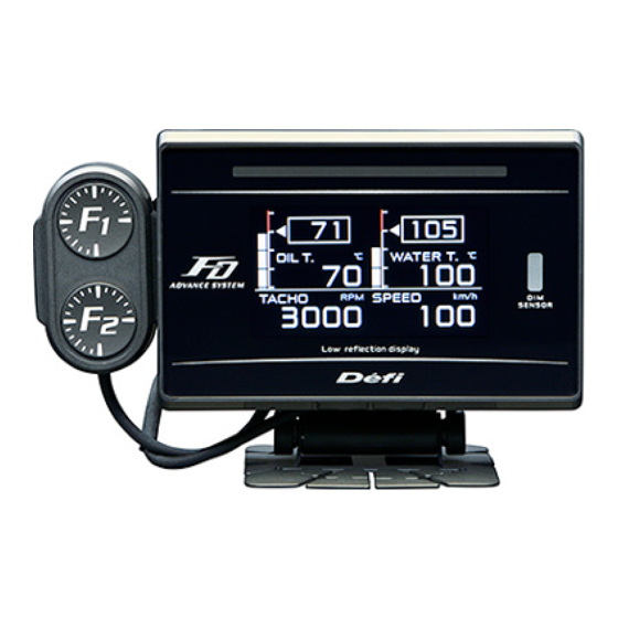
Defi-Link Meter ADVANCE FD Operation Manual
DF17801
Thank you very much for purchasing our product. Before installing and using the product,
please read this manual thoroughly. All sections are for customers and installation
personnel.
Defi will not be held responsible for accidents or damages related to installation of this
product.
ADVANCE FD Manual
1
Return to top
Advertisement
Table of Contents


Need help?
Do you have a question about the ADVANCE FD and is the answer not in the manual?
Questions and answers