
Related Manuals for Next Level Racing GT ELITE


Summary of Contents for Next Level Racing GT ELITE
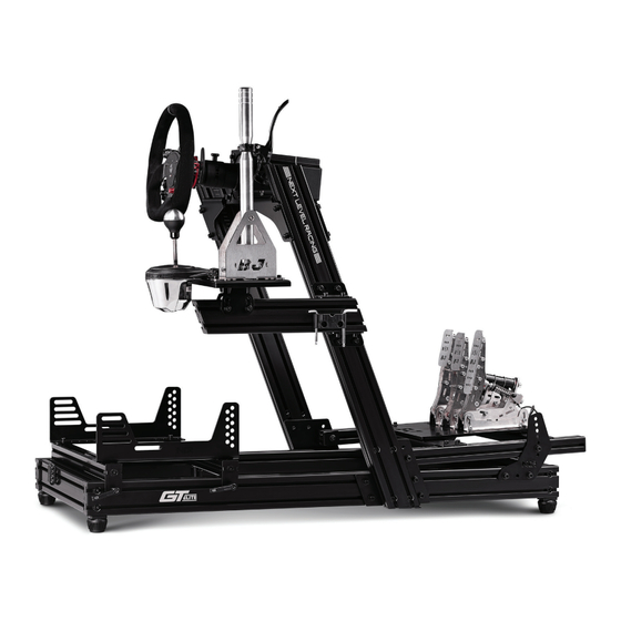
- Page 1 T A K E R A C I N G T O T H E N E X T L E V E L® Video Instruction: bit.ly/nlrbuild INSTRUCTION MANUAL *ELECTRONICS NOT INCLUDED...
- Page 2 T O T H E N E X T L E V E L® instruction booklet to fully optimize your product. N E X T L E V E L R A C I N G . C O M ASSEMBLY VIDEO bit.ly/nlrbuild @next_level_racing @nextlevelracingOfficial @nextlvlracing Next Level Racing FOLLOW support@nextlevelracing.com...
- Page 3 Video Instruction: bit.ly/nlrbuild support@nextlevelracing.com PRE-RACE IN THE CHECKS *NOT TO SCALE WARNING • Please do not use power tools for assembly as over tightening can damage your frame. • If you require further support, consult the installation video or contact us at support@nextlevelracing.com •...
- Page 4 Video Instruction: bit.ly/nlrbuild support@nextlevelracing.com 48 x M8 16mm BOLTS SEAT BRACKETS PEDAL ADJUSTMENT FINS 16 x M6 16mm BOLTS 12 x M8 20mm BOLTS 8 x M8 35mm BOLTS 8 x M8 40mm BOLTS 4 x M8 16mm COUNTERSUNK BOLTS 74 x M8 WASHERS MOUNTING ARMS 2 X UPRIGHT CONNECTION PLATES...
- Page 5 Video Instruction: bit.ly/nlrbuild support@nextlevelracing.com ALUMINIUM EXTRUSION TIPS • Please do not use power tools for assembly as over tightening can damage your frame. • Please ensure T-Nuts are correctly placed within the extrusion. • Lay out and build the cockpit on a level surface. •...
- Page 6 Video Instruction: bit.ly/nlrbuild support@nextlevelracing.com PARTS: FRONT • • 4 x M8 45mm Bolts • • 4 x M8 Washers RIGHT REAR FRONT LEFT Align the threaded holes on the Front and Rear Base Members with the pre-drilled holes on the Right Base Member.
- Page 7 Video Instruction: bit.ly/nlrbuild support@nextlevelracing.com PARTS: PARTS: • • 4 x T-Nuts • • Upright Connection Plates Note: Recess holes facing outward. • • 4 x Adjustable Feet • • 8 x M8 35mm Bolts Note: Parts are labelled for • • 8 x M8 Washers left and right side application Note: Height of the foot can be adjusted only when it’s installed on to the cockpit.
- Page 8 Video Instruction: bit.ly/nlrbuild support@nextlevelracing.com PARTS: PARTS: • • 8 x M8 T-Nuts • • Side Mount Brackets • • 4 x M8 14mm Low Profile Bolts Repeat on Other Side • • 4 x M8 Nylon Washers Install 2 x T-Nuts into the front channel and 2 x T-Nuts into the back channel of the Left Vertical Post. A) Align the Side Mount Brackets holes with the threaded inserts on the Front Mount Brackets.
- Page 9 Video Instruction: bit.ly/nlrbuild support@nextlevelracing.com PARTS: PARTS: SIDE MOUNT ANGLE ADJUSTMENT SIDE MOUNT ASSEMBLY • • Spacer Plates • • NIL • • 4 x M8 20mm Countersunk Bolts A) Align the holes on the Spacer Plates with the mounting holes on the Wheel Base. Loosen the Bolts securing the Wheel Base assembly to the Side Mount Brackets.
- Page 10 Video Instruction: bit.ly/nlrbuild support@nextlevelracing.com PARTS: PARTS: ALTERNATE PEDAL INSTALLATION SIDE VIEW Repeat TOP VIEW • • 8 x M8 T-Nuts on Other • • 2 x M8 20mm Bolts FOR SHORTER USERS Side PRE-DRILLED HOLE • • 2 x M8 Washers LEFT PRE-DRILLED HOLE RIGHT...
- Page 11 Video Instruction: bit.ly/nlrbuild support@nextlevelracing.com PARTS: PARTS: PEDAL ADJUSTMENT RANGE • • NIL • • 6 x T-Nuts • • 4 x Seat Sliders End Plates • • 4 x M8 16mm Countersunk Bolts • • 4 x Sticky Felt Pads (35mm x 40mm) Butt-Kicker T-Nut Locations A) Install 2 x T-Nuts into the bottom channel of the Front Seat Slider Member for the Buttkicker Mount Pole.
- Page 12 Video Instruction: bit.ly/nlrbuild support@nextlevelracing.com PARTS: PARTS: Repeat OVER-HANGING SEAT BRACKET on Other • • Seat Brackets • • 4 x M8 16mm Bolts Side FOR TALLER USERS • • 4 x M8 Washers SIDE VIEW Align the first rear slot on the Seat Brackets with the T-Nuts previously installed in STEP 22. Bolt Align the Seat Brackets with the T-Nuts previously installed in STEP 22.
- Page 13 Video Instruction: bit.ly/nlrbuild support@nextlevelracing.com PARTS: PARTS: • • 1 x Shifter Mounting Corner • • 4 x T-Nuts Brackets • • 2 x M8 16mm Bolts • • 2 x M8 Washers Align the slots on the bottom Shifter Mounting Corner Bracket with the T-Nuts previously installed in Install 2 x T-Nuts into the top channel and 2 x T-Nuts into the bottom channel of the Shifter Arm.
- Page 14 Video Instruction: bit.ly/nlrbuild support@nextlevelracing.com PARTS: PARTS: • • 2 x M8 16mm Bolts • • 2 x M8 16mm Bolts • • 2 x M8 Washers • • 2 x Nylon Washers Align the holes on the Tool Kit Holder with the T-Nuts previously installed in STEP 31a. Bolt through and secure Align the T-Nuts previously installed into the Shifter Arm in STEP 31b with the holes on the bottom Shifter Arm with M8 Bolts and Nylon Washers.
- Page 15 Video Instruction: bit.ly/nlrbuild support@nextlevelracing.com NOTES WARNING Please do not use power tools for assembly as over tightening can damage your frame. If you require further support, consult the installation video or contact us at support@nextlevelracing.com Please ensure T-Nuts are correctly placed within the extrusion. Lay out and build the cockpit on a level surface.
- Page 16 14c - Se référer à l’image. Alignez les trous de l’assemblage de l’empattement avec les trous de montage des supports de montage latéraux. Boulonnez et fixez avec 4 boulons à profil bas M8 et des rondelles en NEXT LEVEL RACING® Manuel d’instructions pour montage frontal et latéral GTElite nylon.
- Page 17 NEXT LEVEL RACING® Instructiehandleiding GTElite voor- en zijmontage 14c - Zie afbeelding. Lijn de gaten op de wielbasis uit met de montagegaten op de zijmontagebeugels. Schroef door en zet vast met 4 x M8-bouten met laag profiel en nylon ringen.
- Page 18 NEXT LEVEL RACING® Manuale di istruzioni per montaggio frontale e laterale GTElite 14c - Fare riferimento all’immagine. Allineare i fori sul gruppo della base della ruota con i fori di montaggio sulle staffe di montaggio laterali. Avvitare e fissare con 4 bulloni a basso profilo M8 e rondelle in nylon.
- Page 19 NEXT LEVEL RACING® Manual de instrucciones de montaje frontal y lateral de GTElite 14c - Consulte la imagen. Alinee los orificios del conjunto de la base de la rueda con los orificios de montaje de los soportes de montaje lateral. Atornille y asegure con 4 pernos de perfil bajo M8 y arandelas de ¡Sabemos que estás ansioso por empezar a correr! Tómese su tiempo con las instrucciones y siga esta guía para ensamblar su producto.
- Page 20 14d - Siehe Bild. Lösen Sie die Schrauben, mit denen die Radträgerbaugruppe an den seitlichen Halterungen befestigt ist. Stellen Sie den gewünschten Winkel ein und ziehen Sie die Schrauben fest, um sie zu NEXT LEVEL RACING® Bedienungsanleitung für GTElite Front- und Seitenmontage verriegeln.
- Page 21 Video Instruction: bit.ly/nlrbuild support@nextlevelracing.com NEXTLEVELRACING® GTEliteフロント&サイドマウント取扱説明書 14c-画像を参照してください。 ホイールベースアセンブリの穴をサイドマウントブラケットの取り付け穴に合わせます。 4 xM8ロープロファイルボルトとナイロンワッシャーでボルトで固定します。 あなたがレースを始めたいと思っていることを私たちは知っています !指示に従って時間をかけて、 このガイドに従って製品を組み立ててください。 取扱説明書に従って製品を完全に最適化することで、 成功への準備を整え 14d-画像を参照してください。 ホイールベースアセンブリをサイドマウントブラケットに固定しているボルトを緩めます。 希望の角度に調整し、 ボルトを締めて所定の位置に固定します。 ることができます。 組み立てビデオの場合は、 QRコードをスキャンします。 bit.ly/nlrbuild。 フォローする。 QRコードをスキャンする 14e-画像を参照してください。 サイドマウントブラケットをマウンティングアームに固定しているボルトを緩めます。 希望の位置に調整し、 ボルトを締めて所定の位置に固定します。 14f-画像を参照してください。 取り付けアームを垂直支柱に固定しているボルトを緩めます。 希望の位置に調整し、 ボルトを締めて所定の位置に固定します。 警告 15a-画像を参照してください。 左ペダルアームの上部チャネルに3x Tナットを取り付け、 側面チャネルに1 xTナットを取り付けます。 右ペダルアームについても同じ手順を繰り返します。 •締めすぎるとフレームが損傷する可能性があるため、...
- Page 22 NEXT LEVEL RACING® Manual de instruções de montagem frontal e lateral GTElite 14c - Consulte a imagem. Alinhe os orifícios no conjunto da base da roda com os orifícios de montagem nos suportes de montagem lateral. Aparafuse e prenda com 4 parafusos de baixo perfil M8 e arruelas de Sabemos que você...
- Page 23 14d - См. Изображение. Ослабьте болты, которыми колесная база в сборе крепится к боковым монтажным кронштейнам. Установите желаемый угол и затяните болты, чтобы зафиксировать их на месте. NEXT LEVEL RACING® Руководство по эксплуатации GTElite для фронтального и бокового монтажа 14e - См. Изображение. Ослабьте болты, которыми боковые монтажные кронштейны крепятся к монтажным рычагам. Установите желаемое положение и затяните болты, чтобы зафиксировать их на...
- Page 24 Video Instruction: bit.ly/nlrbuild support@nextlevelracing.com NEXT LEVEL RACING® Elite Ön ve Yan Montaj Talimat Kılavuzu 14c - resme bakın. Tekerlek Tabanı aksamındaki delikleri Yan Montaj Braketlerindeki montaj delikleriyle hizalayın. 4 x M8 Düşük profilli Cıvatalar ve Naylon Pullar ile cıvatalayın ve sabitleyin.
- Page 25 Video Instruction: bit.ly/nlrbuild support@nextlevelracing.com NEXT LEVEL RACING® Návod k použití přední a boční montáže GTElite 14d - viz obrázek. Povolte šrouby zajišťující sestavu základny kola k bočním držákům. Nastavte požadovaný úhel a utáhněte šrouby, aby zapadly na místo. Víme, že toužíte začít závodit! Udělejte si čas s pokyny a podle tohoto průvodce sestavte svůj produkt. Budete se připravovat na úspěch, když budete postupovat podle návodu k plné optimalizaci svého produktu.
- Page 26 15b - Patrz rysunek. Dopasuj przelotowy otwór w ramieniu pedału do otworu w pionowej płytce łączącej. Przykręć i zabezpiecz śrubą M8, podkładką, podkładką kwadratową i nakrętką kołnierzową. Powtórz po drugiej stronie. NEXT LEVEL RACING® Instrukcja obsługi przedniego i bocznego montażu GTElite 16a - Patrz rysunek. Zamontuj 1 nakrętkę T w bocznym kanale ramienia pedału. Powtórz po drugiej stronie.
- Page 27 NEXT LEVEL RACING® ـل يبناجلاو يمامألا بيكرتلا تاميلعت ليلدGTElite 14 × 4 ريماسم مادختساب نمآو ماكحإب اهطب ر ا .ةيبناجلا تيبثتلا فئاتك ىلع ةدوجوملا بيكرتلا تاحتف عم تالجعلا ةدعاق ةعومجم يف ةدوجوملا تاحتفلا ةاذاحمب مق .ةروصلا ىلإ عوجرلا - جM8 .نوليانلا نم تالاسغو عافت ر الا ةضفخنم...
- Page 28 Video Instruction: bit.ly/nlrbuild support@nextlevelracing.com Next Level Racing® GTElite 正面和侧面安装说明手册 14d - 参考图像。松开将轮距组件固定到侧安装支架的螺栓。调整到所需的角度并拧紧螺栓以锁定到位。 我们知道您渴望开始比赛!花点时间阅读说明并按照本指南组装您的产品。遵循说明手册以全面优化您的产品,您将为成功做好准备。对于装配视频,扫描二维码。 bit.ly/nlrbuild。跟 14e - 参考图像。松开将侧面安装支架固定到安装臂的螺栓。调整到所需位置并拧紧螺栓以锁定到位。 着我们。扫描二维码 14f - 参考图像。松开将安装臂固定到垂直立柱的螺栓。调整到所需位置并拧紧螺栓以锁定到位。 15a - 参考图像。将 3 个 T 形螺母安装到顶部通道中,将 1 个 T 形螺母安装到左踏板臂的侧通道中。对右踏板臂重复相同的步骤。 警告 15b - 参考图像。将踏板臂上的通孔与立柱连接板上的孔对齐。用 M8 螺栓、垫圈、方垫圈和法兰螺母拧紧并固定。在另一边重复。 • 请不要使用电动工具进行组装,因为过度拧紧会损坏您的车架。...
- Page 29 support@nextlevelracing.com support@nextlevelracing.com...
Need help?
Do you have a question about the GT ELITE and is the answer not in the manual?
Questions and answers