Table of Contents
Advertisement
Quick Links
Advertisement
Table of Contents

Subscribe to Our Youtube Channel
Related Manuals for Dion-Ag F71


Summary of Contents for Dion-Ag F71
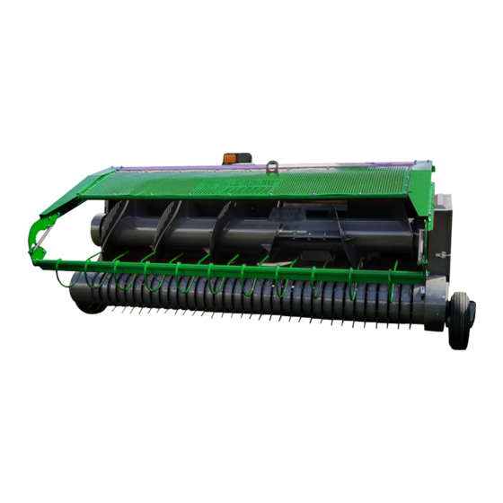
- Page 1 Operator’s Manual Hay Pick-Up Attachment Manual no. F7122E030...
- Page 2 Right to Make Design Changes – Dion-ag reserves the right to make changes in the design and other changes in its products at any time and from time to time without notice and without incurring any obligation of its part to modify, improve or add to products previously ordered from Dion-Ag and sold or shipped by Dion-Ag.
- Page 3 HAY PICK-UP ATTACHMENT TO OUR CUSTOMER We appreciate your confidence in DION Farm Equipment and thank you for your trust. In preparing this manual, we hope we have furnished you with a valuable tool for operating and maintaining this fine ma- chine.
-
Page 4: Table Of Contents
TABLE OF CONTENTS SPECIFICATIONS ................................SERIAL NUMBER LOCATION ............................CHECK LIST ..................................FOREWORD ..................................SAFETY RULES ................................SAFETY ALERT SYMBOL ..........................FOLLOW A SAFETY PROGRAM ........................A WORD TO THE OPERATOR ......................... SAFETY RULES SPECIFIC TO THIS MACHINE ....................PROCEDURES FOR STOPPING THE HAY PICK-UP ATTACHMENT ............GUARDS AND SHIELDS .......................... -
Page 5: Specifications
SPECIFICATIONS Specifications and design are subject to change without notice and without liability therefore. MODEL : ..................Hay Pick-up Attachment F71-108 WEIGHT AND DIMENSIONS: Weight ................... 1280 lbs (580 kg) Overall width .................. 131’’ (333 cm) Pick-up width ................. 108’’ (275 cm) Left &... -
Page 6: Serial Number Location
Always mention both the model and the serial numbers when ordering parts or regarding any other correspondence referring to your machine Write down your number here: MODEL NO. SERIAL NO. DION-AG INC. BOISBRIAND QUE. Dion-Ag Inc. MODEL NO. SERIAL NO. -
Page 7: Check List
CHECK LIST PRE-SEASON CHECKS Clean the Hay Pick-up Attachment, removing trash and dirt accumulation. Clean and inspect chains for excessive stiffness or wear Lubricate the machine according to the LUBRICATION chart. Make sure grease fittings are in place and taking grease properly Check to make sure the Pick-up Attachment is attached properly to the Forage Harvester. -
Page 8: Foreword
FOREWORD TO OUR CUSTOMER WARRANTY INFORMATION The following pages and illustrations are printed to help The warranty for this machine is located at the beginning supply you with the knowledge to better operate and of this manual. service your Hay Pick-up Attachment. If the Hay Pick-up is used with a Forage Harvester from Any piece of equipment needs, and must have a certain another manufacturer, the warranty is limited to the Hay... -
Page 9: Safety Rules
SAFETY RULES SAFETY ALERT SYMBOL FOLLOW A SAFETY PROGRAM For proper operation of a Hay Pick-up Attachment, you must be a qualified and authorized operator. To be qualified, you must read and understand the written instructions supplied in this Operator’s Manual, have training, and know the safety rules and regulations for the job. -
Page 10: Safety Rules Specific To This Machine
SAFETY RULES • Disengage the PTO and shut off engine before • Never lubricate or clean any part while the machine leaving the operator’s seat for refueling, lubricating or tractor engine is running. or adjusting the machine. • Keep hands and body out of hitch area when •... -
Page 11: Procedures For Stopping The Hay Pick-Up Attachment
SAFETY RULES STOPPING PROCEDURES No matter what type of machine is being used, it is extremely hazardous to perform any kind of maintenance work while the machine is running. Before cleaning, adjusting, or greasing, the following procedures should be followed to stop the attachment: 1. -
Page 12: Safety Sign Location
SAFETY SIGN LOCATION WARNING DANGER SHIELDS MISSING STAY CLEAN WHILE WARNING DO NOT OPERATE MACHINE IS RUNNING ALL GUARDS, SHIELDS AND DOORS SHOULD BE IN PLACE AND PROPERLY ÉVITER TOUT CONTACT SECURED BEFORE STARTING THE DO NOT OPEN WHILE AVEC LE MÉCANISME TRACTOR ENGINE. -
Page 13: Operation
OPERATION OPERATION TIPS WARNING: Before operating the Hay Pick-up Attachment, make sure that all safety rules are observed by people working with or near this machine. WARNING: Make sure that all guards or shields are in place and properly secured before starting the tractor engine. -
Page 14: Installing The Hay Pick-Up On The Forage Harvester
OPERATION INSTALLING THE HAY PICK-UP ON THE FORAGE BOLT TORQUE SPECIFICATIONS HARVESTER The table below gives correct torque values for bolts used Refer to the Forage Harvester’s operator manual. on the machine. Check tightness of bolts periodically. Replace hardware with the same grade bolt. NOTE: The front part of the grain bottom plate needs to be removed before harvesting hay. -
Page 15: Lubrication
LUBRICATION LUBRICATION CHART These symbols indicate the specific points which must be lubricated, greased and verified. WARNING: Never lubricate or clean a part when machine and/or tractor engine is running. SYMBOL DESCRIPTION FREQUENCY Black on white Grease every 12h of Standard grease - 9 places operation Oil every 12 hours... -
Page 16: Adjustments - Maintenance
ADJUSTMENTS - MAINTENANCE NOTE: Keep in mind that any maintenance or OPENING AND REMOVING THE DRIVE adjustment described in this manual is the MECHANISM GUARD FIGURE 6 owner’s sole responsibility. To open the drive mechanism guard, simply lift and rotate as shown in figure 6. -
Page 17: Auger Screw Driving Chain Tension Adjustment
ADJUSTMENTS - MAINTENANCE AUGER SCREW DRIVING CHAIN TENSION ADJUSTMENT - FIGURES 7 AND 8 To tighten the auger screw driving chain (item 1), the tightener should be adjusted so that the chain is straight on top while following the polyethylene tightener (item 2) at the bottom. -
Page 18: Pick Up Reel Driving Chain Tension Adjustment
ADJUSTMENTS - MAINTENANCE PICK-UP REEL DRIVING CHAIN - FIGURE 9 ATTACHMENT DRIVING CHAIN TIGHTENER ADJUSTMENT - FIGURES 11, 12 AND 13 Hook up the spring (item 1) to the hole of the attachment support (item 2) The initial adjustment of the tensioner is done by moving the hay pick-up up and down. - Page 19 ADJUSTMENTS - MAINTENANCE Guards removed for illustrative purposes only FORAGE HARVESTER SPROCKET TENSIONER SPROCKET HAY PICK-UP SPROCKET DRIVE CHAIN (ITEM 2) Figure 12 Attachment driving chain tightener adjustment 5. Engage the pivot plates (item 5) in the closest hook on either side, pull the lever up (item 4) to add some tension and install the safety pin (item 6).
-
Page 20: Tire Wheels
ADJUSTMENTS - MAINTENANCE TIRE WHEELS - FIGURE 14 SHOES - FIGURE 16 Adjust the wheel height according to the terrain condition. Adjust both shoes (Item 1) according to the Forage Holed supports (item 1) are provided to this effect. Harvester height by using the bolts (item 2) and the Retighten all nuts once this adjustment is completed. -
Page 21: Star Ratchet Clutch
ADJUSTMENTS - MAINTENANCE Figure 19 Wear plate FEED AUGER ROTATION SPEED ADJUSTMENT - FIGURE 20 By replacing the 22-teeth standard sprocket (item 3) with a 25-teeth sprocket (item 1), the auger rotation speed is increased by 12%. According to the operation Figure 17 The roller conditions, increasing the speed can help regulate the flow of material to the forage harvester. -
Page 22: Jaw-Spur Clutch System
ADJUSTMENTS - MAINTENANCE NOTE: When using the 34-teeth double sprocket on JAW-SPUR CLUTCH SYSTEM - FIGURE 21 the transmission of the Forage Harvester, it is The jaw-spur clutch system (item 1) prevents the spring- recommended to install the 25-teeth sprocket teeth Pick-up from going backwards when the auger is (item 1) to increase the rotational speed of the put in reverse to free the machine when jammed. -
Page 23: Adjusting The Feeding Paddles On The Auger Scew
ADJUSTMENTS - MAINTENANCE ADJUSTING THE FEEDING PADDLES ON THE AUGER SCREW - FIGURE 22, 23 AND 24 The two adjustable paddles are installed in their low position at the factory (item 1 in Figure 22). This adjustment is good for the majority of operating conditions. -
Page 24: Assembling The Wheel Hubs
ADJUSTMENTS - MAINTENANCE ASSEMBLING THE R.H. WHEEL HUB 3. Insert the cotter pin. Once a year, disassemble the R.H.wheel hub for It should be possible to turn the hub by hand, This thorough cleaning and lubrication. confirms the proper adjustment of the bearings. To assemble back a hub: 4. -
Page 25: Disassembling / Assembling The Radial Pin Clutch
ADJUSTMENTS - MAINTENANCE DISASSEMBLING / ASSEMBLING THE RADIAL PIN 3. Insert a 5/16” hexagonal head bolt (3” long) in the CLUTCH hub hole and lock in place with a nut. DANGER: Always wear safety glasses. 5/16” bolt and nut NOTE: In order to ensure proper cleaning of the device, remove excess grease and check condition of all internal components. - Page 26 ADJUSTMENTS - MAINTENANCE 5. Properly clean all components and inspect springs and cams as well as inside of clutch housing. Clean inside of housing Figure 32 9. Place the housing (with sprocket) on a table and insert the hub assembled with cams. 10.
-
Page 27: Cam Adjustment
ADJUSTMENTS - MAINTENANCE CAM ADJUSTMENT 6. Move the pick-up assembly laterally (item 1) with the guards (item 2). Rotate the shaft to make sure The cam adjustment is necessary to center the pick-up the springs stay well centered. The grease fittings springs (item 1) with the guards (item 2) as well as to should be aligned with the hole in the L.H. - Page 28 ADJUSTMENTS - MAINTENANCE 10. If play is not identical, adjust the back of the cam assembly with flat washers (item 11). 1/8” to 3/16” Figure 39 11. Make sure the pick-up assembly can move freely by rotating it manually. 12. Lock the cam bearing and put the spacers back in along with the sprocket, the woodruff key and the spring pins.
-
Page 29: Assembling
ASSEMBLING INSTALLING THE HAY AND ROLLER SHIELD 1. Install the L.H. arm (item 1) with six 3/8” X 3/4” lg 3/8” X 3/4” flange bolts, one 3/8” X 1” lg flange bolt and seven 3/8” X 1” 3/8” flange nuts. Tighten well. 3/8”... - Page 30 ASSEMBLING 7. Install the two springs (item 9). Use a 3/8” X 2” lg hexagonal head bolt (item 10) and two 3/8” flange nuts (items 11). Position the bolt with its head on the inside, then secure in place with one flange nut on each side of the «L»...
-
Page 31: Assembling The Auger
ASSEMBLING ASSEMBLING THE AUGER SCREW 1. Sub-assemble the R.H. pivot (30154) as shown below. The eccentric collar towards the inside. ECCENTRIC COLLAR 30154 29756 22032 Figure 48 Figure 50 2. Install the R.H. pivot sub-assembly on the short 4. Adjust the spacers to center the guard with the side auger screw shaft. - Page 32 ASSEMBLING 5. Install the auger screw by sliding the R.H. pivot in the slot, on the right side. Insert the BFC12X114Z bolt, head on the outside, through the R.H. side panel and through the auger screw pivot, as shown. 6. Slide the pivot washer (26760) in the auger screw 26754 pivot hole.
- Page 33 ASSEMBLING 13. Install the guard (29756) by inserting a flat washer RP716 between the guard and nuts of the bearing bolts. Install the cap (22032) using three nuts EFC38Z. Tighten well. 14. Install the sprocket (27513) with a woodruff key (N10P131).
-
Page 34: Storage
STORAGE IMPORTANT: An adequate maintenance and storage is essential to ensure the machine durability. They should never be neglected. At the end of the season, we would suggest the following procedures: 1. Clean out the Hay Pick-up Attachment of all dirt, earth, material, excess of grease, or any other foreign substance which may absorb water thus causing rust.
Need help?
Do you have a question about the F71 and is the answer not in the manual?
Questions and answers