Baroness FS900 Service Manual
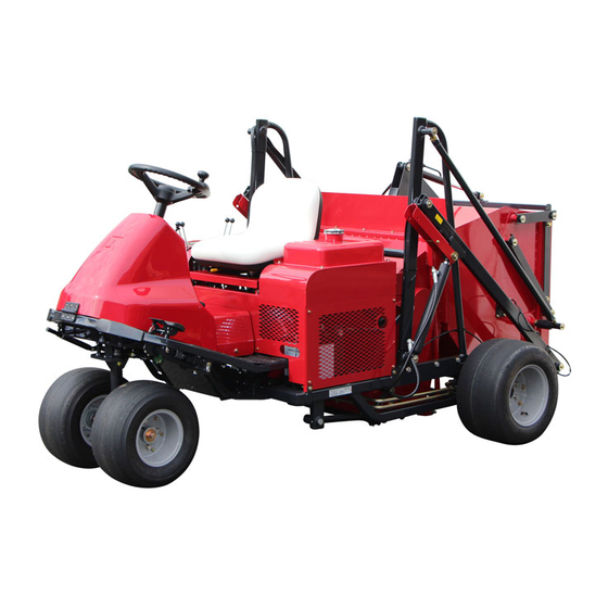
Riding sweeper
Hide thumbs
Also See for FS900:
- Owner's operating manual (113 pages) ,
- Owner's operating manual (95 pages) ,
- Owner's operating manual (69 pages)
Table of Contents
Advertisement
Quick Links
Advertisement
Chapters
Table of Contents

Related Manuals for Baroness FS900


Summary of Contents for Baroness FS900
- Page 1 Riding Sweeper Service Manual Serial No. FS900:10001- Ver.1.0...
- Page 2 The information described in this manual is subject to change for improvement without prior notice. When replacing parts, be sure to use genuine Baroness parts or parts designated by Kyoeisha. Note that the Baroness product warranty may not apply to defects caused by the use of parts from other companies.
-
Page 3: Table Of Contents
FS900 Contents Safety .............. Page 1-1 Special Tool ........... Page 7-3 Adjustment .............Page 7-4 Safe Operating Practices .......Page 1-2 Removal and installation of each section ..Page 7-11 Safety Signs and Instruction Signs ....Page 1-5 Inspection and repair of each section ..Page 7-23 Disposal ............ - Page 4 FS900 Contents...
-
Page 5: Safety
FS900 Safety Safe Operating Practices ...... Page 1-2 Training ..........Page 1-2 Preparation ..........Page 1-2 Operation ..........Page 1-3 Maintenance and storage ...... Page 1-4 Safety Signs and Instruction Signs ..Page 1-5 About Safety Signs and Instruction Signs ............Page 1-5... -
Page 6: Safe Operating Practices
FS900 Safety Failure to adequately follow these safety Incorrect hitching and load distribution precautions may cause an accident resulting in Never allow children or people unfamiliar injury or death. with these instructions to use or service the machine. Danger Danger... -
Page 7: Operation
FS900 Safety Replace all fuel tanks and container caps Do not change the engine governor settings securely. or overspeed the engine. Operating the engine at excessive speed may increase the Check that operator's presence controls, hazard of personal injury. safety switches and shields are attached and functioning properly. -
Page 8: Maintenance And Storage
FS900 Safety Take care when loading or unloading the Never allow untrained personnel to service machine into a trailer or a truck. Load or machine. unload the machine in a flat and safe place. Allow the engine/muffler to cool before Before loading or unloading, set the parking checking/maintenance. -
Page 9: Safety Signs And Instruction Signs
If they are damaged, become dirty, or peel off, replace them with new ones. Part numbers for decals that need to be replaced are listed in the parts catalog. Order them from a Baroness dealer or Kyoeisha. Safety Signs and Instruction Signs Page 1-5... - Page 10 FS900 Safety Page 1-6 Safety Signs and Instruction Signs...
-
Page 11: Disposal
FS900 Disposal Waste Disposal ........Page 2-2 About the Waste disposal ...... Page 2-2 Page 2-1... -
Page 12: Waste Disposal
FS900 Disposal Waste Disposal About the Waste disposal Make sure that waste generated when servicing or repairing the machine is disposed of in accordance with local regulations. (e.g. waste oil, antifreeze batteries, rubber products, and wires etc.) Page 2-2 Waste Disposal... -
Page 13: Maintenance Standards And Maintenance
FS900 Maintenance standards and maintenance Unit conversion ........Page 3-2 Inch–millimeter conversion table ... Page 3-2 US unit–SI unit conversion table ....Page 3-3 Maintenance standards ......Page 3-4 List of Maintenance Specifications ..Page 3-4 Tightening torques ........ Page 3-5 Standard tightening torques ....Page 3-5 Principal tightening torques .... -
Page 14: Unit Conversion
FS900 Maintenance standards and maintenance Unit conversion Inch–millimeter conversion table 1 mm = 0.03937 in 1 in = 25.4 mm Fractions Decimals Fractions Decimals 1/64 0.015625 0.397 33/64 0.515625 13.097 1/32 0.03125 0.794 17/32 0.53125 13.494 ... -
Page 15: Us Unit-Si Unit Conversion Table
FS900 Maintenance standards and maintenance US unit–SI unit conversion table To Convert Into Multiply By Miles Kilometers 1.609 Yards Meters 0.9144 Feet Meters 0.3048 Linear Measurement Feet Centimeters 30.48 Inches Meters 0.0254 Inches Centimeters 2.54 Inches Millimeters 25.4 mile Square Miles Square Kilometers 2.59... -
Page 16: Maintenance Standards
FS900 Maintenance standards and maintenance Maintenance standards List of Maintenance Specifications FS900 Engine model Vanguard 356447 No load rpm 1,400 - 3,000 rpm API Service Grade SF or higher. Engine 1.6 dm (1.6 L) (0.42 U.S. gals) SAE Viscosity that is... -
Page 17: Tightening Torques
FS900 Maintenance standards and maintenance Tightening torques Standard tightening torques Bolts and Nuts Important A number of bolts are used in each part of this machine. Be sure to re-tighten the bolts and nuts, because they may be loosened at the earlier stage of the use. - Page 18 FS900 Maintenance standards and maintenance Heat-treated bolt Strength classification 8.8 Strength classification 10.9 Nominal diameter 10.9 tib3yb-002 tib3yb-003 kgf-cm lb-in kgf-cm lb-in 5 - 7 50.99 - 71.38 44.26 - 61.96 7 - 10 71.38 - 101.97 61.96 - 88.51 8 - 11 81.58 - 112.17...
- Page 19 FS900 Maintenance standards and maintenance Hydraulic hose The tightening torques for union joints and union adaptors with parallel pipe threads (G, PF) are shown in the table below. A union joint or adaptor will not become loose or leak as long as it is tightened by the specified torque.
-
Page 20: Principal Tightening Torques
FS900 Maintenance standards and maintenance Principal tightening torques Tightening Torque by Model FS900 Tighten the following bolts and nuts to the torque specified in the table. For thread locking adhesive, apply a middle strength thread locker (ThreeBond 1322 anaerobic adhesives). -
Page 21: General Precautions
FS900 Maintenance standards and maintenance General precautions Housing Bearing Bearing Bearing driver The bearing is a precision machine part. When pressing the bearing into the shaft and Install the bearing in an appropriate work housing evenly, apply pressure evenly with... -
Page 22: Stop Ring
FS900 Maintenance standards and maintenance When attaching the stop ring for a shaft, Stop ring assemble the stop ring so that the sharp edge side receives the load (indicated by an Caution arrow). When attaching the stop ring to a hole or a... -
Page 23: Jacking Up The Machine
FS900 Maintenance standards and maintenance Jacking up the machine Right front brush frame mount area Right rear frame area About the Jacking up the machine Left front brush frame mount area Left rear frame area Warning Right front brush frame mount area... - Page 24 FS900 Maintenance standards and maintenance Left rear frame area rwyt62-030 Jack-up Points_005 Page 3-12 Jacking up the machine...
-
Page 25: Greasing
FS900 Maintenance standards and maintenance Greasing No. of Location Greasing About Greasing Points Traveling pedal fulcrum Since there may be adhesion or damage due Brush frame fulcrum to lack of grease on moving parts, they must be greased. Flange bearing Add urea-based No. - Page 26 FS900 Maintenance standards and maintenance Flange bearing Belt tension lever fulcrum (lower pulley for pump) 8bq62b-081 8bq62b-084 Greasing Points_004 Upper connecting pipe Greasing Points_007 There is one point each on the left and Brake pedal fulcrum right. 8bq62b-085 8bq62b-082 Greasing Points_008...
- Page 27 FS900 Maintenance standards and maintenance Bucket lid cylinder Rear roller There is one point each on the left and right. 8bq62b-087 Greasing Points_010 8bq62b-090 Lower adjusting pipe There is one point each on the left and Greasing Points_013 right. Front wheel arm...
- Page 28 FS900 Maintenance standards and maintenance Page 3-16 Greasing...
-
Page 29: Hydraulic System
FS900 Hydraulic system Maintenance ........... Page 4-2 Maintenance .......... Page 4-2 Specifications ........Page 4-3 Specifications list ........Page 4-3 Hydraulic System Layout ....... Page 4-4 Flow of Hydraulic Oil ......Page 4-6 General instructions ......Page 4-9 Hydraulic hose ........Page 4-9 Hydraulic fitting ........ -
Page 30: Maintenance
For information on daily checks, maintenance and handling of the machine, please refer to the separate FS900 Owner's Operating Manual and Parts Catalog. To maintain the integrity of the hydraulic device, you must not overhaul the device for maintenance. -
Page 31: Specifications
FS900 Hydraulic system Specifications Specifications list PSV-16AHG-2 made by KYB Displacement 0 - 16.4 cm /rev (0 - 1.00 in /rev) Piston pump High-pressure relief set 20.6 MPa (210.6 kgf/cm ) (2,987 psi) pressure Displacement 4.9 cm /rev (0.3 in... -
Page 32: Hydraulic System Layout
FS900 Hydraulic system Hydraulic System Layout dwb7jb-011 Hydraulic System Layout_001 Piston pump Orbit motor Stack valve Up/down cylinder FPV1 series valve Suction filter Wheel motor Line filter Page 4-4 Specifications... - Page 33 FS900 Hydraulic system Piston pump Suction filter This converts the mechanical energy of the This is located between the tank and the engine to fluid energy by using the pump so as to ensure that impurities do not reciprocating motion of the piston.
-
Page 34: Flow Of Hydraulic Oil
FS900 Hydraulic system Flow of Hydraulic Oil Flow of Oil during Forward Traveling zy6f9z-006 Flow of Oil during Forward Traveling_001 shows flow of oil. The flow of oil shows that for forward traveling. shows port name. Piston pump Wheel motor (left) - Page 35 FS900 Hydraulic system Flow of Oil During Brush Frame Lowering, Rolling, and Brush Rotation vuu73b-001 Flow of Oil During Brush Frame Lowering, Rolling, and Brush Rotation_001 shows the flow of oil. This oil flow occurs when the brush frame is lowered, rolling is performed, and the brush is rotated.
- Page 36 FS900 Hydraulic system Oil Flow When Raising Bucket and Opening Bucket Lid 511omk-001 Oil Flow When Raising Bucket and Opening Bucket Lid_001 shows the flow of oil. This oil flow occurs when the bucket is raised and the bucket lid is opened.
-
Page 37: General Instructions
FS900 Hydraulic system Hydraulic fitting General instructions Bite type tube fitting Hydraulic hose Preliminary tightening (Preset) Hydraulic hoses are subjected to excessive load when weathered, exposed to the sun or Cut the tube at the designated length at a chemicals, stored in a very hot storage right angle. - Page 38 FS900 Hydraulic system Matchmark the zero point and further tightening of 3/4 to one turn will cause the sleeve to bite into the tube. w7s31b-004 Bite type tube fitting_004 Fix the temporary tightening tool onto the w7s31b-007 vise and apply hydraulic oil to the threads, tapered part, and sleeve.
- Page 39 FS900 Hydraulic system Final tightening (Reset) Fit the preliminary tightened tube onto the fitting body. Tighten with a spanner to the point where some resistance is suddenly felt, then further tighten with the nut for a 1/4 turn. w7s31b-009 Bite type tube fitting_009...
- Page 40 FS900 Hydraulic system Make sure that the positions of the nut, Fitting with parallel pipe threads (O-ring sealing washer, and O-ring are correct. system) If they are in the correct positions, the washer is pressed into the upper end of the groove of the main body.
- Page 41 FS900 Hydraulic system O-ring Sheet surface Caution Never give the locknut more than one turns. If you give it more than one turn, the thread fit between the other side port and locknut becomes loose, which reduces the thread strength.
- Page 42 FS900 Hydraulic system Before connecting the joint, wind sealing Taper Pipe (PT) Thread Joint (Sealing Tape tape on the taper thread portion. (See "How Method) to Use the Sealing Tape" (Page 4-14) .) Make sure that the taper thread portion is not damaged or contaminated with foreign objects.
- Page 43 FS900 Hydraulic system Wrap it in clockwise direction (direction to ・ tighten the screw). Wrapping in the opposite direction may cause the tape to be easily peeled off. ugh2b1-002 How to Use the Sealing Tape_002 Sealing area Sealing tape Clockwise direction Wrap it in clockwise direction (direction to tighten the screw) about 1.5 to 2 turns...
-
Page 44: Towing
FS900 Hydraulic system Since this contaminant causes damage to Towing other hydraulic equipment, such debris and contaminant must be removed to prevent Important further failure of other hydraulic equipment. In the event that failure of hydraulic equipment Going over the limit of towing may lead to the is found in the hydraulic circuit, remove failure of hydraulic equipment. -
Page 45: Hydraulic Circuit Flow
FS900 Hydraulic system Hydraulic circuit flow Traveling circuit Forward traveling To Valve, Multiple FRV1 Wheel motor 10 m Piston pump R1 Relief pressure 20.6MPa R2 Relief pressure 1.0MPa Suction filter Wheel motor High pressure Low pressure - charge Intake - return... - Page 46 FS900 Hydraulic system Backward traveling To Valve, Multiple FRV1 Wheel motor 10 m Piston pump R1 Relief pressure 20.6MPa R2 Relief pressure 1.0MPa Suction filter Wheel motor High pressure Low pressure - charge Intake - return Direction 7edlvx-029E Backward traveling_001...
-
Page 47: Work Machine Circuit
FS900 Hydraulic system Work machine circuit Raising the Brush Frame Brush frame up/down Lid open/close Bucket up/down Brush rotation motor (+Surface compaction) Stack valve R4 Relief valve 13.7MPa High pressure Low pressure - charge Intake - return Direction 5fl96a-001E Raising the Brush Frame_001... - Page 48 FS900 Hydraulic system Lowering the Brush Frame and Rotating the Brush Brush frame up/down Lid open/close Bucket up/down Brush rotation motor (+Surface compaction) Stack valve R4 Relief valve 13.7MPa High pressure Low pressure - charge Intake - return Direction 22c3vd-001E...
- Page 49 FS900 Hydraulic system Lowering the Brush Frame and Rotating the Brush (with Roller pressure) Brush frame up/down Lid open/close Bucket up/down Brush rotation motor Valve, Multiple FRV1 (+Surface compaction) Relief valveR3 0.9MPa Stack valve R4 Relief valve 13.7MPa High pressure...
- Page 50 FS900 Hydraulic system Raising the Bucket and Opening the Bucket Lid Brush frame up/down Lid open/close Bucket up/down Brush rotation motor (+Surface compaction) Stack valve R4 Relief valve 13.7MPa High pressure Low pressure - charge Intake - return Direction 5bjwpw-001E...
- Page 51 FS900 Hydraulic system Lowering the Bucket and Closing the Bucket Lid Brush frame up/down Lid open/close Bucket up/down Brush rotation motor (+Surface compaction) Stack valve R4 Relief valve 13.7MPa High pressure Low pressure - charge Intake - return Direction 7cu6iu-001E...
-
Page 52: Special Tool
FS900 Hydraulic system Special Tool List of Special Tools Pressure gauge for high pressure measurements Pressure: For the range of 0 - 35 MPa For the range of 0 - 5,076.40 psi K4701000010 For the range of 0 - 356.90 kgf/cm Primarily used for measuring the pressure of high-pressure parts. - Page 53 FS900 Hydraulic system Pressure gauge seal Inserted between the pressure gauge K4701000050 and the pressure gauge joint. vasdfi-005 Gauge valve Used to temporarily shut off the fluid to be measured during maintenance, K4701000060 inspection, or repair etc. of the pressure gauge.
- Page 54 FS900 Hydraulic system Joint, cast iron PT3/8 PF3/8 Used to insert the pressure gauge K3024000042-Y between the hydraulic hoses. vasdfi-013 Special adapter PF1/4 PT3/8 Used as an adapter for the T-joint K3009000042-Y during pressure measurements. vasdfi-015 Adapter 1013-9 Used as an adapter for the T-joint...
- Page 55 FS900 Hydraulic system WP70-9 hose-650 Used as a hydraulic hose for K3101310650 extremely low pressure measurements. vasdfi-008 Adapter 1013-6 Used as a connector when installing K3000060002-Y the pressure gauge to the pressure measuring port. q9c6v6-047 Special Tool Page 4-27...
-
Page 56: Measurement
FS900 Hydraulic system Review the measuring method before Measurement starting measurement. Note Before measurement, check for poor adjustment, clogging or breakage. The most effective way of solving problems in Warm up the hydraulic oil before starting the hydraulic system is to use a measuring pressure measurement. -
Page 57: Traveling Circuit
FS900 Hydraulic system Traveling circuit Forward To Valve, Multiple FRV1 Wheel motor Cartridge filter 10 m Pressure gauge Piston pump R1 Relief pressure 20.6MPa R2 Relief pressure 1.0MPa Suction filter Wheel motor High pressure Low pressure - charge Intake - return... - Page 58 FS900 Hydraulic system Secure the pressure gauge for high Caution pressure measurements with a band or the like. Before starting pressure measurement, make sure that there are no people around the machine. Caution For the pressure gauge and hydraulic hose, use devices capable of withstanding at least 30 MPa (306.43 kgf/cm...
- Page 59 FS900 Hydraulic system Caution When resistance is applied to the main body frame area, lower the bucket to a position where the bottom section of the bucket does not come in contact with the sling, and then measure the pressure.
- Page 60 FS900 Hydraulic system Reverse To Valve, Multiple FRV1 Wheel motor Cartridge filter 10 m Piston pump R1 Relief pressure 20.6MPa R2 Relief pressure 1.0MPa Suction filter Pressure gauge Wheel motor High pressure Low pressure - charge Intake - return Direction...
- Page 61 FS900 Hydraulic system Secure the pressure gauge for high Caution pressure measurements with a band or the Before starting pressure measurement, make like. sure that there are no people around the machine. Caution For the pressure gauge and hydraulic hose, use devices capable of withstanding at least 30 MPa (306.43 kgf/cm...
- Page 62 FS900 Hydraulic system Up/Down circuit Brush frame up/down Lid open/close Bucket up/down Brush rotation motor (+Surface compaction) Pressure gauge Stack valve R4 Relief valve 13.7MPa High pressure Low pressure - charge Intake - return Direction z4kw7w-038E Up/Down Circuit_001 Page 4-34...
- Page 63 FS900 Hydraulic system Caution Important Before starting pressure measurement, make The G port plug is a PT screw. sure that there are no people around the When installing the plug, wrap the thread area machine. with seal tape, and tighten the plug using the appropriate torque.
- Page 64 FS900 Hydraulic system Surface Compaction Circuit Brush frame up/down Lid open/close Bucket up/down Brush rotation motor Valve, Multiple FRV1 (+Surface compaction) Relief valveR3 0.9MPa Pressure gauge Stack valve R4 Relief valve 13.7MPa High pressure Low pressure - charge Intake - return...
- Page 65 FS900 Hydraulic system Secure the pressure gauge for extremely Caution low pressure measurements to the main Before starting pressure measurement, make frame using bands. Note: sure that there are no people around the Route the hydraulic hose in positions that machine.
- Page 66 FS900 Hydraulic system Charge Circuit To Valve, Multiple FRV1 Wheel motor Cartridge filter 10 m Pressure gauge Piston pump R1 Relief pressure 20.6MPa R2 Relief pressure 1.0MPa Suction filter Wheel motor High pressure Low pressure - charge Intake - return...
- Page 67 FS900 Hydraulic system Install the pressure gauge for extremely low Caution pressure measurements between the Before starting pressure measurement, make removed hydraulic hose and cartridge filter elbow. sure that there are no people around the machine. Secure the pressure gauge for extremely low pressure measurements with bands.
-
Page 68: General Inspection And Repair
See the list in "Tightening torques" (Page 3-5) . Note that the Baroness product warranty may not apply to defects caused by incorrect or overtorque tightening etc. Check the amount of oil in the hydraulic tank. -
Page 69: Hydraulic Hose, Piping
FS900 Hydraulic system Drain the oil from the hydraulic hoses and Hydraulic hose, piping piping while the oil is still warm. Check the hydraulic tank and suction filter, Warning and clean. When checking for pinhole leakage of the Fit the hydraulic hoses, piping and hydraulic hydraulic circuit or oil leakage of the nozzle, fittings that have been removed. -
Page 70: Air Bleeding
FS900 Hydraulic system After the hydraulic circuit is filled with oil, Air bleeding operate the up/down lever and switches to operate the up/down cylinder several times. Caution Stop the engine immediately when the cylinder does not move within 10 to 15... -
Page 71: Inspection And Repair Of Each Section
FS900 Hydraulic system Remove the bolts, and then open the cover. Inspection and repair of each section Hydraulic Oil Inspection of Hydraulic Oil On a level surface, raise the brush frame and maintain that position. Make sure that the oil level is at the middle of the oil gauge. - Page 72 FS900 Hydraulic system Open the tank cap, and then pour new oil Change of Hydraulic Oil from the fill port until the oil level reaches the middle of the oil gauge on the hydraulic Warning tank. The hydraulic tank capacity is...
-
Page 73: Hydraulic Oil Filter
FS900 Hydraulic system Hydraulic oil filter Replacing the Hydraulic Oil Suction Filter Replacing the Hydraulic Oil Line Filter Important Before replacing the hydraulic oil suction filter, Important be sure to drain the hydraulic oil into a Before replacing the hydraulic oil line filter, be container. - Page 74 FS900 Hydraulic system Page 4-46 Inspection and repair of each section...
-
Page 75: Electrical System
FS900 Electrical system Maintenance ........... Page 5-2 About Maintenance ........Page 5-2 Specifications ........Page 5-3 Electrical Part Layout ......Page 5-3 Special Tool ..........Page 5-4 Special tools list ........Page 5-4 Measurement ..........Page 5-5 Battery ........... Page 5-5 Interlock System ........Page 5-6 Adjustment .......... -
Page 76: Maintenance
FS900 electrical system. For information on daily checks, maintenance and handling of the machine, please refer to the separate FS900 Owner's Operating Manual and Parts Catalog. For details on handling the battery, please refer to the separate Battery Instruction Manual. -
Page 77: Specifications
FS900 Electrical system Specifications Electrical Part Layout BUCKET BUZZER erq4ky-011 Electrical Part Layout_001 Brake pedal switch Key switch Seat switch [NC type (push to turn off)] Power relay CA1-DC12V-N Warning buzzer switch Sensor Power relay MR5A602A1K Hour meter Magnetic switch... -
Page 78: Special Tool
FS900 Electrical system Brake pedal switch A plastic magnet for detection is attached to The brake pedal switch is one of the safety the traveling pedal arm section. This switches that constitute the interlock system. traveling pedal proximity switch detects that It is located on the brake fulcrum. -
Page 79: Measurement
FS900 Electrical system Measurement of specific weight of 12V Measurement battery Battery Check all the cells after charge. Replace the battery when the specific Measurement of Battery Specific Weight weight is 1.225 or less, or gap of that between each cell is 0.05 or more. - Page 80 FS900 Electrical system Interlock System The interlock system is a safety system to prevent injury or accident caused by operator inattentiveness using combined control with multiple switches and sensors. The engine stop switch is activated by the seat switch, traveling pedal neutral switch, and brake pedal switch, and is linked with the fuel stop switch.
-
Page 81: Adjustment
FS900 Electrical system Forward/reverse pedal proximity switch Adjustment Adjust the position of the forward/reverse pedal Brake pedal switch proximity switch so that gap A is 5 mm (0.20 in) Adjust the brake pedal switch by loosening the or less when the forward and reverse pedals nuts so that A is 2 mm (0.079 in) or more when... -
Page 82: Electrical Components
FS900 Electrical system Electrical components About the Electrical components Warning When servicing electrical components, be sure to disconnect the negative battery cable. Safety Switches The following devices are used as safety switches to prevent injuries and accidents due to operator inattentiveness. - Page 83 FS900 Electrical system Interlock System Circuit Vout Vout 14.BW 26.YR 20.Y 19.BW 26.YR 30.YR WR 1 START 3.RL RL 3 4.BW BW 4 5.BY BY 5 22.B 7.YR 32.Br 36.BW NC FREE PUSH 1j8hum-001 Interlock System Circuit_001 Key switch Seat switch...
-
Page 84: Traveling Pedal Proximity Switch
FS900 Electrical system The following describes the state of the Traveling Pedal Proximity Switch interlock system circuit. The traveling pedal proximity switch is an NC The key switch is in the START position ・ switch that detects that the distance away from (starter motor start position). -
Page 85: Forward/Reverse Pedal Proximity Switch Nc
FS900 Electrical system Forward/reverse pedal proximity switch NC Connector terminal (+) Connector terminal Vout (+) Inspection of Control Output Connector terminal (-) Caution Do not short-circuit the battery terminals. Follow the steps below to connect the battery and a tester to the connector terminal of the forward/reverse pedal proximity switch NC. -
Page 86: Seat Switch
FS900 Electrical system Seat Switch Inspection of Output Voltage The seat switch is located right underneath the Caution seat and is usually conducted. It is normal if its condition is stopped when seated. Do not short-circuit the battery terminals. Follow the steps below to connect the... -
Page 87: Buzzer Switch
FS900 Electrical system Buzzer Switch Power Relay The buzzer switch is located on the operation Power Relay 602 panel. Interlock System Power Relay ■ Disconnect the bullet connectors. The power relay [MR5A602A1K] (gray) is one part that makes up the interlock system,... - Page 88 FS900 Electrical system Normal operation is when there is continuity between relay terminals 3 and 6 and no continuity between relay terminals 4 and 5. 38jyg3-005 Inspection of Power Relay_002 Caution Do not short-circuit the battery terminals. Normal operation is when there is no...
-
Page 89: Key Switch
FS900 Electrical system Power Relay CA1aF Caution Do not short-circuit the battery terminals. Interlock System Power Relay ■ The power relay [CA1aF-12V-N-5] is one Normal operation is when there is no part that makes up the interlock system, and conduction between between relay... -
Page 90: Hour Meter
FS900 Electrical system Fuses are located in the lower right corner Hour meter behind the front cover and consist of the main harness fuse for the entire circuit. The hour meter is located in the operation It is glass fuse 20 A (φ6.4 x 30 mm). -
Page 91: Magnetic Switch
FS900 Electrical system Magnetic switch The magnetic switch is located on the right side behind the rear cover. When the key switch is set to the “START” position, the coil in the magnetic switch magnetically attracts the plunger. When the plunger comes into close... -
Page 92: General Inspection And Repair
FS900 Electrical system General inspection and repair Danger Danger Do not allow anyone to handle the battery who Battery does not fully understand the correct battery Handling of the battery handling procedures and relevant dangers. When handling the battery, wear protective For details on handling the battery, please glasses and rubber gloves, etc. - Page 93 FS900 Electrical system Danger Danger Caution Do not allow anyone to handle the battery who If the electrolyte overflows from the battery, does not fully understand the correct battery wipe it with a wet cloth. handling procedures and relevant dangers.
- Page 94 FS900 Electrical system If it is not, tighten the nuts securing the Upper limit battery until it is firmly secured. Lower limit If the battery is not firmly secured by the mounting bracket, the battery could move Replacement of Battery...
- Page 95 FS900 Electrical system Caution (-) Cable (+) Cable Select a battery that has the same terminal positions (the positions of the positive and Installing a new battery negative terminals) as the old one. Install the new battery with the correct...
- Page 96 FS900 Electrical system Battery Charge Warning Charging the battery mounted on the vehicle When charging the battery with the battery may cause ignition, explosion, or damage on charger, follow the correct steps according to the vehicle or equipment. the handling instructions attached to the If there is no way other than to charge the battery charger.
- Page 97 FS900 Electrical system Important Fast charging is not suitable for charging to recover the battery left for a long time. A high electrolyte temperature deteriorates parts such as polar plates inside the battery and shorten its lifetime. General inspection and repair...
- Page 98 FS900 Electrical system Page 5-24 General inspection and repair...
-
Page 99: Main Body
FS900 Main body Maintenance ........... Page 6-2 About Maintenance ........Page 6-2 Specifications ........Page 6-2 Tire pressure ..........Page 6-2 Adjusted Value ........Page 6-2 Special Tool ..........Page 6-3 List of Special Tools .......Page 6-3 Adjustment ..........Page 6-5 Brake ............. Page 6-5 Neutral Position of the Piston Pump .. -
Page 100: Maintenance
This chapter provides descriptions of the main inspection and maintenance procedures for the FS900. For information on daily checks, maintenance and handling of the machine, please refer to the separate FS900 Owner's Operating Manual and Parts Catalog. Specifications Tire pressure ... -
Page 101: Special Tool
FS900 Main body Special Tool List of Special Tools 6207 Bearing driver Used when installing bearings with K4802000492 outer Φ72 and inner Φ35 q9c6v6-009 6206 Bearing driver Used when installing bearings with K4802000832 outer Φ62 and inner Φ30 q9c6v6-009 6205 Bearing driver... - Page 102 FS900 Main body 6305 Bearing driver Used when installing bearings with K4802000832 outer Φ62 and inner Φ25 q9c6v6-010 Page 6-4 Special Tool...
-
Page 103: Adjustment
FS900 Main body Adjustment Danger Danger It would be extremely dangerous and may Brake result in an unexpected accident if the left and Adjustment of Brake right brakes are not equally effective. If the left and right brakes are not equally... - Page 104 FS900 Main body Adjustment of Parking Brake Danger Danger Make sure that the brake wire is not cracked or damaged. Danger Danger Make sure that the brake is effective on slopes and that it is not applied any longer ulabms-008 when you release it.
-
Page 105: Neutral Position Of The Piston Pump
FS900 Main body Neutral Position of the Piston Pump Piston pump Adjusting the Neutral Position of the Piston Pump Camshaft If the machine moves forward or backward Loosen the adjuster nuts. while the traveling pedals are released, they are not set to the neutral position. -
Page 106: Pump Drive Belt
FS900 Main body Insert the push-pull cable, and then install the washer and cotter pin. hsn2jo-003 Adjusting the Neutral Position of the Piston Pump_005 Push-pull cable Cotter pin Washer Pump Drive Belt Adjustment of Pump Drive Belt Press the middle of the belt with your finger to check the belt tension. -
Page 107: Steering
FS900 Main body When the steering wheel stopper does not Steering come into contact with the steering wheel stopper bolt, adjust the tie rod so that it Adjusting the Steering Angle of the Steering Wheel does. Secure the steering stopper bolt in the location 17 mm (0.669 in) backward from... -
Page 108: Removal And Installation Of Each Section
FS900 Main body Loosen the tilt lever. Removal and installation of each Loosen the nuts and the bolts with a section hexagonal hole. Steering Section Loosen the bolt, and remove the tilt lever, disc spring washer, and washer. Removing the Steering Wheel Section Move the machine to level surface. - Page 109 Main body Installing the Steering Wheel Section Caution Refer to the Tightening Torque Table. Note that the Baroness product warranty may not apply to defects caused by incorrect or overtorque tightening, etc. Important Be sure to replace the U nut with a new one.
-
Page 110: Front Wheels Section
Installing the Front Wheel Section Caution Refer to the Tightening Torque Table. 6717fe-001 Note that the Baroness product warranty may Removing the Front Wheel Section_001 not apply to defects caused by incorrect or Wheel installation shaft ass'y overtorque tightening, etc. -
Page 111: Inspection And Repair Of Each Section
FS900 Main body Tap the metal pipe with a hammer in the Inspection and repair of each section direction of the arrow, and remove the bearing. Axle Mounting Bracket Important Inspecting the Axle Installation Bracket Be sure to replace the bearing with a new Wear of bearings due to frequent usage and one. -
Page 112: Front Wheel Arm
FS900 Main body Front Wheel Arm Inspecting the Front Wheel Arm Wear of the bearing and thrust bearing due to frequent usage and damage to bearings etc. caused by moisture entry may prevent smooth rotation of the ball. Inspect the bearing, thrust bearing, front wheel arm, and the like, and replace the parts as necessary. - Page 113 FS900 Main body Temporarily install the tie rod end right Caution ass'y. Note that the Baroness product warranty may not apply to defects caused by incorrect or overtorque tightening, etc. Important Be sure to replace the bearing and thrust bearing with new ones.
- Page 114 FS900 Main body Install the bearing cover, and secure it with heat-treated bolt and spring washer. 6717fe-002 Inspecting the Front Wheel Arm_006 Front wheel arm ass'y Jack Heat-treated bolt Spring washer Bearing cover Bearing Tie rod end right ass'y Housing (main body) Apply grease to the grease points.
-
Page 115: Wheel Mounting Shaft
Caution Remove the wheel tightening washer and Refer to the Tightening Torque Table. washer A. Note that the Baroness product warranty may Remove the front wheel housing ass'y. not apply to defects caused by incorrect or Remove washer B. overtorque tightening, etc. -
Page 116: Brake
FS900 Main body Remove the springs on both sides. Brake Note: They are different in size. A worn brake shoe will increase the amount of brake pedal depression, and may cause the pedal to touch the floor or result in uneven braking. - Page 117 FS900 Main body Remove the shoe and the adjuster screw. Do not insert the key to the motor shaft and tentatively assemble the drum. z2sgi8-006 z2sgi8-004 Disassembly and assembly of brake_006 Disassembly and assembly of brake_004 Adjuster screw Shoe Shoe...
- Page 118 FS900 Main body Page 6-20 Inspection and repair of each section...
-
Page 119: Operating Machine And Mower Units
FS900 Operating Machine and Mower Units Maintenance ........... Page 7-2 About Maintenance ........Page 7-2 Specifications ........Page 7-2 Grease ........... Page 7-2 Adjusted Value ........Page 7-2 Special Tool ..........Page 7-3 List of Special Tools .......Page 7-3 Adjustment ..........Page 7-4 Adjustment of Belt Tension ....Page 7-4... -
Page 120: Maintenance
FS900 work machine. For information on daily checks, maintenance and handling of the machine, please refer to the separate FS900 Owner's Operating Manual and Parts Catalog. For information on attaching and removing optional parts and attachments, refer to the handling instructions for the corresponding attachment. -
Page 121: Special Tool
FS900 Operating Machine and Mower Units Special Tool List of Special Tools 6006 Bearing driver Used when installing bearings with K4802000922 outer Φ55 and inner Φ30 q9c6v6-010 6005 Bearing driver Used when installing bearings with K4802000502 outer Φ47 and inner Φ25... -
Page 122: Adjustment
FS900 Operating Machine and Mower Units Loosen the bolt, and then tighten the nut to Adjustment adjust the tension pulley. Adjustment of Belt Tension Caution Be sure to stop the engine before adjusting the belts. Important Make sure that the belt has the specified amount of tension. -
Page 123: Adjustment Of Brushes
FS900 Operating Machine and Mower Units Remove the cotter pin and round head pin, Adjustment of Brushes and then lower the cylinder lock. Important If the brush operation height is inadequate, cores will not be properly collected. Important If the left and right sides of the brushes are at different heights, pickup will be irregular, and the brushes will wear unevenly. - Page 124 Caution Refer to "Tightening torques" (Page 3-5) . xsi3tb-004 Note that the Baroness product warranty may Adjustment of Brushes_005 not apply to defects caused by incorrect or overtorque tightening etc. Brush cover Loosen the bolts securing the brush.
-
Page 125: Adjustment Of Rotary Plates
FS900 Operating Machine and Mower Units Insert the round head pin through the holes Adjustment of Rotary Plates in the cylinder lock, and then install the cotter pin. Important Adjust all rotary plates properly. Otherwise vibration may occur, causing damage or an accident. -
Page 126: Adjusting The Bucket
Loosen the bolts securing the rotary plate. Caution Refer to "Tightening torques" (Page 3-5) . Note that the Baroness product warranty may not apply to defects caused by incorrect or overtorque tightening etc. Slowly rotate the rotary plates by hand, check the clearance again and tighten the bolts. - Page 127 10 mm (0.393 in) setting value. Caution Refer to the Tightening Torque Table. Note that the Baroness product warranty may not apply to defects caused by incorrect or overtorque tightening, etc. Tighten the installation bolts. Adjustment...
-
Page 128: Adjusting The Bucket Lid
Adjust the cylinder adjustment area so that Refer to the Tightening Torque Table. the distance indicated by the arrow is 20 mm Note that the Baroness product warranty may (0.787 in). not apply to defects caused by incorrect or overtorque tightening, etc. -
Page 129: Removal And Installation Of Each Section
FS900 Operating Machine and Mower Units Remove the bucket lid open/close kit from Removal and installation of each the machine, and place the kit as shown in section the figure. Bucket Removing the Bucket Move the machine to level ground, then apply the parking brake. - Page 130 FS900 Operating Machine and Mower Units Remove the sensor wire from the bucket Bucket up/down cylinder arm. Split pin Washer Bolt Spring washer Washer Caution The bucket is heavy. Be sure to use a hoist or a chain block. yi8si6-005...
- Page 131 The bucket is heavy. Be sure to use a hoist or a chain block. Caution Refer to the Tightening Torque Table. Note that the Baroness product warranty may not apply to defects caused by incorrect or overtorque tightening, etc. Important When installing the bucket arm and adjusting pipe, apply grease to moving parts.
-
Page 132: Bucket Mounting Frame
Caution 4a6cw2-002 Removing the Bucket Mounting Frame_002 Refer to the Tightening Torque Table. Sling Note that the Baroness product warranty may not apply to defects caused by incorrect or Bucket mounting frame overtorque tightening, etc. For installation, reverse the removing procedure. -
Page 133: Working Unit
FS900 Operating Machine and Mower Units Working Unit Operating section Sling Removing the Operating Section Remove the split pin, flathead pin, and Remove the bucket. (See "Removing the washer. Bucket" (Page 7-11) .) Remove the up/down cylinder from the Remove the bucket mounting frame. (See operating section, and secure it to the "Removing the Bucket Mounting Frame"... - Page 134 Refer to the Tightening Torque Table. Follow the same steps to remove it from the Note that the Baroness product warranty may other side. not apply to defects caused by incorrect or overtorque tightening, etc.
-
Page 135: Brush Shaft
FS900 Operating Machine and Mower Units Remove the bolt, spring washer, washer, Brush Shaft and double-head round key, and remove the pulley. Removing the Brush Shaft Move the machine to level ground, then apply the parking brake. Raise the bucket to its highest position. - Page 136 Washer Spring washer Installing the Brush Shaft Caution Refer to the Tightening Torque Table. Note that the Baroness product warranty may not apply to defects caused by incorrect or overtorque tightening, etc. Important The brush shaft has a specific installation direction.
-
Page 137: Rotary Shaft
FS900 Operating Machine and Mower Units Remove the bolt, spring washer, washer, Rotary Shaft and double-head round key, and remove the rotary pulley. Removing the Rotary Shaft Move the machine to level ground, then apply the parking brake. Raise the bucket to its highest position. - Page 138 FS900 Operating Machine and Mower Units Remove the flange unit. Remove the two bolts, spring washers, and washers from the motor housing, and then remove the rotary shaft. 2,3,4 it27ka-003 Removing the Rotary Shaft_005 it27ka-004 Flange unit Removing the Rotary Shaft_006...
- Page 139 Operating Machine and Mower Units Installing the Rotary Shaft Caution Refer to the Tightening Torque Table. Note that the Baroness product warranty may not apply to defects caused by incorrect or overtorque tightening, etc. Important When installing the rotary shaft, apply grease to the input area.
-
Page 140: Rear Roller Assy
See the list in Tightening torques. Slide the roller bracket in the direction of Note that the Baroness product warranty may the arrow, and remove the roller bracket not apply to defects caused by incorrect or from the boss. -
Page 141: Inspection And Repair Of Each Section
FS900 Operating Machine and Mower Units Inspection and repair of each section Important To keep the position of raised bucket, be sure Brush to lock it with the cylinder lock. Change of Brushes Remove the cotter pin and round head pin, and then lower the cylinder lock. - Page 142 Caution xsi3tb-004 Refer to "Tightening torques" (Page 3-5) . Change of Brushes_005 Note that the Baroness product warranty may not apply to defects caused by incorrect or Brush cover overtorque tightening etc. Remove the bolts securing the brush.
-
Page 143: Rotary Plate
FS900 Operating Machine and Mower Units Rotary Plate Important To keep the position of raised bucket, be sure Change of Rotary Plates to lock it with the cylinder lock. Caution Remove the cotter pin and round head pin, If the rotary plate operation height is and then lower the cylinder lock. - Page 144 Brush cover Caution Remove the bolts securing the rotary plate. Refer to "Tightening torques" (Page 3-5) . Note that the Baroness product warranty may not apply to defects caused by incorrect or overtorque tightening etc. Important Do not forget to tighten bolts properly.
-
Page 145: Roller
FS900 Operating Machine and Mower Units Remove the left and right stop rings. Roller Inspecting the Rear Roller Wear of bearings due to frequent usage and damage to bearings etc. caused by moisture entry may prevent smooth rotation of the rear roller. - Page 146 FS900 Operating Machine and Mower Units Remove the oil seal, collar, and taper Remove the oil seal from the seal housing. bearing (inner). y2frzp-002 Inspection of Rear Roller_004 Roller shaft Stop collar Stop ring Drum collar stopper Oil seal Collar...
- Page 147 Taper roller bearing Oil seal Caution Refer to the Tightening Torque Table. Note that the Baroness product warranty may not apply to defects caused by incorrect or overtorque tightening, etc. Install the rear roller ass'y following the reversed procedure of the procedure 2 to...
-
Page 148: Motor Housing
FS900 Operating Machine and Mower Units Apply a profuse amount of grease to the lip Motor Housing of the oil seal. Inspecting the Motor Housing Wear of bearings due to frequent usage and damage to bearings etc. caused by moisture entry may prevent smooth rotation of the shaft. -
Page 149: Troubleshooting
FS900 Troubleshooting Relating to the Engine ......Page 8-2 Relating to Traveling ......Page 8-4 Relating to Steering .......Page 8-5 Operating Machine Related ....Page 8-6 Page 8-1... -
Page 150: Relating To The Engine
FS900 Troubleshooting Relating to the Engine Problem Cause Reference Operation of interlock system Electrical System - Measurements - Interlock (Operator is not sitting on seat, brake is not System pressed, traveling pedal is not in neutral) Interlock system component failure... - Page 151 FS900 Troubleshooting Problem Cause Reference Operation of interlock system Electrical System - Measurements - Interlock (The operator leaves the seat without applying the System parking brake.) Interlock system component failure Electrical System - Electrical (Seat switch, brake pedal switch, traveling pedal...
-
Page 152: Relating To Traveling
FS900 Troubleshooting Relating to Traveling Problem Cause Reference Hydraulic System - General Amount of hydraulic oil is low. Inspection, Repair - Hydraulic Main Body - Adjustment - Loose pump V bolt Pump Drive Belt This machine's Owner's Unload valve is pressed. -
Page 153: Relating To Steering
FS900 Troubleshooting Relating to Steering Problem Cause Reference Main Body - Inspection of Each Part, Malfunction of front wheel arm Repair - Front Wheel Arm - Inspecting the fulcrum bearing Front Wheel Arm Main Body - Inspection of Each Part,... -
Page 154: Operating Machine Related
FS900 Troubleshooting Operating Machine Related Problem Cause Reference Malfunction of stack valve Repair or replace the stack valve. Malfunction of gear pump Repair or replace the gear pump. Hydraulic System - Inspection of Operating machine does not Blocked suction filter... -
Page 155: Reference
FS900 Reference Specifications ........Page 9-2 Maintenance Schedule ......Page 9-3 Hydraulic Circuit Diagram .....Page 9-5 Electrical Circuit ........Page 9-6 Electric Wiring Diagram ......Page 9-7 List of Consumables ......Page 9-8 Page 9-1... -
Page 156: Specifications
FS900 Reference Specifications Total length 256 cm (100.79 in) Total width 177 cm (69.69 in) Total height 149 cm (58.66 in) Maximum raised bucket height 150 cm (62.20 in) Main body Weight (empty fuel tank) 757 kg (1668.87 lb) Drive Forward 0 - 17.0 km/h (0 - 10.57 mph) -
Page 157: Maintenance Schedule
FS900 Reference Maintenance Schedule FS900 Follow the maintenance schedule below. ○・・・Inspect, adjust, supply, clean ●・・・Replace (first time) △・・・Replace Maintenance item Tightening the parts ○ Fuel ○ ... - Page 158 FS900 Reference Maintenance item Hydraulic hose (moving ○ △ part) Hydraulic hose (fixed part) ○ △ ...
-
Page 159: Hydraulic Circuit Diagram
FS900 Reference Hydraulic Circuit Diagram Brush rotation motor Brush frame up/down (+Surface compaction) Valve, Multiple FRV1 Bucket up/down Lid open/close R3 : 0.9MPa Stack valve R4 : 13.7MPa Wheel motor Cartridge filter 10 m Piston pump R1 : 20.6MPa R2 : 1.0MPa... -
Page 160: Electrical Circuit
FS900 Reference Electrical Circuit To starter motor on engine To regulator on engine To solenoid on engine To stop switch on engine To earth mounting bolt on engine vgmkvc-020E Electrical Circuit_001 Page 9-6 Electrical Circuit... -
Page 161: Electric Wiring Diagram
FS900 Reference Electric Wiring Diagram kcl9bj-027E Electric Wiring Diagram_001 Electric Wiring Diagram Page 9-7... -
Page 162: List Of Consumables
FS900 Reference List of Consumables Code Part name Qty. Oil filter PL492932S Oil filter cartridge Air element K2740000010 Air element Engine Air filter PL272490S Air filter Fuel filter PL691035 Fuel filter element Replacement filter C- Suction filter K3412000040 SP08-150-03... - Page 163 Head Office 1-26, Miyuki-cho, Toyokawa, Tel : (0533) 84 - 1390 Fax : (0533) 89 - 3623 Aichi-Pref. 442-8530 Japan. FS900---SM--00Z/17A-00-S.K...
Need help?
Do you have a question about the FS900 and is the answer not in the manual?
Questions and answers