Table of Contents
Advertisement
Quick Links
Advertisement
Table of Contents

Related Manuals for F&S Bondtec 56 i Series

Summary of Contents for F&S Bondtec 56 i Series
- Page 1 Series 56XXi F&S BONDTEC Semiconductor GmbH User manual BONDSTAR 2.0...
- Page 2 F&S BONDTEC Semiconductor GmbH Industriezeile 49a 5280 Braunau am Inn Austria Copyright ©2020 F&S BONDTEC Semiconductor GmbH Reserve technical changes...
-
Page 3: Table Of Contents
Table of content 1. GENERAL INFORMATION 1.1. Applicability of this User Guide 1.2. Scope of Documentation 2. FOR YOUR SAFETY 2.1. User Manual 2.2. General Instructions for Safe Operation 2.3. CE Declaration of Conformity 2.4. Intended use 2.5. Obvious misuse 2.6. - Page 4 6.3. Frequently Returning Operation 6.4. Create a Bond Program 6.5. Further Process Parameters 7. THE SINGLE WIRE MODE 7.1. Bonding in Single Wire Mode 7.2. Working in Single Step Mode (Step Mode) 8. PROCESS OPTIMIZATION 8.1. Bond parameters 8.2. Loop 9.
-
Page 5: General Information
General Information 1) General Information Applicability of this User Guide 1.1.1 Manufacturer´s Address >> F&S BONDTEC Semiconductor GmbH >> Industriezeile 49a >> A-5280 Braunau >> Austria >> Phone: +43-7722-67 05 2 - 8270 >> Fax: +43-7722-67 05 2 - 8272 >>... - Page 6 General Information 1.1.4 Guarantee, Warranty and Liability The general terms and conditions of sale and supply of F&S Bondtec invariably apply. A copy of these general terms and conditions is placed at the purchaser's disposal on conclusion of the contract or earlier. Claims under guarantee or warranty and claims for liability for personal injury or damage to property are inadmissible if one or more of the following is causal: >>...
-
Page 7: Scope Of Documentation
General Information 1.1.6 Copyright F&S BONDTEC retains full copyright to machine software and documentation. No part of this documentation may be reproduced, duplicated or transmitted in any form without the express written permission of F&S BONDTEC. Scope of Documentation The entire documentation consists of: >>... -
Page 8: For Your Safety
For your Safety 2) For your Safety Read the entire operating instructions carefully before first use and keep them safe. Non- consideration of the User Manual can be life-threatening. User Manual This user manual contains important instructions for the safe and proper operation of the production system. Rea- ding and understanding this manual is therefore a prerequisite for working with this production system. -
Page 9: General Instructions For Safe Operation
For your Safety General Instructions for Safe Operation Before any intervention in the working area of the machine, move the bonding head to the home position. Risk of injury! Take care when handling cleaning agents! Observe manufacturer instructions! Do not bring in contact with eyes or mucous membranes! If this happens, rinse immediately with clear water and consult a doctor! Do not reach into the working area of the machine during operation! Risk of injury! -
Page 10: Obvious Misuse
For your Safety Permitted materials. Depending on the type of machine, the machine is designed only for materials specified in the purchase contract. Any other or further use is considered improper use. F&S BONDTEC assumes no liability for damage resulting from improper use of the machine or individual components. -
Page 11: Parent Safety Instructions
For your Safety Parent Safety Instructions 2.8.1 Behaviour in an emergency By operating the main switch with EMERGENCY STOP button, the machine can be stopped from any operating situa- tion. In order to be able to start the bonder safely again, the cause of the fault must first be eliminated by authorized personnel. -
Page 12: Technical Specifications
Technical Specifications 3) Technical Specifications IMPORTANT! The information refers to the basic model and can therefore differ from the stated values depending on the version. Dimension and Weight Dimensions, weight, free space, required table size Dimension and weight Height ca. 700 mm Width ca. -
Page 13: Environmental Conditions And Connections
Technical Specifications Environmental conditions and connections Environmental conditions Ambient temperature - in the operationg state +18° C to +24,5° C - during transport and storage -10° C to +50° C Humidity 45% +/- 10% abs. not condensing Noise development (workplace - related <... -
Page 14: Spezification
Technical Specifications 5632 Wire diameter 17 µm to 75 µm (0,7 mil to 3 mil) in addition Ribbon Wire to 250 µm x 30 µm (10 mil x 1,2 mil) Wire guide 90° Bond tool ¾“ (~19,05 mm) or 1“ (~25,4 mm) Bond strength programmable resolution 1cN... -
Page 15: Model 56Xxi
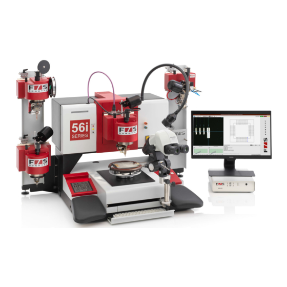
Model 56XXi 4) Model 56XXi Figure 4.0. - 1 Model 56xxi IMPORTANT! Some illustrations and detailed descriptions in this manual may differ from the actual machine if the hard- ware of the machine has been customized. The following chapters assume a basic knowledge of electronics, especially of wire bonding technology. You can find more information about wire bonding on the Internet. -
Page 16: Overview Of The Multifunction Device
Model 56XXi Overview of the multifunction device Figure 4.1. - 1 Overview multifunction device Control Elements 4.2.1 Main switch (with emergency stop function) Serves to switch the machine on/off. 4.2.2 EMERGENCY-STOP Button The machine stops immediately when the EMERGENCY-STOP button is pressed. 4.2.3 Monitor All process-relevant information is displayed to the user on the monitor. -
Page 17: The Axes Of The Motion System
Model 56XXi 4.2.7 Keypad The machine is operated using the keys on the keypad. Process-relevant functions can be started with them. 4.2.8 PC Keyboard / Service Keyboard Inputs can be made with the PC keyboard. 4.2.9 EBP-Connection The user can make a conductive connection to the machine at the EBP connector to prevent the destruction of electronic components caused by electrical charges. -
Page 18: Bond Heads
Model 56XXi Bond heads Terminoligy Wire spool holder protection and support of the used wire spool. Camera a live camera image is used when positioning all process relevant positions. head clamp / bond head holder fixes the bond head to the base machine. Wire guide guides the wire from the wire spool to the tip of the bonding tool. - Page 19 Model 56XXi 4.4.2 5630i Thin-Wire Head The bonding head 5630i is designed for the ultrasonic wedge-wedge welding process. Bond wires with a diameter of 17µm to 75µm (0.7mil to 3mil) can be welded on suitable surfaces. Figure 4.4. - 1 Thin-Wire Head 5630i 4.4.3 5632i Thin-Wire Head The 5632i Deep Access Bond Head features a special design of the bond head.
- Page 20 Model 56XXi 4.4.4 5650i / 5650i HR Heavy-Wire Head The heavy wire bonding head is designed for aluminum wires with a thickness of 100 µm to 500 µm (4 mil to 20 mil). In contrast to the thin wire bonding heads, the heavy wire bonding head has a knife built in (front or back cut possible). The finished bonded wire is cut off here because the wires are too thick to tear.
-
Page 21: Transport And Installation
Transport and Installation 5) Transport and Installation DANGER! Wear safety gloves and safety shoes during transport and installation. Transport / Packaging The machine is delivered in its original packaging and with transport protection. For any further transport, the trans- port safety device (especially for bond heads) must be reattached and all moving parts must be securely fixed. Machines or bond heads should only be shipped in the designated boxes or cases. -
Page 22: Electrical Connection
Transport and Installation IMPORTANT! Before commissioning, make sure that the wiring is complete. Electrical Connection The bonder is connected to the power supply with a conventional IEC 60320-1 C 13 power cable. Figure 5.5. - 1 Connections DANGER! >> Work on the electrical supply may only be carried out by qualified electricians. >>... -
Page 23: Vacuum Connection
Transport and Installation 5.5.1 Setting the Supply Voltage Basically the operation with 2 different mains voltages is possible: >> 115V >> 230V The voltage is set ex works to the specifications given in the order and may not be changed by the customer without authorization. -
Page 24: Basic Functions
Basic Functions 6) Basic Functions IMPORTANT In order to use the machine properly and safely, make sure that you have read and understood chapter 1 (General Information) and chapter 2 (For Your Safety) before. Before each commissioning, make sure that the machine is in perfect, safe operating condition and that all safety precautions are observed! After switching on the main switch, the operating system boots and you will find a standard Windows TM interface. -
Page 25: The Most Important Functions
Basic Functions User Interface Main Menue Main Tool Bar Expiration Quick Access Live Video Plot Program Bond Results Status Console Plot Program Toolbar The Most Important Functions 6.1.1 Main Menue File. Load & save files, close application Page. Includes program specific and global machine parameters. In the menu <Page> only values are entered. However, automatic movements are never executed or actuators controlled. -
Page 26: Simple Actions
Basic Functions 6.1.6 Bond Results (DLC - Deformation Limit Control) The deformation of the wire at the welding point created during the bonding process is graphically displayed. 6.1.7 Status and Console Process related information and notes. 6.1.8 Plot Program Toolbar It contains buttons which interact with the elements displayed in <Plot Program>. -
Page 27: Frequently Returning Operation
Basic Functions Feed in wire and bond. The <Feed In Position> is approached with the button In this position those functions are available, which facilitate the threading of the bonding wire. Helpful for threading the wire is the activation of the ultrasound via the keypad. This is possible by pressing the <Enter>... -
Page 28: Create A Bond Program
Basic Functions Figure 6.3. - 1 Position specification The joystick is active in the Positions input window and can therefore be used to move to the desired position. With <Store Trace> (keypad) the current position is permanently taught in. By simultaneously pressing the Ctrl+Shift and cursor keys on the PC keyboard, the XY axes can be moved at fine pitch intervals in <micron steps>. -
Page 29: The Single Wire Mode
The Single Wire Mode 7) The Single Wire Mode A wire defines a joint made by friction welding, which has a welding point at the beginning and at the end and where the welding points are connected by an arc of wire. This wire arc thus creates an electrically conductive connection between the two welding points. -
Page 30: Bonding In Single Wire Mode
The Single Wire Mode Bonding in Single Wire Mode The machine mode must be set to <Single Wire>. Pressing the <Bond> key on the keypad opens the Single Wire dialog. The individual segments of a wire connection are represented in the editing window by the respective tabs. Figure 7.1. -
Page 31: Working In Single Step Mode (Step Mode)
The Single Wire Mode Working in Single Step Mode (Step Mode) In Step Mode, the bond process is carried out in individual steps, so that the process can be precisely analyzed and observed. The Step Mode can be activated and deactivated at any time with the <Step> key on the keypad. If the Step Mode is activated, the automatic motion sequence is interrupted immediately. -
Page 32: Process Optimization
Process Optimization 8) Process Optimization If no bond was created or the shape of the bond or loop does not meet the specifications, the process settings must be changed or adjusted after the first bond attempt. When bonding, the following parameters will be primarily decisive in terms of adhesion and the shape of the welded joint: >>... - Page 33 Process Optimization 8.1.3 Bondforce The bondforce is primarily dependent on the wire diameter used. In the thin wire range (18-75µm diameter) one can assume that the suitable setting of the bondforce (for bondable surfaces) will be approximately equal to the wire dia- meter.
-
Page 34: Loop
Process Optimization 8.1.5 Deformation Limit Control The deformation measured during bonding is displayed on the monitor as a graphic. An upper and lower limit value for the measured deformation can be defined (<Page><GlobalSettings><DLC>) and the machine can be stopped au- tomatically if the deformation exceeds or falls below these limits. - Page 35 Process Optimization IMPORTANT! If there is too much friction on the wire during the reverse movement in the bonding tool, the wire can tear. Therefore, the heights and travels (XYZ) must be set in such a way that friction is avoided as far as possible, and the wire is bent during the reverse movement, but no other wire is pulled through the bonding tool (e.g.: set reverse height lower than presign).
- Page 36 Process Optimization In this case, the second reverse movement also uses the above settings. A second reverse movement is possible in principle, but it is also rather unusual for ball-wedge bonding. 8.2.2 Expert Loop The Expert Loop has its own settings and it differs from the Standard Loop because, for example, the difference in height between the first and second bond points is taken into account when calculating the loop height.
- Page 37 Process Optimization 8.2.3 Termination Termination is the cutting of the wire at the end of a wire connection. This is done in different ways in different bonding processes. In the case of the thin wire, the wire is torn, either only the clamp is moved <Feed Limiter>...
-
Page 38: Multiwire Program
Multiwire Program 9) Multiwire Program The Multiwire mode works similar to the Single Wire mode. However, it is possible to program several wires and to process them automatically. A multiwire program has chips in addition to wires. Figure 9.0. - 1 Chips Chip. -
Page 39: Creating Wires With Learn Wire
Multiwire Program If <1 Point> or <2 Points> is selected for Adjustment, the position of the respective chip is defined by one or two Ad- just Points. To do this, you have to move to a significant structure with the joystick and then save this position with <Store Trace>. -
Page 40: Normalize Program
Multiwire Program Column Figure 9.3. - 1 Module Matrix Original First Column First Row Last Column Last Row Modules can only be duplicated if the entire component is repeated several times. If only individual areas or chips on a component are identical, it is better to work with copies. See Copy Paste. Normalize Program With Normalize program, after an adjustment process all chip and bond positions are moved as if the program had been trained at this position. -
Page 41: Change Bondprogram With Plot Program (Show Program)
Multiwire Program 9.6.2 MoveProgram Z <MoveProgram Z> is used if the part holder has been changed and therefore the whole bond program has to be mo- ved to Z It is assumed that all heights have already been measured. The function is called under <Mode> <MovePro- gramZ>. - Page 42 Multiwire Program chip are also selected. Ctrl + mouse click: add/exclude Ctrl + mouse drag: Invert selection in rectangle Ctrl + Shift+ mouse drag: Select (whether it is already selected or not) 9.7.1 Change Wire Group This function is useful if you want to change a parameter on several wires. For this purpose activate the mode <Select Wires>...
- Page 43 Multiwire Program 9.7.2 Save and Load Wire Parameter If you select wires with you can load or save parameters with the right mouse button <Edit Wires> <Load Parameters> or <Save Parame- ters>. Parameters can be transferred from "Single Wire" or a library. 9.7.3 Copy Paste <Copy Paste>...
-
Page 44: Production Operation
Multiwire Program 9.7.6 Repeat Wire Ideal for duplicating a single wire. With <Repeat Wire> a separate XY offset is defined for each bond position. To do this, activate the mode and click on a wire. Then select <Repeat Wire> with the right mouse button or <Mode> <Repeat Wire>. Specify the number of repetitions with <Repeat Count>... -
Page 45: Quality Control
Multiwire Program It is also possible to create only single chains or only stitch on ball at 5x10 under 9.8.3 Reset Alignment <Mode> <Reset Alignment> discards the adjustment data from the last Adjust operation. Afterwards a new adjust- ment can be performed. Quality control 9.9.1 Deformation Limit Control See Chapter 8.1.5. - Page 46 Multiwire Program To ensure an exact manual positioning of the crosshairs by the operator, the adjustment points should be selected in such a way that the crosshairs run at a clearly visible corner. The model area should be moved so that a structure actually occurs only once in the search area.
-
Page 47: Calibrations
Calibrations 10) Calibrations All calibrations listed here are made during commissioning by F&S Bondtec. Changes should only be made by the user after consultation with F&S Service! IMPORTANT! All calibrations are permanently written to the memory unit of the bond head only after closing the soft- ware. -
Page 48: Camera Offset
Calibrations 10.3 Camera Offset Calculation of the deviation between optical axis (crosshairs) and mechanical axis (bond head, bond tool). >> Position the crosshairs with a joystick over a free bondable area on the substrate. >> Press Store Trace button to save the position and measure the height of the surface. >>... -
Page 49: Adjustment Work On The Bondhead
Adjustment Work on the Bondhead 11) Adjustment Work on the Bondhead The following activities assume that Chapter 1 (General Information) and Chapter 2 (For Your Safety) have been read and understood. 11.1 Bonding Wire DANGER! Avoid any skin contact with the bonding wire and all wire-carrying parts, as contamination such as a fin- gerprint can lead to a bad quality of the bond. - Page 50 Adjustment Work on the Bondhead Figure 11.1. - 2 Wire Path 5630i Figure 11.1. - 3 Wire Path 5632i © 2020 F&S BONDTEC Semiconductor GmbH. All rights reserved.
-
Page 51: Bond Tool
Adjustment Work on the Bondhead With the 5650i heavy wire head, the wire is guided in a silicone tube up to the tool. 11.2 Bond tool 11.2.1 Bond tool Installation / Change IMPORTANT! The bonding tool is a consumable item and must be replaced at the latest when the bonding quality decli- nes noticeably or after a selected number of bonds. -
Page 52: Mechanical Settings
Adjustment Work on the Bondhead 11.3 Mechanical Settings 11.3.1 Bracket Settings 5610 Figure 11.3. - 1 Bracket settings 5610i 1. Set FlameOff Lance vertically. >> Release clamping screw >> Set holder with grub screw at the top 2. Set the clamp horizontally. Figure 11.3. - Page 53 Adjustment Work on the Bondhead Adjust FlameOff Lance . Figure 11.3. - 3 FlameOff Lance 5610i 1. Loosen fastening screw. >> Lance can be moved inwards and outwards 2. Loosen the clamping screws. >> Lance holder can be moved forward and backward >>...
- Page 54 Adjustment Work on the Bondhead 1. Adjust clamp. >> Release clamping screw >> Use the thumbscrew to move the clamp sideways 2. Move clamp uni vertically. >> Loosen clamping screw >> Adjusting the height of the clamp >> Retighten clamping screw Figure 11.3.
- Page 55 Adjustment Work on the Bondhead 1. Adjust distance of lower wire clamp. >> Turn the fastening screw of the spring tighter/ looser 2. Adjust wire guide. >> Loosen clamping screw of the eccentric >> Turn eccentric >> This changes the distance between the wire clamp and the bonding tool. 11.3.4 Knife Settings 5650i+HR Figure 11.3.
-
Page 56: Cleaning Of The Components
Adjustment Work on the Bondhead 11.3.5 Bracket Settings Heavy Ribbon Kit Figure 11.3. - 1 Bracket settings HR-Kit 1. Opening width wire clamp. >> Open locknut >> Adjust stop 2. Adjust the force of the wire clamp. 3. Distance to the tool. >>... - Page 57 Adjustment Work on the Bondhead 11.4.2 Wire Guide The wire guide should be cleaned monthly. >> Soak a pipe cleaner with pure alcohol or acetone. >> Pull the pipe cleaner several times through the feed channel and the wire guide tube. >>...
Need help?
Do you have a question about the 56 i Series and is the answer not in the manual?
Questions and answers