Table of Contents
Advertisement
Quick Links
Advertisement
Table of Contents

Related Manuals for TAG MCLAREN AUDIO 100 5R Series


Summary of Contents for TAG MCLAREN AUDIO 100 5R Series
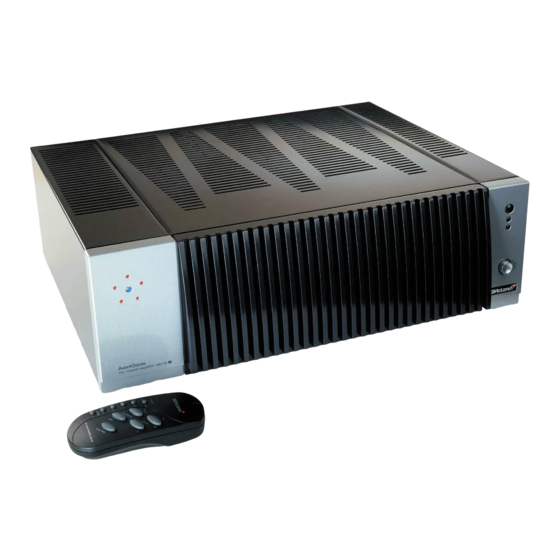
- Page 1 service manual amplifier 100x5R...
- Page 2 TAG McLaren Audio Limited. This manual is for the exclusive use of TAG McLaren Audio, its approved distributors and approved UK service agents. No part of this manual shall be transferred to any other party without the express written permission of TAG McLaren Audio Limited.
-
Page 3: Table Of Contents
index safety and servicing notes Safety precautions ........1 Electrostatic discharge precautions . - Page 4 10.4 100X5R IR BUS PCB ........26 10.5 100X5R LED PCB .
-
Page 5: Safety And Servicing Notes
To prevent ESD damage to TAG McLaren Audio units, it is necessary to follow these guidelines. Prepare work area. Place an ESD protective mat on the bench, strapped to the protective earth circuit. -
Page 6: Soldering
1.3 Soldering How to de-solder components Components should be removed, wherever possible, using a de-soldering tool. Be careful not to damage tracks and pads by applying too much pressure. How to make good solder joints Ensure surfaces are clean. Keep soldering iron clean and wetted with solder. Use an appropriate bit. - Page 7 Cleaning up after soldering Flux is very corrosive. Remove with IPA (propan-2-ol) before completing the job. Remove any solder balls and splashes from the unit. Check all new solder joints and ensure all PCBs are clean before replacing covers. After replacing covers, clean the case and any display windows with a damp cloth. Do not use any organic solvents.
-
Page 8: Front And Rear Panel Layouts
2.0 front and rear panel layouts 2.1 front panel controls 2.2 rear panel connections F3 series 100X5R service manual... -
Page 9: Disassembly Instructions
3.0 disassembly instructions To protect the unit, place on 2 foam blocks during disassembly and reassembly. 3.1 removing case and fascia Remove cover Place unit on bench - rear panel facing you Remove cover’s 9 fixing screws Pull cover towards the rear of the unit gently whilst carefully pulling bottom sides out a little Lift cover slightly at the rear panel, then pull cover gently towards you Remove front panel assembly... - Page 10 F3 series 100X5R service manual...
-
Page 11: Technical Outline
4.0 technical outline 4.1 technical description Introduction The 100x5R is a five channel amplifier, featuring five identical and independent power amplifier modules and a microprocessor control board (wth associated input and output connections). Each of the five amplifiers features its own mains transformer, power supply components and heatsink assembly. - Page 12 Clean relay switches OFF After a short delay, dirty relay switches OFF This allows the dirty relay to handle all of the ‘hard’ load conditions, with the clean relay being protected from surges and inductive spikes. During listening evaluation it was found that relay contacts have an effect on subjective audio quality.
- Page 13 4.3 Description of pins of J1 Net Name Type Description P5V_A supply +5VDC DMute_LED open collector + 1K0 mute LED D_IR_Rx_LED open collector + 1K0 IR receive LED DGND ground digital 0V DGND ground digital 0V IR_IN micro P3.2 IR remote input P5V_A supply +5VDC...
-
Page 14: 100X5R Block Diagram
FaultC5 schmitt trigger + 10K channel 5 fault signal pulldown DGND ground digital 0V DGND ground digital 0V MRelay5 open collector channel 5 mute relay Present5 micro P5.1 channel 5 present (active low) none Tag Bus ground + 100uH + 100R none Emitter of Q13 to MCD4 (P0L.4) -
Page 15: Functional Tests
5.0 functional tests These notes are provided to assist you in servicing the 100X5R amplifier. F3 series 100X5R service manual... -
Page 16: Fault Finding Flow Chart
5.1fault finding flow chart: 5.2 Test equipment required Equipment Specification Digital Multimeter Accuracy better than 0.5% in V and mV ranges Oscilloscope Bandwidth >100 MHZ Various Leads With faulty modules the uC control can be bypassed by disconnecting the 6-way ribbon from the Module Under Test (MUT). -
Page 17: Biasing Modules
Fuses should not blow in normal use. A blown fuse is probably an indication of a more serious problem. Before replacing the fuse check that the circuit it is connected to is not a short circuit. If it is this will need to be corrected first. A short circuit in the transformer primary windings could cause the mains fuse to blow. -
Page 18: Adding Modules
5.5 Adding Modules In order to increase the number of modules in a units the upgrade pack F3 100x1 xxx (where xxx is the voltage) is required. remove cover, front panel and uC PCB as above. Remove the blanking plate where the module is to be inserted: No of Position channels... -
Page 19: Performance Tests
6.0 performance tests 6.1 Test equipment required Equipment Specification Signal Generator 20 Hz to 20 kHZ 100mV - 2V rms Distortion Analyser 20 Hz - 20 kHz Distortion measurement 0.001% or better Voltage measurement 0.003 V to 10 V dB scale -90 dB to +10 dB Digital Multimeter Accuracy better than 0.5% in V and mV ranges Oscilloscope... - Page 20 6.2.4 Frequency Distortion Measure signal level on distortion response analyser analyser. output: 1kHz, 1 V rms Set as 0 dB reference measurement mode:signal 20Hz 0.0dB ±0.02 level. 20kHz -0.16dB ±0.05 6.2.5 Measure Distortion Leave AUDIO OUTPUT connected distortion analyser to distortion analyser input. output: 20Hz - Measure THD on distortion 20kHz, 1 V...
-
Page 21: Upgrading Software
7.0 upgrading software 7.1 Equipment required Equipment Specification Running Windows 95/98/NT and TMA Upgrade Wizard software TAGtronic bus F3 TAGTRONIC adaptor 7.2 Upgrading software procedure Action Test Details Equipment 8.2.1 Switch off AC power button 8.2.2 Insert red RJ- 45 plug into ‘in’ TAGtronic bus adaptor socket of... -
Page 22: Diagnostics
If none of these is the case, then there is possibly a fault with the 100X5R. Please note the error message and contact TAG McLaren Audio for guidance. 8.2 Resetting parameters If any channels are caused to go into protect such that a fault is detected while the output relay is open, the microprocessor will ensure that channel will not power up again. -
Page 23: Circuit Schematics
9.0 circuit schematics 9.1 100X5R LED PCB Sheet 1 of 1: 283 LED PCB (SCH28303-01-01) 9.2 100X5R IR PCB Sheet 1 of 1: IR RECEIVER (SCH28204-01-01) F3 series 100X5R service manual... -
Page 24: 100X5R Uc Pcb
9.3 100X5R MICROCONTROLLER PCB Sheet 1 of 3: 2 8 3 M I C R OCON T R O L L E R P C B (SCH2 8 2 0 6 - 01-03) F3 series 100X5R service manual... - Page 25 Sheet 2 of 3: 283 MICROCONTROLLER PCB (SCH28206-02-03) F3 series 100X5R service manual...
- Page 26 Sheet 3 of 3: 283 MICROCONTROLLER PCB (SCH28206-03-03) F3 series 100X5R service manual...
- Page 27 F3 series 100X5R service manual...
- Page 28 9.4 100X5R AMPLIFIER MODULE PCB Sheet 1 of 2: 283 AMPLIFIER SCHEMATIC (SCH28301-01-04) F3 series 100X5R service manual...
- Page 29 Sheet AMPLIFIER SCHEMATIC (SCH28301-02-04) F3 series 100X5R service manual...
-
Page 30: 100X5R Tag Bus Pcb
9.5 100X5R TAG BUS PCB F3 series 100X5R service manual... - Page 31 10.0 printed circuit board layout 10.1 100X5R AMPLIFIER PCB Amplifier Module PCB F3 series 100X5R service manual...
- Page 32 10.3 100X5R MICROCONTROLLER PCB (4 layer - not including inner ground & +5V planes) 10.4 IR PCB 10.5 LED PCB 10.3 TAG BUS F3 series 100X5R service manual...
- Page 33 11.0 technical data 11.1 100X5R Technical Specifications Specification Load Conditions units Output power continuous >100 short term >150 short term >190 Channel Balance <0.2 Sensitivity .103 ± 0.02 Gain 1kHz 28.8 ± 0.2 Input impedance >20 Signal/Noise ref 0dBW 20Hz - 20kHz BW >90 ref 0dBW ‘A’...
- Page 34 The 100X5R meets or exceeds the following legal requirements: 89/336/EEC EMC Directive (as amended by 93/23/EEC) directives 73/23/EEC Low Voltage Directive (as amended by 93/23/EEC) TAG McLaren Audio Ltd The Summit, Latham Road Huntingdon, Cambs PE18 6ZU United Kingdom Telephone +44 (0)1480 415600 +44 (0)1480 52159 E-Mail helpdesk@tagmclarenaudio.com...
Need help?
Do you have a question about the 100 5R Series and is the answer not in the manual?
Questions and answers