Table of Contents
Advertisement
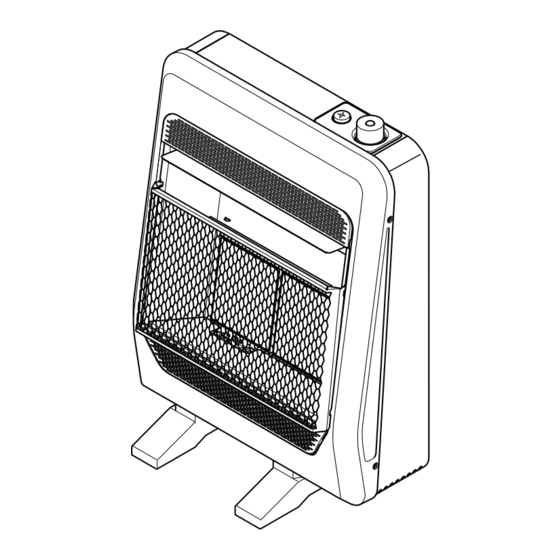
VENT-FREE GAS
WALL HEATER
OWNER'S OPERATION AND
INFRARED MODELS
B10TNIR-B, B10TPIR-B
B20TNIR-BB, B18TPIR-BB
B30TNIR-BB, B28TPIR-BB
INSTALLATION MANUAL
PFS
WARNING: If the information in this manual is not
followed exactly, a fire or explosion may result causing
property damage, personal injury or loss of life.
®
US
Advertisement
Table of Contents

Related Manuals for Bluegrass Living B10TNIR-B

Summary of Contents for Bluegrass Living B10TNIR-B
- Page 1 VENT-FREE GAS WALL HEATER OWNER’S OPERATION AND INFRARED MODELS B10TNIR-B, B10TPIR-B B20TNIR-BB, B18TPIR-BB B30TNIR-BB, B28TPIR-BB INSTALLATION MANUAL ® WARNING: If the information in this manual is not followed exactly, a fire or explosion may result causing property damage, personal injury or loss of life.
- Page 2 — Do not store or use gasoline or other flammable vapors and liquids in the vicinity of this or any other appliance. — WHAT TO DO IF YOU SMELL GAS • Do not try to light any appliance. • Do not touch any electrical switch; do not use any phone in your building.
-
Page 3: Table Of Contents
Questions, problems, missing parts? Before returning to your retailer, call our customer service department at 1-866-762-4050, 8:00 am - 4:30 pm CST, Monday through Friday or email service@bluegrassliving.com TABLE OF CONTENTS Safety ............3 Operation ..........16 Qualified Installing Agency ......4 Electrical Connection ....... 18 Specifications .......... - Page 4 This appliance may be installed in an aftermarket,* permanently located, manufactured (mobile) home, where not prohibited by local codes. This appliance is only for use with the type of gas indicated on the rating plate. This appliance is not convertible for use with other gases. * Aftermarket: Completion of sale, not for purpose of resale, from the manufacturer.
-
Page 5: Safety
SAFETY 2000458-01A www.bluegrassliving.com... - Page 6 WARNING: Do not attempt to access or change the setting of the fuel selection means. Access to and adjustment of This appliance is only for use the fuel selection means must with the type of gas indicated only performed rating plate.
- Page 7 agent is added to the gas. The odor helps you detect a gas leak. However, the odor added to the gas can fade. Gas may be present even though no odor exists. SAFETY 3. This heater needs fresh air ventilation to WARNING: Make sure grill run properly.
-
Page 8: Qualified Installing Agency
SPECIFICATIONS MODEL B10TNIR-B B10TPIR-B Ignition Piezo Piezo Gas Type Natural Propane/LP BTU (available) 10,000 10,000 Pressure Regulator 6"... -
Page 9: Product Features
MODEL B30TNIR-BB B28TPIR-BB Ignition Piezo Piezo Gas Type Natural Gas Propane/LP BTU (available) 30,000 28,000 Pressure Regulator 6" W.C. 10" W.C. Setting Inlet Gas Pressure* Maximum Maximum 14" 10.5" (inches of water) Minimum 7" Minimum 11" Heater Weight 25.8 lbs 25.8 lbs Shipping Weight 30 lbs... -
Page 10: Unpacking
Install and use heater with care. Follow all local codes. In the absence of local codes, use the latest edition of The National Fuel Gas Code, ANSI Z223.1/NFPA 54*. *Available from: American National Standards Institute, Inc. 25 West 43rd Street New York, NY 10036 National Fire Protection Association, Inc. -
Page 11: Air For Combustion And Ventilation
Water vapor is a by-product of gas heaters are recommended as supplemental combustion. An unvented room heater heat (a room) rather than a primary heat produces approximately one (1) ounce (30 source entire house). most supplemental heat applications, the water vapor does not create a problem. - Page 12 WARNING: This heater shall not be installed in a room or Today’s homes are built more space unless required energy efficient than ever. New volume of indoor combustion materials, increased insulation and air is provided by the method new construction methods help reduce heat loss in homes.
- Page 13 IMPORTANT: Do not provide openings for inlet or outlet air into attic if attic has a thermostat-controlled power vent. Heated air all appliances in both spaces. 2000458-01A www.bluegrassliving.com...
-
Page 14: Installation
NOTICE: This heater intended supplemental heat. Use this INSTALLATION heater along with your primary CAUTION: This heater heating system. Do not install creates warm currents. this heater as your primary These currents move heat to heat source. If you have a wall surfaces next to heater. - Page 15 INSTALLATION CLEARANCES TO COMBUSTIBLES Carefully follow the instructions below. This heater is a freestanding unit designed to be mounted on a wall or set on a base. Figure 4 - Mounting Clearances as Viewed From Front of Heater LOCATING HEATER REMOVING FRONT PANEL This heater is designed to be mounted on a 1.
- Page 16 INSTALLATION Decide which method better suits your " " Min. needs. Either method will provide a secure hold for the mounting bracket. Marking Screw Locations Only Insert Mounting 1. Tape mounting bracket to wall where 16 " Screws Through Last Min.
- Page 17 INSTALLATION 2. Place mounting bracket onto wall. Line Placing Heater On Mounting Bracket up last hole on each end of bracket with 1. Locate two horizontal slots on back panel holes drilled in wall. of heater (see Figure 10). 3. Insert mounting screws through bracket 2.
- Page 18 INSTALLATION Note: Do not replace front panel at this time. Replace front panel after making gas connections and checking for leaks. Screw Figure 11 - Installing Bottom Mounting Hole Screws INSTALLING BASE FEET 1. Align screw holes in base feet to the bottom of the heater.
- Page 19 INSTALLATION CAUTION: For propane/LP gas, Never connect heater CONNECTING TO directly to the gas supply. This GAS SUPPLY heater requires an external regulator (not supplied). Install the external regulator between the heater and gas supply. Gas supplier provides external regulator for natural gas. The installer provides the external regulator for propane/LP gas.
- Page 20 INSTALLATION WARNING: qualified service technician must Before installing connect heater to gas supply. heater, make sure you Follow all local codes. have the items listed below: WARNING: This appliance • piping (check requires a 3/8" NPT (National local codes) • Pipe Thread) inlet connection sealant (resistant to natural...
- Page 21 INSTALLATION IMPORTANT: Install an equipment shutoff valve in an accessible location. The equipment shutoff valve is for turning on or shutting off the gas to the appliance. Apply pipe joint sealant lightly to male Pointing the vent down protects it from threads.
- Page 22 INSTALLATION CHECKING GAS CONNECTIONS WARNING: Test all gas WARNING: Never use an piping and connections for open flame to check for a leak. leaks after installing Apply a mixture of liquid soap servicing. Correct all leaks at and water to all joints. If once.
- Page 23 INSTALLATION Test Pressures Equal To or Less Than 1/2 PSIG (3.5 kPa) 1. Close equipment shutoff valve (see Fig- Gas Valve ure 16). 2. Pressurize supply piping system by either using compressed air or opening gas supply valve. 3. Check all joints from gas supply (see Fig- ure 17 or 18) to equipment shutoff valve.
- Page 24 INSTALLATION Natural Gas PRESSURE TESTING HEATER GAS CONNECTIONS 1. Open equipment shutoff valve (see Fig- 5. Correct all leaks at once. ure 16, page 15). 6. Light heater (see Lighting Instructions on 2. Open gas supply tank valve. page 16). Check all other internal joints 3.
- Page 25 INSTALLATION 5. Turn control knob counterclockwise to the PILOT position. Press in control knob for five (5) seconds. Note: The first time that the heater is operated after connecting the gas supply,the control knob should be pressed for about thirty (30) seconds. This will allow air to bleed from the gas system.
- Page 26 OPERATION 6. With control knob pressed in, push down and release ignitor button. This will light pilot. The pilot is attached to the front of burner. The pilot can be seen through the grill. If needed, keep pressing ignitor button until pilot lights. Note: If pilot does not stay lit, refer to Troubleshooting, Also contact...
- Page 27 Turn control knob clockwise to the (pilot stays lit) OFF position. Turn control knob clockwise to the PILOT position. Do not use this heater if any MANUAL LIGHTING PROCEDURE part of it has been under water. Remove lower front panel. Keep Immediately call a qualified service technician to inspect...
- Page 28 Any electrical re-wiring of this appliance must be WARNING: Never attempt to done by a qualified electrician. This wiring must service heater while be done in accordance with local codes and/or in Canada with the current CSA C22.1 plugged in, operating, or hot. Canadian Electrical Code,...
- Page 29 If burner flame pattern is incorrect, as shown Figure 24 - Incorrect Pilot Flame Pattern in Figure 25 BURNER FLAME PATTERN • turn heater off (see To Turn Off Gas to Appliance, page 17) • see Troubleshooting pages 21 through 23. Notice: Do not mistake orange flames with yellow tipping.
- Page 30 BURNER INJECTOR HOLDER AND PILOT AIR INLET HOLE We recommend that you clean the unit every directions on the can, you could damage the pilot assembly. 2,500 hours of operation or every three months. We also recommend that you keep 1.
- Page 31 TROUBLESHOOTING WARNING: If you smell gas: • Shut off gas supply. • Do not try to light any appliance. • Do not touch any electrical switch; do not use any phone in your building. • Immediately call your gas supplier from a neighbor’s phone. Follow the gas supplier’s instructions.
- Page 32 TROUBLESHOOTING When ignitor button is 1. Gas supply is turned off or 1. Turn on gas supply or open equipment shutoff valve is equipment shutoff valve. pressed in there is a closed. spark at ODS/pilot but 2. Control knob not fully 2.
- Page 33 TROUBLESHOOTING Delayed ignition of 1. Manifold pressure is too 1. Contact local gas supplier. burner(s). low. 2. Clean burner (see Care and 2. Burner orifice is clogged. Maintenance, page 20). Burner backfiring during 1. Burner orifice is clogged or 1. Clean burner orifice (see damaged.
- Page 34 TROUBLESHOOTING Heater produces 1. Heater is burning vapors 1. Ventilate room. Stop using from paint, hair spray, glues, odor causing products while unwanted odors. etc. IMPORTANT heater is running. statement, page 20. 2. Locate and correct all leaks 2. Gas leak. See Warning (see Checking Statement at the top of page...
- Page 35 TECHNICAL SERVICE You may have further questions about installation, operation, or troubleshooting. If so, contact Bluegrass Living, Inc. at 1-866-762-4050. When calling, please have your model and serial numbers of your heater ready. SERVICE HINTS When Gas Pressure Is Too Low •...
- Page 36 PARTS MODELS B10TNIR-B, B10TPIR-B www.bluegrassliving.com 200458-01A...
- Page 37 PARTS 2000458-01A www.bluegrassliving.com...
- Page 38 PARTS MODELS B10TNIR-B, B10TPIR-B This list contains replaceable parts for your heater. When ordering replacement parts, follow the instructions listed under Replacement Parts on page 30 of this manual. ITEM B10TNIR-B B10TPIR-B DESCRIPTION Back Body Panel 161132-01 161132-01 Mounting Bracket...
- Page 39 PARTS PART AVAILABLE - NOT SHOWN 161607-01 161607-01 Hardware Package ** Not a field replaceable part. 2000458-01A www.bluegrassliving.com...
- Page 40 PARTS MODELS B20TNIR-BB, B18TPIR BB, B30TNIR-BB, B28TPIR-BB 30,000 BTU/Hr Heater Shown www.bluegrassliving.com 200458-01A...
- Page 41 PARTS 2000458-01A www.bluegrassliving.com...
- Page 42 PARTS MODELS B20TNIR BB, B18TPIR-BB This list contains replaceable parts for your heater. When ordering replacement parts, follow the instructions listed under Replacement Parts on page 30 of this manual. ITEM B20TNIR-BB B18TPIR-BB DESCRIPTION Back Body Panel 161132-01 161132-01 Mounting Bracket 161133-01 161133-01 Piezo Ignitor...
- Page 43 PARTS 161607-01 161607-01 Hardware Package ** Not a field replaceable part. MODELS B30TNIR BB, B28TPIR-BB This list contains replaceable parts for your heater. When ordering replacement parts, follow the instructions listed under Replacement Parts on page 30 of this manual. ITEM B30TNIR-BB B28TPIR-BB DESCRIPTION...
- Page 44 PARTS BF09B-BK BF09B-BK Base Feet PART AVAILABLE - NOT SHOWN 161607-01 161607-01 Hardware Package ** Not a field replaceable part. www.bluegrassliving.com 200458-01A...
-
Page 45: Warranty
REPLACEMENT PARTS Note: Use only original replacement parts. This will protect your warranty coverage for parts replaced under warranty. PARTS UNDER WARRANTY • Model and serial number of your heater Contact authorized dealers of this product. If they can’t supply original replacement parts, •... - Page 46 _______ _________________________________________________________ _______ _________________________________________________________ _______ _________________________________________________________ _______ _________________________________________________________ _______ _________________________________________________________ _______ _________________________________________________________ _______ _________________________________________________________ _______ _________________________________________________________ _______ _________________________________________________________ _______ _________________________________________________________ _______ _________________________________________________________ _______ _________________________________________________________ _______ www.bluegrassliving.com 200458-01A...
- Page 47 _________________________________________________________ _______ _________________________________________________________ _______ _________________________________________________________ _______ _________________________________________________________ _______ _________________________________________________________ _______ _________________________________________________________ _______ _________________________________________________________ _______ _________________________________________________________ _______ _________________________________________________________ _______ _________________________________________________________ _______ _________________________________________________________ _______ WARRANTY KEEP THIS WARRANTY Model _______________________________ Serial No. ____________________________ 2000458-01A www.bluegrassliving.com...
- Page 48 This is Bluegrass Living’s exclusive warranty, and to the full extent allowed by law; this express warranty excludes any and all other warranties, express or implied, written or verbal and limits the duration of any and all implied warranties, including warranties of merchantability and fitness for a particular purpose to one (1) year on new products and 30 days on factory reconditioned products from the date of first purchase.
- Page 49 1-866-762-4050 08/19 2000458-01A www.bluegrassliving.com...
Need help?
Do you have a question about the B10TNIR-B and is the answer not in the manual?
Questions and answers