HP Compaq dc7600 USDT Hardware Reference Manual
Business pc ultra-slim desktop model
Hide thumbs
Also See for Compaq dc7600 USDT:
- Quickspecs (61 pages) ,
- Management manual (48 pages) ,
- Getting started manual (46 pages)
Table of Contents
Advertisement
Quick Links
Hardware Reference Guide
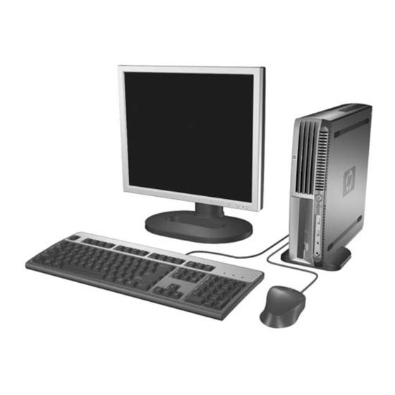
HP Compaq Business PC
dc7600 Ultra-Slim Desktop Model
Document Part Number: 383421-001
May 2005
This guide provides detailed information on the features and use of
the HP Compaq dc7600 Ultra-Slim Desktop, and includes
instructions for removing and replacing internal components.
Advertisement
Table of Contents

Related Manuals for HP Compaq dc7600 USDT


Summary of Contents for HP Compaq dc7600 USDT
- Page 1 HP Compaq Business PC dc7600 Ultra-Slim Desktop Model Document Part Number: 383421-001 May 2005 This guide provides detailed information on the features and use of the HP Compaq dc7600 Ultra-Slim Desktop, and includes instructions for removing and replacing internal components.
- Page 2 Microsoft and Windows are trademarks of Microsoft Corporation in the U.S. and other countries. The only warranties for HP products and services are set forth in the express warranty statements accompanying such products and services. Nothing herein should be construed as constituting an additional warranty. HP shall not be liable for technical or editorial errors or omissions contained herein.
-
Page 3: Table Of Contents
Choose Tower or Desktop Configuration ........1–6... - Page 4 Shipping Preparation ........... E–3 Index www.hp.com Hardware Reference Guide...
-
Page 5: Product Features
Standard Configuration Features The Ultra-Slim Desktop computer comes with features that may vary depending on the model. For a complete listing of the hardware and software installed in the computer, run the diagnostics utility. Instructions for using this utility is provided in the Troubleshooting Guide on the Documentation and Diagnostics CD. -
Page 6: Front Panel Components
Microphone Connector Headphone Connector ✎ Any USB device (including keyboard and mouse) can be connected to any USB connector. 1–2 Universal Serial Bus (USB) Connector (2) Power On Light Hard Drive Activity Light Dual-State Power Button www.hp.com Hardware Reference Guide... -
Page 7: Rear Panel Components
Hardware Reference Guide n RJ-45 Network Connector l Parallel Connector c Monitor Connector Y Line-Out Connector (green) (for powered devices) j Line-In Audio Connector (blue) c Digital Video Interface (DVI–D) Monitor Connector (optional) www.hp.com Product Features 1–3... -
Page 8: Standard Keyboard Components
Logo Keys* combination with other keys to perform other functions. 9 Alt Keys Used in combination with other keys; its effect depends on the application software you are using. *Keys available in some geographic regions. 1–4 www.hp.com Hardware Reference Guide... -
Page 9: Windows Logo Key
Display Help for the Windows operating system. Switch between open items. Open My Computer. Search for a file or folder. Search for computers. Minimize or restore all windows. Undo Minimize All. Open the Run dialog box. www.hp.com Product Features 1–5... -
Page 10: Serial Number And Product Id Location
Serial Number Location Choose Tower or Desktop Configuration The Ultra-Slim Desktop computer can be used in either a tower or desktop configuration. To use it in a tower configuration, refer to “Attaching and Removing the Tower Stand” on page 2–7 information. -
Page 11: Hardware Upgrades
3. Disconnect the power cord from the power outlet and the Hardware Reference Guide Hardware Upgrades Appendix D, “Electrostatic Discharge” enter Computer Setup to disable it. then turn off any external devices. computer, and disconnect any external devices. www.hp.com 2–1... - Page 12 (If the computer is being used in the tower configuration, remove the stand first. Refer to Tower Stand” on page 2–7 for more information.) access panel toward the rear of the computer 2, then lift it off. www.hp.com “Attaching and Removing the Hardware Reference Guide...
-
Page 13: Removing And Replacing The Front Bezel And Multibay
Refer to Removing the Tower Stand” on page 2–7 Access Panel” on page 2–1 for more information. Drive from the MultiBay” on page 2–32 www.hp.com Hardware Upgrades “Attaching and for more information.) “Removing and Replacing the “Removing a... - Page 14 Hardware Upgrades 7. Remove the MultiBay daughter card by pulling it straight up out of the computer. Removing the MultiBay Daughter Card 2–4 www.hp.com Hardware Reference Guide...
- Page 15 8. Disconnect the fan cable. Disconnecting the Fan Cable 9. Disconnect the speaker cable. Disconnecting the Speaker Cable Hardware Reference Guide www.hp.com Hardware Upgrades 2–5...
- Page 16 MultiBay” on page 2–33 for more information. power outlet, and turn the computer on. desired. www.hp.com “Inserting a Drive into the Hardware Reference Guide...
-
Page 17: Attaching And Removing The Tower Stand
Attaching and Removing the Tower Stand To use the Ultra-Slim Desktop computer in the tower configuration: 1. Exit all software applications, shut down the operating system 2. Rotate the computer into the tower position with the MultiBay Rotating the Computer into the Tower Position... - Page 18 1. adds stability and helps to ensure proper airflow to the internal components. power outlet, and turn the computer on. www.hp.com Hardware Reference Guide...
- Page 19 Hardware Reference Guide software, turn off the computer and any external devices, then disconnect the power cord from the power outlet. on the front of the tower stand, then lift the computer up off the stand 2. www.hp.com Hardware Upgrades 2–9...
- Page 20 Hardware Upgrades 4. Lay the computer on its side with the rubber pads on the bottom. Rotating the Computer into the Desktop Position 5. Reconnect all external devices, plug the power cord into the 2–10 power outlet, and turn the computer on.
-
Page 21: Installing Additional Memory
Joint Electronic Device Engineering Council (JEDEC) DDR2 DIMM specification 256Mbit, 512Mbit, and 1Gbit non-ECC memory technologies single-sided and double-sided DIMMs DIMMs constructed with x8 and x16 DDR devices; DIMMs constructed with x4 SDRAM are not supported. www.hp.com Hardware Upgrades 2–11... -
Page 22: Dimm Sockets
Channel B. However, the technology and device width can vary between the channels. For example, if Channel A is populated with one 512MB DIMM and Channel B is populated with two 256MB DIMMs, the system will operate in Interleaved mode. www.hp.com Hardware Reference Guide... - Page 23 DIMM Socket Locations Item Hardware Reference Guide Description DIMM socket XMM3, Channel B DIMM socket XMM4, Channel B DIMM socket XMM1, Channel A www.hp.com Hardware Upgrades Socket Color Black White Black 2–13...
-
Page 24: Adding Or Removing A Memory Module
(If the computer is being used in the tower configuration, remove the computer from the stand. Refer to Removing the Tower Stand” on page 2–7 Access Panel” on page 2–1 for more information. www.hp.com for more information. “Attaching and for more information.) “Removing and Replacing the... - Page 25 Hardware Reference Guide a. Press out on both latches 1 of the DIMM socket at the same time. This releases the module and partially pushes it out of the socket. b. Lift the module from the socket 2. www.hp.com Hardware Upgrades 2–15...
- Page 26 Firmly push the module straight into the socket 2, ensuring that the module is fully inserted and properly seated. The latches will close automatically when the module is seated correctly, securing the module in the slot 3. www.hp.com Hardware Reference Guide...
-
Page 27: Adding Or Removing An Expansion Card
Adding or Removing an Expansion Card ✎ Adding an expansion card requires an optional expansion card assembly with riser card, which can be obtained from HP or an authorized provider. The computer has one full-height, half-length PCI expansion slot that can accommodate an optional expansion card 10.67 cm (4.2 inches) -
Page 28: Installing An Expansion Card
✎ This procedure requires an optional expansion card assembly with riser card, which can be obtained from HP or an authorized provider. 1. If the Smart Cover Sensor is enabled, restart the computer and 2. Turn off the computer properly through the operating system, 3. - Page 29 If the latch is not open, squeeze the sides of the latch together to release it 1. b. Open the latch 2. c. Pull the expansion card slot cover straight up out of the expansion card assembly 3. www.hp.com Hardware Upgrades 2–19...
- Page 30 If the latch is not open, squeeze the sides of the latch together to release it 1. b. Open the latch 2. c. Slide the expansion card firmly into the expansion card slot until it is properly seated 3. snaps firmly into place. www.hp.com Hardware Reference Guide...
- Page 31 If the card requires audio, connect the audio cable to the connector on the system board labeled “Aux” (located under the power supply cage). power outlet, and turn the computer on. desired. www.hp.com Hardware Upgrades 2–21...
-
Page 32: Removing An Expansion Card
Refer to Removing the Tower Stand” on page 2–7 Access Panel” on page 2–1 for more information). assembly straight up out of the computer 2. www.hp.com “Attaching and for more information.) “Removing and Replacing the Hardware Reference Guide... - Page 33 Pull the expansion card straight up from the socket 3. Be sure not to scrape the card against the expansion card assembly. expansion slot cover to close the open slot or install the expansion card assembly without riser that shipped with the computer. www.hp.com Hardware Upgrades 2–23...
-
Page 34: Upgrading The Hard Drive
14. Use Computer Setup to enable the Smart Cover Sensor, if Upgrading the Hard Drive ✎ The Ultra-Slim Desktop supports only Serial ATA (SATA) internal hard drives; parallel ATA (PATA) internal hard drives are not supported. Be sure to back up the data from the old hard drive before removing it so that you can transfer the data to the new hard drive. - Page 35 7. Pull the hard drive latch toward the front of the computer 1. 8. Rotate the right side of the hard drive up until it stops 2, then pull the drive out to the right 3. Removing the Internal Hard Drive Hardware Reference Guide www.hp.com 2–25...
- Page 36 The screws must be transferred to the same position on the new drive. 2–26 connector out of the socket in the hard drive. connector out of the socket in the hard drive. screws take the place of drive rails. www.hp.com Hardware Reference Guide...
- Page 37 No configuration of the SATA hard drive is necessary; the computer automatically recognizes it the next time you turn on the computer. Hardware Reference Guide drive. right side of the drive down until it locks. power outlet, and turn the computer on. desired. www.hp.com Hardware Upgrades 2–27...
-
Page 38: Working With The Multibay
If a drive must be mailed, place the drive in a bubble-pack mailer or other suitable protective packaging and label the package “Fragile: Handle with Care.” www.hp.com Hardware Reference Guide... -
Page 39: Hot-Plugging" Or "Hot-Swapping" Multibay Drives
To ensure that the computer is not on standby, turn the computer on, then shut it down. If the computer is running a preinstalled operating system supplied by HP, you can insert or remove a diskette drive or a CD-ROM drive while the computer is on, off, or on standby. Ä... - Page 40 3. Disconnect the power cord from the power outlet and the 2–30 engaged. power outlet, and turn the computer on. desired. enter Computer Setup to disable it. then turn off any external devices. computer, and disconnect any external devices. www.hp.com Hardware Reference Guide...
- Page 41 Refer to Removing the Tower Stand” on page 2–7 Access Panel” on page 2–1 for more information. disengaged. power outlet, and turn the computer on. desired. www.hp.com Hardware Upgrades “Attaching and for more information.) “Removing and Replacing the 2–31...
-
Page 42: Removing A Drive From The Multibay
“Engaging and Releasing the MultiBay Security Catch” on page 2–29 for more information. the computer is in the desktop position) 1 to eject the drive 2 from the MultiBay. www.hp.com Hardware Reference Guide... -
Page 43: Inserting A Drive Into The Multibay
MultiBay and push firmly to ensure that the electrical connector is properly seated. -
Page 44: Partitioning And Formatting A Multibay Hard Drive
If the device does not start, ensure that the necessary device drivers are installed on the system. If they are not available, they may be downloaded, at no cost, from the HP Web site at support & drivers, select Download drivers and software, enter... -
Page 45: Specifications
13.9 lb 77 lb 50° to 95° F -22° to 140° F 10 to 90% 5 to 95% 10,000 ft 30,000 ft www.hp.com 315 mm 70 mm 335 mm 6.3 kg 35 kg 10° to 35° C -30° to 60° C °... - Page 46 90 to 264 VAC 100 to 240 VAC 50 to 60 Hz 200 W (@ 100 VAC) 1050 BTU/hr 341 BTU/hr www.hp.com 5 Gs 90 to 264 VAC 100 to 240 VAC 50 to 60 Hz (@ 200 VAC) 265 kg-cal/hr...
-
Page 47: Battery Replacement
Do not attempt to recharge the battery. Do not expose to temperatures higher than 60° C (140º F). Do not disassemble, crush, puncture, short external contacts, or dispose of in fire or water. Replace the battery only with the HP spare designated for this product. www.hp.com... - Page 48 Disconnect the power cord from the power outlet and disconnect any external devices. Replacing the Access Panel” on page 2–1 of the computer 1. www.hp.com “Removing a for more information. “Removing and for more information.
- Page 49 Gently place the left side of the power supply in place. a. Rotate the right side of the power supply down until it stops. b. Slide the power supply back until it locks in place. card with the connector slot and pressing the card firmly into place. www.hp.com Battery Replacement...
- Page 50 Reset the date and time. b. Reset your passwords. c. Reset any special system setups. d. Enable the Smart Cover Sensor, if necessary. Refer to the Computer Setup (F10) Utility Guide on the Documentation and Diagnostics CD for more information. www.hp.com Hardware Reference Guide...
-
Page 51: C Security Provisions
For information on data security features, refer to the Computer Setup (F10) Utility Guide and the Desktop Management Guide on the Documentation and Diagnostics CD and the HP ProtectTools Security Manager Guide (some models) at Installing an Optional Security Lock The security locks displayed below and on the following pages can be used to secure the Ultra-Slim Desktop. -
Page 52: Padlock
Security Provisions Padlock Installing a Padlock C–2 www.hp.com Hardware Reference Guide... -
Page 53: Universal Chassis Clamp Lock
Security Provisions Universal Chassis Clamp Lock Without Security Cable 1. Thread the keyboard and mouse cables through the lock. Hardware Reference Guide www.hp.com C–3... - Page 54 2. Screw the lock to the chassis using the screw provided. 3. Insert the plug into the lock 1 and push the button 2 in to engage C–4 the lock. Use the key provided to disengage the lock. www.hp.com Hardware Reference Guide...
-
Page 55: With Security Cable
With Security Cable 1. Fasten the security cable by looping it around a stationary object. 2. Thread the keyboard and mouse cables through the lock. Hardware Reference Guide www.hp.com Security Provisions C–5... - Page 56 3. Screw the lock to the chassis using the screw provided. 4. Insert the plug end of the security cable into the lock 1 and push C–6 the button in to engage the lock 2. Use the key provided to disengage the lock. www.hp.com Hardware Reference Guide...
-
Page 57: D Electrostatic Discharge
Use a wrist strap connected by a ground cord to a grounded workstation or computer chassis. Wrist straps are flexible straps with a minimum of 1 megohm +/-10 percent resistance in the ground cords. To provide proper ground, wear the strap snug against the skin. www.hp.com D–1... - Page 58 Use heelstraps, toestraps, or bootstraps at standing workstations. Wear the straps on both feet when standing on conductive floors or dissipating floor mats. Use conductive field service tools. Use a portable field service kit with a folding static-dissipating work mat. www.hp.com Hardware Reference Guide...
-
Page 59: Computer Operating Guidelines And Routine Care
Never restrict the airflow into the computer by blocking any vents or air intakes. Do not place the keyboard, with the keyboard feet down, directly against the front of the desktop unit as this also restricts airflow. Never operate the computer with the cover or side panel removed. -
Page 60: Optical Drive Precautions
■ ■ Safety If any object or liquid falls into the drive, immediately unplug the computer and have it checked by an authorized HP service provider. E–2 Turn off the computer before you do either of the following: ❏ Wipe the exterior of the computer with a soft, damp cloth as needed. -
Page 61: Shipping Preparation
Do not use a diskette on which you have stored or plan to store data. the computer. their power sources, then from the computer. packing boxes or similar packaging with sufficient packing material to protect them. in this guide. www.hp.com Appendix A, E–3... - Page 63 PCI expansion card 2–17 grounding methods D–1 hard drive internal, removing and replacing 2–24 2–27 MultiBay 2–28 partitioning and formatting 2–34 restoring 2–28 headphone line-out connector 1–3 2–17 hot-plugging or hot-swapping MultiBay 2–32 drives 2–29 www.hp.com Index 2–21 2–24 2–33 2–34 Index-1...
- Page 64 1–3 partitioning MultiBay hard drive 2–34 PCI expansion card FireWire 2–17 graphics 2–17 installing 2–17 modem 2–17 NIC 2–17 removing 2–22 wireless LAN 2–17 power cord connector 1–3 www.hp.com 2–32 2–32 2–32 2–31 2–32 2–2 2–21 2–24 Hardware Reference Guide...
- Page 65 1–3 serial number 1–6 shipping preparation E–3 specifications A–1 static electricity D–1 SuperDisk LS-240 drive, MultiBay 2–28 tower configuration 1–6 USB 1–3 Windows Logo Key 1–5 wireless LAN, PCI expansion card 2–17 Hardware Reference Guide 2–24 www.hp.com Index Index-3...
Need help?
Do you have a question about the Compaq dc7600 USDT and is the answer not in the manual?
Questions and answers