Table of Contents
Advertisement
Advertisement
Table of Contents
Troubleshooting

Related Manuals for Monarch NICE3000


Summary of Contents for Monarch NICE3000
- Page 1 efesotomasyon.com...
-
Page 2: Preface
The NICE3000 is a new-generation integrated elevator controller independently developed and manufacturered by Suzhou MONARCH Control Technology Co., Ltd., by optimizing the NICE3000 controller based on a large number of applications and combining new industrial features. The NICE3000 has the following advantages: 1. - Page 3 Whether the nameplate model and controller ratings are consistent with your order. The Whether the controller is damaged during transportation. If you find any omission or damage, contact your supplier or Monarch immediately. First-time Use problem concerning the functions or performance, contact the technical support personnel of Monarch to ensure correct use.
-
Page 4: Introduction
NICE3000 User Manual Introduction Introduction 1. Comparison with the NICE3000 The following table lists the comparison between the NICE3000 and the NICE3000. Item NICE3000 NICE3000 Maximum number of 31 (standard) 40 (standard) Maximum elevator 4 m/s 4 m/s speed 24 inputs, 6 outputs, 3 higher-voltage... - Page 5 Introduction NICE3000 User Manual 2. Connection to peripheral devices Use within the allowable Three-phase AC power supply specification power supply of the controller. Select a proper breaker External operation panel Moulded case to resist large in-rush circuit breaker current that flows into the...
- Page 6 NICE3000 User Manual Introduction 3. Function list of the NICE3000 Common Running Functions In automatic running or attendant state, this function enables the Full collective elevator to respond both car calls and hall calls. Passengers at any selective down call button.
- Page 7 Introduction NICE3000 User Manual If the door open time exceeds the door open protection time but the Landing at another door open limit signal is still inactive, the elevator closes the door and fault Err55. When the door fails to close within the set time due to the action of the...
- Page 8 NICE3000 User Manual Introduction Service suspension When the elevator cannot respond to hall calls, the corresponding output terminal outputs the service suspension signal. Running times In automatic running state, the system automatically records the recording running times of the elevator.
- Page 9 Introduction NICE3000 User Manual Considering inaccurate running control at high inspection speed but Dual-speed for a long running time at low inspection speed, the system provides the inspection at inspection. The test running includes the fatigue test of a new elevator, car call Test running overload signal shielded.
- Page 10 Independent The NICE3000 system supports not only three-phase 380 VAC but working power also single-phase 220 VAC to meet different applications of the power...
- Page 11 Introduction NICE3000 User Manual Energy-saving Functions If there is no running command within the set time, the system Car energy-saving automatically cuts off the power supply to the lamp and fan in the car. Energy-saving When the normal power supply is interrupted and the emergency power...
-
Page 12: Table Of Contents
3.4 CCB Board (MCTC-CCB) ....................53 3.5 Selection and Use of the MCTC-PG Card ..............56 3.6 Selection of Peripheral Electrical Devices ..............59 3.7 Electrical Wiring Diagram of the NICE3000 Control System ........61 3.8 Installation of Shaft Position Signals ................61 Chapter 4 Use of the Commissioning Tools ............68 4.1 Use of the Onboard Keypad ...................68... - Page 13 6.1 Function Code Description ...................104 6.2 Function Code Groups ....................104 6.3 Function Code Table .....................105 Chapter 7 Description of Function Codes............136 Group F0: Basic Parameters ....................136 Group F1: Motor Parameter ....................138 Group F2: Vector Control Parameters ................141 Group F3: Running Control Parameters ................143 Group F4: Floor Parameters....................147 Group F5: Terminal Function Parameters ................148 Group F6: Basic Elevator Parameters ................158...
-
Page 14: Chapter 1 Safety Information And Precautions
Safety Information and Precautions efesotomasyon.com... -
Page 15: Safety Precautions
Read this chapter carefully so that you have a thorough understanding and perform all operations by following the notices in this chapter. Monarch will assume no liability or responsibility for any injury or loss caused by improper operation. - Page 16 NICE3000 User Manual Safety Information and Precautions Safety Use Stage Precautions Grade component missing or damage upon unpacking. Do not install the equipment if the packing list does not conform to the product you received. DANGER Install the equipment on incombustible objects such as metal, and keep it away from combustible materials.
- Page 17 Safety Information and Precautions NICE3000 User Manual Safety Use Stage Precautions Grade All peripheral devices must be connected properly according to the circuit wiring instructions provided in this manual. Failure to comply will result in accidents Cover the controller properly before power-on to prevent electric shock.
-
Page 18: General Precautions
Repair or maintenance of the controller can be performed During maintenance by Monarch. Failure to comply will result in personal injury or WARNING damage to the controller. Power supply must be cut off before repair or maintenance of the controller. - Page 19 Safety Information and Precautions NICE3000 User Manual 3. Motor insulation test after being stored for a long time, or in a regular check-up, in order to prevent the poor insulation of motor windings from damaging the controller. The motor must be disconnected from the controller during the insulation test.
-
Page 20: Protective Functions
1.3 Protective Functions Adopting different protective functions for different levels of faults, the NICE3000 provides the elevator running system with full abnormality protection. For detailed solutions to the faults, see chapter 8. - Page 21 Safety Information and Precautions NICE3000 User Manual 2. Drive control abnormal The related faults include drive overcurrent, overvoltage/undervoltage, power input/ output phase loss, overload, and storage abnormality. If such a fault occurs, the controller performs protection immediately, stops output, applies the brake and prohibits running.
-
Page 22: Chapter 2 Product Information
Product Information efesotomasyon.com... - Page 23 It mainly includes the integrated elevator controller, car top board (MCTC-CTB), hall call board (MCTC-HCB), car call board (MCTC-CCB), and optional door pre-open module, and remote monitoring system. Figure 2-1 System components of the NICE3000 NICE3000 integrated controller Synchronous or...
-
Page 24: New
Encoder Motor MCTC-HCB Braking unit MCTC-HCB 2.2 Designation Rules and Model Description Figure 2-3 Designation rules and nameplate of the NICE3000 NICE L C 40 15 NICE series integrated Mark Power Class elevator controller 2.2 kW Mark Controller Type 3.7 kW... - Page 25 Product Information NICE3000 User Manual Table 2-1 NICE3000 Power Capacity Input Current Output Current Motor Power Controller Model (kVA) (kW) Single-phase 220 V, range: -15% to 20% NICE-L-C-2002 NICE-L-C-2003 13.3 220-NICE-L-C-4007 17.9 10.3 220-NICE-L-C-4011 25.3 15.5 220-NICE-L-C-4015 31.3 220-NICE-L-C-4018 34.6 22.5...
- Page 26 3. Select the proper controller output current based on the rated motor current. Ensure that the controller output current is equal to or greater than the rated motor current. 4. If you require higher voltage or power class, contact Monarch. Item...
- Page 27 Product Information NICE3000 User Manual Item Direct travel ride mode in which the leveling position Distance control Acceleration/ N curves generated automatically Deceleration curve New reliable slow-down function, automatically Slow-down identifying the position of the slow-down shelf 32-bit data, recording the position in the shaft...
-
Page 28: Physical Appearance And Mounting Dimensions
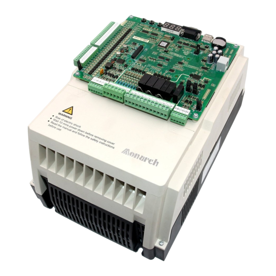
IP level IP20 Pollution degree Environment Power distribution TN, TT system 2.5 Physical Appearance and Mounting Dimensions The following figures show the physical appearance and mounting dimensions of the NICE3000 Figure 2-4 Physical appearance of the NICE3000 efesotomasyon.com - 27 -... - Page 29 Product Information NICE3000 User Manual Figure 2-5 Mounting dimensions of the NICE3000 The NICE3000 has different sizes. The following table lists the mounting dimensions of models under these sizes. Table 2-3 Mounting dimensions of the NICE3000 Hole Gross Controller Model...
- Page 30 SIZE-H NICE-L-C-4132 NICE-L-C-4160 Note For the models of other higher power classes that are still not often applied onsite, the preceding table does not list the mounting dimensions. If you need such models, directly contact Monarch. efesotomasyon.com - 29 -...
-
Page 31: Optional Parts
Product Information NICE3000 User Manual 2.6 Optional Parts If any optional part in the following table is required, specify it in your order. Table 2-4 Optional parts of the NICE3000 Name Model Function Remark For details, see External It is provided for the NICE3000 MDBUN section 2.7 "Selection... -
Page 32: Selection Of Braking Components
30 kW and below have a built-in braking unit, and you only need to connect an external braking resistor between PB and + terminals. For models above 30 kW, you need to install a braking unit and a braking resistor externally. Table 2-5 Braking resistor selection for the NICE3000 models Power of Max. - Page 33 Product Information NICE3000 User Manual Power of Max. Min. Power of Controller Model Adaptable Resistor Resistance Braking Braking Unit Motor (kW) Resistor (W) NICE-L-C-4037 16.0 11000 MDBUN-60-T NICE-L-C-4045 14.0 13500 MDBUN-60-T NICE-L-C-4055 12.0 16500 MDBUN-90-T NICE-L-C-4075 16×2 13 x 2...
-
Page 34: Chapter 3 Mechanical And Electrical Installation
Mechanical and Electrical Installation efesotomasyon.com... -
Page 35: Nice3000 New Integrated Elevator Controller
& regulations and related IEC requirements. 3.1.2 Installation Clearance Requirements The clearance that needs to be reserved varies with the power class of the NICE3000 , as Figure 3-1 Clearance around the NICE3000... - Page 36 NICE3000 User Manual Mechanical and Electrical Installation Figure 3-2 Diagram of mounting holes Fastening Fastener torque 1.1 kW P 15 kW 2.5 Nm 4-M5x15 bolt With fixing 4-M5x15 screw washer 4-M5x15 washer 18.5 kW P 45 kW 3.5 Nm NICE3000...
- Page 37 Mechanical and Electrical Installation NICE3000 User Manual Figure 3-3 Terminal arrangement of the NICE3000 CN12 NICE3000 integrated elevator controller Description of Main Circuit Terminals Figure 3-4 Main circuit terminal arrangement POWER MOTOR efesotomasyon.com - 36 -...
- Page 38 NICE3000 User Manual Mechanical and Electrical Installation Figure 3-5 Wiring of the main circuit Three-phase power supply Safety contactor POWER MOTOR (For models of below 37 kW) Braking resistor Three-phase AC power supply Safety contactor POWER MOTOR (For models of 37 kW and above)
- Page 39 Mechanical and Electrical Installation NICE3000 User Manual Terminal Name Description Grounding terminal Must be grounded. Precautions about wiring of the main circuit terminals are as follows: 1. Select the braking resistor according to the recommended values in the braking resistor selection table.
- Page 40 NICE3000 User Manual Mechanical and Electrical Installation Description of Control Circuit Terminals Table 3-2 Description of control circuit terminals Mark Code Terminal Name Function Description Terminal Arrangement Input voltage range: 10–30 X1 to Optocoupler isolation Input current limit: 5 mA...
-
Page 41: Ctb Board (Mctc-Ctb)
3.2 CTB Board (MCTC-CTB) 3.2.1 Dimensions and Installation The car top board (MCTC-CTB) is the elevator car control board of the NICE3000 . It consists of 8 DI terminals, 1 AI terminal, and 9 relay output terminals (standard: 7). The efesotomasyon.com... - Page 42 NICE3000 User Manual Mechanical and Electrical Installation Figure 3-6 Appearance and structure of the CTB D2 D1 C3 C2 C1 CN10 RESET MCTC-CTB X1 X2 X3 X4 X5 X6 X7 X8 Unit: mm Figure 3-7 Installation method of the CTB (unit: mm)
- Page 43 Mechanical and Electrical Installation NICE3000 User Manual Terminal Mark Terminal Name Function Description Arrangement Ai-M Load cell signal input 0–10 VDC 24 VDC power DI common terminal supply Light curtain 1 Light curtain 2 DI terminal Door open limit 1 1.
-
Page 44: Display Board (Mctc-Hcb)
NICE3000 User Manual Mechanical and Electrical Installation Terminal Mark Terminal Name Function Description Arrangement Connecting the external CN10 RJ45 interface operation panel CN10 Setting the CTB addresses: Short OFF or do not connect the terminal for a single CTB address jumper elevator. - Page 45 NICE3000 User Manual Monarch provides many types of display boards. The following part describes only a few common types. If the types available cannot meet your requirements, you can use a parallel-serial conversion board to make the board provided match your own. For any further requirement, contact Monarch.
- Page 46 NICE3000 User Manual Mechanical and Electrical Installation Figure 3-9 Installation method of HCB-H Plastic support higher Self-tapping than 1 cm screw 4- 4.9x30 Dot-matrix display board HCB-H 22.5 The following table describes the input and output terminals of HCB-H. Table 3-6 Input and output terminals of HCB-H...
- Page 47 Mechanical and Electrical Installation NICE3000 User Manual Terminal Function Terminal Wiring Name Down call indicator Interface for the down call button and indicator Down call Pins 2 and 3 are for down call input. button Pins 1 and 4 are power supply for the down call indicator (24 VDC output, load capacity: 40 mA).
- Page 48 NICE3000 User Manual Mechanical and Electrical Installation Figure 3-11 Installation method of HCB-R1 Self-tapping Plastic support screw higher than 1 cm 4- 4.9x30 Ultrathin dot- matrix display board HCB-R1 The following table describes the input and output terminals. Table 3-7 Input and output terminals of HCB-R1...
- Page 49 Mechanical and Electrical Installation NICE3000 User Manual 3.3.3 HCB-D2 (Ultrathin Segment LCD Display Board) Figure 3-12 Appearance and dimensions of HCB-D2 4- 3.5 56.0 UP DOWN ST XF Unit: mm 70.0 Figure 3-13 Installation method of HCB-D2 Plastic support Self-tapping...
- Page 50 NICE3000 User Manual Mechanical and Electrical Installation Table 3-8 Input and output terminals of HCB-D2 Terminal Function Terminal Wiring Name Up call indicator Interface for the up call button and indicator Up call Pins 2 and 3 are for up call input.
- Page 51 Mechanical and Electrical Installation NICE3000 User Manual 3.3.4 HCB-U1 (4.3-inch Segment LCD Display Board) Figure 3-14 Appearance and dimensions of HCB-U1 3-5.5 53.0 60.0 Unit: mm 79.2 Figure 3-15 Installation method of HCB-U1 Self-tapping Plastic support screw higher than 1 cm 4- 4.9x30...
- Page 52 NICE3000 User Manual Mechanical and Electrical Installation Table 3-9 Input and output terminals of HCB-U1 Terminal Function Terminal Wiring Name Up call indicator Interface for the up call button and indicator Pins 2 and 3 are for up call input.
- Page 53 Mechanical and Electrical Installation NICE3000 User Manual 3.3.5 HCB-V1 (6.4-inch Segment LCD Display Board) Figure 3-16 Appearance and dimensions of HCB-V1 Unit: mm Figure 3-17 Installation method of HCB-V1 Plastic support higher than 1 cm Self-tapping screw 4- 4.9x30 HCB-V1 14.2...
-
Page 54: Ccb Board (Mctc-Ccb)
NICE3000 User Manual Mechanical and Electrical Installation The following table describes the input and output terminals of HCB-V1. Table 3-10 Input and output terminals of HCB-V1 Terminal Name Function Terminal Wiring Up call indicator Interface for the up call button and indicator Pins 2 and 3 are for up call input. - Page 55 Mechanical and Electrical Installation NICE3000 User Manual Figure 3-18 Appearance and dimensions of the CCB 79 mm 69 mm Buzzer MCTC-CCB 1 2 3 4 1 2 3 4 1 2 3 4 1 2 3 4 Floor 1 Floor 2...
- Page 56 NICE3000 User Manual Mechanical and Electrical Installation The following table describes the input and output terminals of MCTC-CCB. Table 3-11 Input and output terminals of MCTC-CCB Interface Pins 2 and 3 Pins 1 and 4 Remarks Floor 1 button input...
-
Page 57: Selection And Use Of The Mctc
3.5.1 Selection of the MCTC-PG Card Monarch provides four PG card models, MCTC-PG-A2, MCTC-PG-D, MCTC-PG-E and MCTC-PG-F1 for different encoder types, as described in the following table. Table 3-12 Selection of the MCTC-PG card models Encoder Type... - Page 58 NICE3000 User Manual Mechanical and Electrical Installation Encoder Type Adaptable PG Card Appearance MCTC-PG-E SIN/COS encoder MCTC-PG-E Absolute encoder MCTC-PG-F1 MCTC-PG-F1 (ECN413/1313) 3.5.2 Terminal Wiring and Description of the MCTC-PG Card The MCTC-PG card is connected to the controller and the encoder as follows: The J1 terminal and CN1 terminal of the MCTC-PG card are respectively connected to the J12 terminal of the MCB on the controller and the encoder of the motor.
- Page 59 1. In general elevator applications, the input mains voltage is 380 V, and the motor voltage can only be equal to or smaller than 380 V. Thus, when selecting the NICE3000 , you can take only the current of the motor into consideration.
-
Page 60: Selection Of Peripheral Electrical Devices
NICE3000 User Manual Mechanical and Electrical Installation 3.6 Selection of Peripheral Electrical Devices 3.6.1 Description of Peripheral Electrical Devices 1. Do not install the capacitor or surge suppressor on the output side of the controller. Otherwise, it may cause faults to the controller or damage to the capacitor and surge suppressor. - Page 61 Mechanical and Electrical Installation NICE3000 User Manual MCCB Contactor Cable of Main Cable of Control Grounding Controller Model Circuit (mm²) Circuit (mm²) Cable (mm²) 220-NICE-L-C-4011 0.75 220-NICE-L-C-4015 0.75 220-NICE-L-C-4018 0.75 220-NICE-L-C-4022 0.75 220-NICE-L-C-4030 0.75 Three-phase 220 V, range: -15% to 20%, 50/60 Hz NICE-L-C-2002 0.75...
-
Page 62: Electrical Wiring Diagram Of The Nice3000
User Manual Mechanical and Electrical Installation 3.7 Electrical Wiring Diagram of the NICE3000 Control System Figure 3-22 Electrical wiring diagram of the NICE3000 control system See the last page of this chapter. 3.8 Installation of Shaft Position Signals In elevator control, to implement landing accurately and running safely, the car position... - Page 63 It is used to enable the car to land at each floor accurately. The leveling switches are generally installed on the top of the car. The NICE3000 system rail in the shaft. A leveling plate needs to be installed at each floor. Ensure that leveling...
- Page 64 Monarch. 3.8.2 Installation of Slow-Down Switches The slow-down switch is one of the key protective components of the NICE3000 protecting the elevator from over travel top terminal or over travel bottom terminal at maximum speed when the elevator position becomes abnormal.
- Page 65 Mechanical and Electrical Installation NICE3000 User Manual speed), and "F3-08" indicates the special deceleration rate. The default value of F3-08 (Special deceleration rate) is 0.9 m/s . The slow-down distances calculated based on different rated elevator speeds are listed in the following table:...
- Page 66 NICE3000 User Manual Mechanical and Electrical Installation 3.8.4 Installation of Final Limit Switches elevator does not stop completely upon passing the up/down limit switch. from the top leveling position. away from the bottom leveling position. efesotomasyon.com - 65 -...
- Page 68 Mechanical and Electrical Installation NICE3000 User Manual efesotomasyon.com - 66 -...
-
Page 69: Chapter 4 Use Of The Commissioning Tools
Use of the Commissioning Tools efesotomasyon.com... -
Page 70: Use Of The Onboard Keypad
Use of the Commissioning Tools NICE3000 User Manual Chapter 4 Use of the Commissioning Tools The NICE3000 supports three commissioning tools, 3-button keypad on the MCB, LED operation panel, and host computer monitoring software. Tool Function Description Remark It is used to enter the shaft commissioning... - Page 71 NICE3000 User Manual Use of the Commissioning Tools function code group menu, you can input simple references by using the UP button. SET: In the function code group menu, press this button to enter the menu of the function code group.
- Page 72 Use of the Commissioning Tools NICE3000 User Manual 5. F4: contract number display After you enter the F4 menu, the 7-segment LEDs display the user’s contract number. 6. F5: running times display After you enter the F5 menu, the 7-segment LEDs display the elevator running times circularly.
-
Page 73: Use Of The Led Operation Panel
NICE3000 User Manual Use of the Commissioning Tools You can press the PRG button to exit the auto-tuning state. 12. Fb: CTB state display After you enter the Fb menu, the 7-segment LEDs display the input/output state of the CTB. The following table describes the meaning of each segment of the LEDs. - Page 74 Use of the Commissioning Tools NICE3000 User Manual Figure 4-3 Diagram of the LED operation panel Function indicator LOCAL/REMOT FED/REV TUNE/TC Data display Unit indicator Increment key Programming Confirm key ENTER Shift key Menu key QUICK Decrement STOP RUN key MF.K...
- Page 75 NICE3000 User Manual Use of the Commissioning Tools 4.2.2 Description of Keys on the Operation Panel Table 4-2 Description of keys on the operation panel Name Function Programming Enter or exit Level-I menu. ENTER parameter setting. Increment Increase data or function code.
- Page 76 Use of the Commissioning Tools NICE3000 User Manual You can return to Level II menu from Level III menu by pressing . The ENTER difference between the two is as follows: After you press ENTER to Level II menu and shifts to the next function code.
- Page 77 NICE3000 User Manual Use of the Commissioning Tools Figure 4-6 Shift between parameters displayed in the stop state Shift between parameters displayed in the stop state In the running state, a total of 16 parameters can be displayed circularly by pressing .
- Page 78 Use of the Commissioning Tools NICE3000 User Manual efesotomasyon.com - 76 -...
-
Page 79: Chapter 5 System Commissioning And Application Example
System Commissioning and Application Example efesotomasyon.com... - Page 80 System Commissioning and Application Example NICE3000 User Manual Chapter 5 System Commissioning and Application Example 5.1 System Commissioning CAUTION Ensure that there is no person in the shaft or car before performing commissioning on the elevator. Ensure that the peripheral circuit and mechanical installation are ready before performing commissioning.
- Page 81 NICE3000 User Manual System Commissioning and Application Example Before power-on, check the peripheral wiring to ensure component and personal safety. The items to be checked include: Whether the component models are matched Whether the safety circuit is conducted and reliable...
- Page 82 Check the grounding terminals of all elevator electrical components and the power supply of the control cabinet 5.1.2 Setting and Auto-tuning of Motor Parameters The NICE3000 supports two major control modes, sensorless vector control (SVC) and closed-loop vector control (CLVC). SVC is applicable to inspection speed running for commissioning and fault judgment running during maintenance of the asynchronous motor.
- Page 83 NICE3000 User Manual System Commissioning and Application Example Function Code Parameter Name Description 0: Operation panel control F0-01 Command source selection 1: Distance control 0: No operation 1: With-load auto-tuning F1-11 Auto-tuning mode 2: No-load auto-tuning 3: Shaft auto-tuning Precautions for Motor Auto-tuning...
- Page 84 Motor auto-tuning is completed. motor starts to run. same. More descriptions of motor auto-tuning are as follows: When the NICE3000 drives the synchronous motor, an encoder is required to provide feedback signals. You must set the encoder parameters correctly before performing motor auto-tuning.
- Page 85 NICE3000 User Manual System Commissioning and Application Example Table 5-2 Output state of the RUN and brake contactors With-load Auto-tuning Operation Control mode No-load Auto- Distance Panel (F1-11 = 1) tuning Control Control Synchronous Asynchronous (F0-01 = 1) (F1-11 = 2)
- Page 86 System Commissioning and Application Example NICE3000 User Manual the CTB, and observe whether the door machine can open and close correspondingly. If the door machine cannot act properly, check whether BM/B1 and BM/B2 are wrongly connected to the input terminals of the door machine controller and whether commissioning of the door machine controller is complete.
- Page 87 NICE3000 User Manual System Commissioning and Application Example 5.1.5 Riding Comfort The riding comfort is an important factor of the elevator's overall performance. Improper installation of mechanical parts and improper parameter settings will cause discomfort. Enhancing the riding comfort mainly involves adjustment of the controller output and the elevator's mechanical construction.
- Page 88 System Commissioning and Application Example NICE3000 User Manual The optimum values of these two parameters are obtained during motor auto-tuning, and you need not modify them. Appropriate setting of the parameters can restrain jitter during running and have obvious effect on the riding comfort.
- Page 89 NICE3000 User Manual System Commissioning and Application Example F3-20 (Zero-speed control time at end) specifies the zero-speed output time when the running curve ends. brake apply command to the moment when the brake is completely applied, during which the system retains the zero-speed torque current output.
- Page 90 System Commissioning and Application Example NICE3000 User Manual Motor driving state: full-load up, no-load down Motor braking state: full-load down, no-load up of the car load to the rated load when the car and counterweight are balanced. when the motor runs at the drive or brake side. If the gain set is higher, then the calculated value of startup pro-torque compensation is higher.
-
Page 91: System Application
NICE3000 User Manual System Commissioning and Application Example 5.1.6 Password Setting The NICE3000 provides the parameter password protection function. Here gives an example of changing the password into 12345 ( indicates the blinking digit), as shown in Figure 5-5 Example of changing the password... - Page 92 System Commissioning and Application Example NICE3000 User Manual The three modes are described in detailed in the following part. Emergency 220 V UPS In this scheme, the 220 V UPS provides power supply to the main unit and the drive control...
- Page 93 NICE3000 User Manual System Commissioning and Application Example The following table lists the setting of the related parameters. Table 5-5 Parameter setting under the 220 V UPS scheme Function Code Parameter Name Setting Range Emergency evacuation switching F6-48 0.010–0.630 m/s...
- Page 94 Select the ARD with the nominal output power equal to or larger than the rated motor power. Monarch 380V ARD outputs the single-phase emergency voltage between the R and T phases to the control cabinet. Note that for ARDs of other brands, the phases that output the emergency voltage may be different.
- Page 95 NICE3000 User Manual System Commissioning and Application Example Figure 5-10 Wiring of the independent shorting PMSM stator contactor Braking resistor Safety contactor + – PB Motor Three-phase AC power supply NICE3000 Encoder MCTC-PG Shield Safety circuit 110 VAC FX: Shorting PMSM stator contactor SW: RUN contactor The parameter setting in such wiring mode is described in the following table.
- Page 96 System Commissioning and Application Example NICE3000 User Manual Function Binary Setting Remarks Description When it is set that the torque direction is Startup Startup torque compensation valid in automatically Bit4 compensation emergency evacuation running calculated, enable automatic startup torque compensation.
- Page 97 NICE3000 and NICE5000. This section describes the use of two elevators in parallel control. For use of multiple elevators in group control, refer to the description of the group control board or contact Monarch. Communication Ports for Parallel Control The following table lists the parameter setting of parallel control.
- Page 98 System Commissioning and Application Example NICE3000 User Manual Figure 5-11 Wiring when CAN1 is used for parallel control Elevator Elevator NICE3000 NICE3000 CAN1 cables for parallel control Elevator Elevator CAN+ CAN+ MCTC-CTB MCTC-CTB CAN- CAN- Up button indicator MOD+ MOD+...
- Page 99 NICE3000 User Manual System Commissioning and Application Example Address Setting of Physical Floors elevators are consistent. When two elevators are in parallel mode, the addresses of the HCBs should be set according to physical floors. Parallel running can be implemented only when the HCB...
- Page 100 4, which are implemented by using two methods set in Bit15 of FE-33. Method A: Same as that of NICE3000 Method B: New method, completely different from that of NICE3000 1. Control modes and related parameter setting. Table 5-12 Opposite door control modes and parameter setting...
- Page 101 NICE3000 User Manual System Commissioning and Application Example Opposite Door Control Parameter Setting Function Description Use Method Mode Method B FE-33 Bit15 = 0 (default) FC-04 = 0 The front door and back door act Mode 1 (Simultaneous simultaneously upon arrival for control) hall calls and car calls.
- Page 102 System Commissioning and Application Example NICE3000 User Manual Figure 5-14 CCB wiring for modes 1, 2, and 3 (dual operation boxes) MCTC-CTB-A Control Back door control Front door Back door Front door operation box Front door control Control Back door...
- Page 103 Set F8-16 = N, N > Number of floors 5.2.4 VIP Function Description The NICE3000 floor and provides services for special persons. After the system enters the VIP state, current car calls and halls are cleared; door open or close needs to be controlled manually;...
- Page 104 System Commissioning and Application Example NICE3000 User Manual Table 5-13 Parameter setting of the VIP function Function Parameter Setting Range Value Remarks Code Name They are used to set the top F6-00 F6-01 to 40 the elevator elevator, determined by the...
-
Page 105: Chapter 6 Function Code Table
Function Code Table efesotomasyon.com... -
Page 106: Function Code Description
Function Code Table NICE3000 User Manual Chapter 6 Function Code Table 6.1 Function Code Description 1. There are a total of 18 function code groups, each of which includes several function codes. The function codes adopt the three-level menu. The function code group number is Level-I menu;... - Page 107 NICE3000 User Manual Function Code Table Basic parameters Time parameters Motor parameters Keypad setting parameters Vector control parameters Door function parameters Running control parameters Protection function parameters Floor parameters Communication parameters Terminal function parameters Elevator function parameters Basic elevator parameters...
- Page 108 Function Code Table NICE3000 User Manual Function Parameter Name Setting Range Default Unit Property Code Model F1-03 Rated motor current 0.00–655.00 dependent Model F1-04 Rated motor frequency 0.00–99.00 dependent Rated motor rotational Model F1-05 0–3000 speed dependent Encoder initial angle...
- Page 109 NICE3000 User Manual Function Code Table Function Parameter Name Setting Range Default Unit Property Code Group F2: Vector control parameters Speed loop F2-00 0–100 proportional gain KP1 Speed loop integral F2-01 0.01–10.00 0.60 time TI1 Switchover frequency F2-02 0.00 to F2-05 2.00...
- Page 110 Function Code Table NICE3000 User Manual Function Parameter Name Setting Range Default Unit Property Code Deceleration end jerk F3-06 0.300–4.000 2.500 time Deceleration start jerk F3-07 0.300–4.000 2.500 time Special deceleration F3-08 0.200–1.500 0.900 rate Pre-deceleration F3-09 0–90.0 distance F3-10 Re-leveling speed 0.000–0.080...
- Page 111 NICE3000 User Manual Function Code Table Function Parameter Name Setting Range Default Unit Property Code Length 1 of leveling F4-04 0–65535 Pulses plate Length 2 of leveling F4-05 0–65535 Pulses plate F4-06 0–65535 Pulses height 1 F4-07 0–65535 Pulses F4-08 0–65535...
- Page 112 Function Code Table NICE3000 User Manual Function Parameter Name Setting Range Default Unit Property Code F4-25 0–65535 Pulses F4-80 0–65535 Pulses height 38 F4-81 0–65535 Pulses F4-82 0–65535 Pulses height 39 F4-83 0–65535 Pulses Group F5: Terminal function parameters Attendant/Automatic F5-00 3–200...
- Page 113 NICE3000 User Manual Function Code Table Function Parameter Name Setting Range Default Unit Property Code 22/54: Shorting door F5-09 X9 function selection lock circuit contactor feedback F5-10 X10 function selection signal 24/56: Door machine 1 light curtain signal F5-11 X11 function selection...
- Page 114 Function Code Table NICE3000 User Manual Function Parameter Name Setting Range Default Unit Property Code 0: Invalid 1: RUN contactor control F5-26 Y1 function selection 2: Brake contactor control 3: Shorting door lock circuit contactor control arrival signal feedback F5-27...
- Page 115 NICE3000 User Manual Function Code Table Function Parameter Name Setting Range Default Unit Property Code emergency requirement for Hong Kong Bit4: Arrival gong disabled at night Bit6: Door lock disconnected at inspection switched over to normal running Terminal program F5-33...
- Page 116 Function Code Table NICE3000 User Manual Function Parameter Name Setting Range Default Unit Property Code Number of elevators in F6-07 1–8 parallel/group mode F6-08 Elevator No. 1–8 Bit0: Dispersed waiting Bit3: Parallel/Group control implemented at CAN2 Bit4: Group control in compatibility with...
- Page 117 NICE3000 User Manual Function Code Table Function Parameter Name Setting Range Default Unit Property Code Bit1: Disabling returning Bit2: Cancelling auto sequential arrange of to be displayed Bit5: Current detection valid at startup for synchronous motor Bit6: Reversing MCB lamp output...
- Page 118 Function Code Table NICE3000 User Manual Function Parameter Name Setting Range Default Unit Property Code F6-20 0–65535 65535 F6-21 0–65535 65535 Start time of time- F6-22 00.00–23.59 00.00 HH.MM End time of time-based F6-23 00.00–23.59 00.00 HH.MM F6-24 0–65535 65535 F6-25 0–65535...
- Page 119 NICE3000 User Manual Function Code Table Function Parameter Name Setting Range Default Unit Property Code Bit0: Disability function Bit1: Soft limit function Bit2: JP16 input used as back door selection Bit3: JP16 input used as the back door open signal...
- Page 120 Function Code Table NICE3000 User Manual Function Parameter Name Setting Range Default Unit Property Code Bit2: Inspection to stop due to slow-down 1 Bit4: Buzzer tweet during door open delay Bit6: Cancelling door open delay Bit8: Elevator lock at door open...
- Page 121 NICE3000 User Manual Function Code Table Function Parameter Name Setting Range Default Unit Property Code Bit0: Calls cancelled after entering attendant state Bit1: Not responding to hall calls Bit2: Attendant/ Automatic state switchover Bit3: Door close at jogging Attendant function...
- Page 122 Function Code Table NICE3000 User Manual Function Parameter Name Setting Range Default Unit Property Code Bit3: Arrival gong output emergency state Bit4: Multiple car emergency state Bit5: Retentive at power state Bit6: Closing door by holding down the door close button...
- Page 123 NICE3000 User Manual Function Code Table Function Parameter Name Setting Range Default Unit Property Code Bit0-Bit1: Direction determine mode (00: Automatically calculating direction; 01: Load direction determining; 10: Direction of nearest Bit2: Stopping at Bit3: Reserved Bit4: Compensation at startup...
- Page 124 Function Code Table NICE3000 User Manual Function Parameter Name Setting Range Default Unit Property Code F7-02 0 to F6-00 registered F7-03 Random running times 0–60000 0: Yes F7-04 Hall call enabled 1: No 0: Yes F7-05 Door open enabled 1: No...
- Page 125 NICE3000 User Manual Function Code Table Function Parameter Name Setting Range Default Unit Property Code 0: Motor not running Emergency evacuation 1: UPS F8-10 operation mode at 2: 48 V battery power power failure supply F8-11 Brake apply delay 0.200–1.500 0.200...
- Page 126 Function Code Table NICE3000 User Manual Function Parameter Name Setting Range Default Unit Property Code Group FA: Keypad setting parameters 0: Reversed display of 1: Positive display of Keypad display FA-00 selection 2: Reversed display of 3: Positive display of hall...
- Page 127 NICE3000 User Manual Function Code Table Function Parameter Name Setting Range Default Unit Property Code FA-27 Input state 2 0–65535 FA-28 Input state 3 0–65535 FA-30 Input state 5 0–65535 FA-31 Output state 1 0–65535 FA-32 Output state 2 0–65535...
- Page 128 Function Code Table NICE3000 User Manual Function Parameter Name Setting Range Default Unit Property Code 0: Closing the door as Door state of standby 1: Waiting with door Fb-10 elevator 2: Waiting with door Door open holding Fb-11 1–1000 time for hall call...
- Page 129 NICE3000 User Manual Function Code Table Function Parameter Name Setting Range Default Unit Property Code Bit0: Overload protection Bit1: Canceling protection at output phase loss Bit2: Canceling over- modulation function Program control 2 for Bit4: Light curtain FC-01 protection function...
- Page 130 Function Code Table NICE3000 User Manual Function Parameter Name Setting Range Default Unit Property Code Output frequency upon FC-18 0.00–99.99 designated fault Torque current upon FC-19 0.0–999.9 designated fault FC-20 1st fault code 0–9999 FC-21 1st fault subcode 0–65535 1st fault month and FC-22 0–1231...
- Page 131 NICE3000 User Manual Function Code Table Function Parameter Name Setting Range Default Unit Property Code Latest fault hour and FC-63 0–23.59 HH.MM minute Logic information of FC-64 0–65535 latest fault Curve information of FC-65 0–65535 latest fault Set speed upon latest FC-66 0.000–4.000...
- Page 132 Function Code Table NICE3000 User Manual Function Parameter Name Setting Range Default Unit Property Code 0: Reserved NO/NC input: Fd-07 HCB:JP1 input 1/33: Elevator lock signal 2/34: Fire emergency signal forbidden signal Fd-08 HCB:JP2 input 6/38: Door close button input signal...
- Page 133 NICE3000 User Manual Function Code Table Function Parameter Name Setting Range Default Unit Property Code Fd-17 HCB-B:A1 output 0: Reserved Fd-18 HCB-B:A2 output 1: Fault output Fd-19 HCB-B:B1 output 2: Non-door zone stop output Fd-20 HCB-B:B2 output 3: Non-service state...
- Page 134 Function Code Table NICE3000 User Manual Function Parameter Name Setting Range Default Unit Property Code FE-07 Floor 7 display 17: Display "R" 1907 18: Display "-" FE-08 Floor 8 display 1908 19: No display FE-09 Floor 9 display 1909 20: Display "12"...
- Page 135 NICE3000 User Manual Function Code Table Function Parameter Name Setting Range Default Unit Property Code Bit2: Re-leveling function Bit3: Door pre-open function Bit4: Stuck hall call cancellation function Bit6: Down collective Elevator function selective peak service FE-32 34816 selection 1...
- Page 136 Function Code Table NICE3000 User Manual Function Parameter Name Setting Range Default Unit Property Code Group Fr: Leveling adjustment parameters 0: Disabled Leveling adjustment Fr-00 function 1: Enabled Leveling adjustment Fr-01 30030 record 1 Leveling adjustment Fr-02 30030 record 2 00000–60060...
-
Page 137: Chapter 7 Description Of Function Codes
Description of Function Codes efesotomasyon.com... -
Page 138: Group F0: Basic Parameters
Description of Function Codes NICE3000 User Manual Chapter 7 Description of Function Codes Group F0: Basic Parameters Function Parameter Setting Range Default Unit Property Code Name 0: Sensorless vector control (SVC) Control 1: Closed-loop vector control F0-00 mode (CLVC) 2: Voltage/Frequency (V/F) control It is used to set the control mode of the system. - Page 139 NICE3000 User Manual Description of Function Codes Function Code Parameter Name Setting Range Default Unit Property Running speed under F0-02 0.050 to F0-04 0.050 operation panel control It is used to set the running speed in the operation panel control mode.
-
Page 140: Group F1: Motor Parameter
Description of Function Codes NICE3000 User Manual If the carrier frequency is high, power loss and temperature rise of the motor declines. However, the system has an increase in power loss, temperature rise and interference. table. Carrier frequency High Motor noise... - Page 141 NICE3000 User Manual Description of Function Codes Function Parameter Name Setting Range Default Unit Property Code Rated motor Model F1-04 0.00–99.00 frequency dependent Rated motor rotational Model F1-05 0–3000 speed dependent Set these parameters according to the motor nameplate. Ensure that these motor parameters are set correctly. Incorrect setting affects the motor auto-tuning and the vector control effect.
- Page 142 Description of Function Codes NICE3000 User Manual Function Code Parameter Name Setting Range Default Unit Property 0: No operation 1: With-load auto-tuning F1-11 Auto-tuning mode 2: No-load auto-tuning 3: Shaft auto-tuning It is used to select the auto-tuning mode. "With-load auto-tuning" is static auto-tuning for the asynchronous motor and rotary auto- tuning for the synchronous motor.
-
Page 143: Group F2: Vector Control Parameters
NICE3000 User Manual Description of Function Codes Function Code Parameter Name Setting Range Default Unit Property Mutual inductance Model F1-17 0.1–3000.0 (asynchronous motor) dependent Magnetizing current Model F1-18 0.01–300.00 (asynchronous motor) dependent These parameters are obtained by means of motor auto-tuning. After the motor auto-tuning is completed successfully, the values of these parameters are updated automatically. - Page 144 Description of Function Codes NICE3000 User Manual Figure 7-1 Relationship between running frequencies and PI parameters parameters F2-00 F2-01 F2-03 F2-04 Frequency F2-02 (Switchover F2-05 (Switchover reference (Hz) frequency 1) frequency 2) The speed dynamic response characteristics in vector control can be adjusted by setting the proportional gain and integral time of the speed regulator.
-
Page 145: Group F3: Running Control Parameters
NICE3000 User Manual Description of Function Codes You can modify this parameter to reverse the running direction (without changing the wiring of the motor). check whether the actual motor running direction is consistent with the inspection command direction. If not, change the motor running direction by setting F2-10 to consistent with the inspection command direction. - Page 146 Description of Function Codes NICE3000 User Manual Function Code Parameter Name Setting Range Default Unit Property F3-02 Acceleration rate 0.200–1.500 0.600 F3-03 Acceleration start jerk time 0.300–4.000 2.500 F3-04 Acceleration end jerk time 0.300–4.000 2.500 These parameters are used to set the running curve during acceleration of the elevator.
- Page 147 For the installation positions of the slow-down switches, see the description of section 3.8.2. The NICE3000 integrated elevator controller supports a maximum of three pairs of slow- down switches. From two sides of the shaft to the middle, slow-down 1, slow-down 2, and There may be only one pair of slow-sown switches for the low-speed elevator, and two or three pairs of slow-down switches for the high-speed elevator.
- Page 148 Description of Function Codes NICE3000 User Manual the brake release command to the moment when the brake is completely released, during which the system retains the zero-speed torque current output. running curve ends. brake apply command to the moment when the brake is completely applied, during which the system retains the zero-speed torque current output.
-
Page 149: Group F4: Floor Parameters
These two parameters indicate the absolute pulses of the current position of the elevator car relative to the bottom leveling position. The position data of the NICE3000 in the shaft is recorded in pulses. Each position is expressed by a 32-bit binary number, where the high 16 bits indicate the high byte of the... -
Page 150: Group F5: Terminal Function Parameters
01: Up leveling signal 02: Down leveling signal 03: Door zone signal The NICE3000 system determines the elevator leveling position based on the leveling sensor, up and down leveling sensors, and door zone sensor plus the up/down leveling sensor. - Page 151 NICE3000 User Manual Description of Function Codes The following table describes the sequence of received signals for the three types of leveling Signal Receiving Sequence Up leveling Down leveling Door zone Up direction Down direction sensor sensor sensor Door zone signal...
- Page 152 Description of Function Codes NICE3000 User Manual 14: Overload signal When the elevator load exceeds 110% of the rated load during normal use, the elevator enters the overload state. Then the overload buzzer beeps, the overload indicator in the car becomes ON, and the elevator door keeps open. The overload signal becomes invalid when the door lock is applied.
- Page 153 It is used for allocation of elevators in parallel or group mode and judgment of the emergency running direction at power failure. 76: Door 1 open input 77: Door 2 open input The NICE3000 Function Code Parameter Name Setting Range...
- Page 154 Description of Function Codes NICE3000 User Manual Parameter Name Default Parameter Name Default Bit0 Door machine 1 light curtain Bit5 Door machine 2 close limit Bit1 Door machine 2 light curtain Bit6 Full-load signal (digital) Bit2 Door machine 1 open limit...
- Page 155 NICE3000 User Manual Description of Function Codes 13: Emergency evacuation automatic switchover When detecting that the bus voltage declines to a certain value after power failure occurs on the mains supply, the controller outputs this signal and uses the battery for temporary power supply, implementing emergency evacuation running.
- Page 156 Description of Function Codes NICE3000 User Manual Figure 7-4 Communication state monitoring Monitoring CANbus Monitoring Modbus communication status communication status between the HOPs at all floors and the MCB between the CTB and the MCB Corresponding Normal Modbus Meaning of Segment ON...
- Page 157 NICE3000 User Manual Description of Function Codes Figure 7-5 Example of LED display indicating the communication state Function Code Parameter Name Setting Range Default Unit Property F5-33 Terminal program control 0–65535 It is used to set the elevator functions. Whether a function is enabled is indicated by a binary bit: "1"...
- Page 158 Description of Function Codes NICE3000 User Manual Figure 7-6 Monitoring of all I/O terminals F5-34 F5-35 Segment Indication No. Segment Indication Light curtain 1 Up leveling signal Light curtain 2 Down leveling signal Door 1 open limit Door zone signal...
- Page 159 NICE3000 User Manual Description of Function Codes F5-34 F5-35 Segment Indication No. Segment Indication Door machine 1 light curtain Door open button display Door machine 2 light curtain Door close button display Brake contactor feedback 2 Door open delay button display...
-
Page 160: Group F6: Basic Elevator Parameters
Description of Function Codes NICE3000 User Manual Group F6: Basic Elevator Parameters Function Code Parameter Name Setting Range Default Unit Property F6-00 F6-01 to 40 F6-01 1 to F6-00 These two parameters are used to set the top floor and bottom floor of the elevator, determined by the number of actually installed leveling plates. - Page 161 NICE3000 User Manual Description of Function Codes Floor Whether Service Setting Floor Whether Service Setting Bit2 Floor 3 Allowed Bit10 Floor 11 Allowed Bit3 Floor 4 Allowed Bit11 Floor 12 Forbidden Bit4 Floor 5 Allowed Bit12 Floor 13 Allowed Bit5...
- Page 162 NICE3000 User Manual Function Description Default This function is used when the NICE3000 is Group control in involved in the group control system. The setting Bit4 compatibility with of this bit must be the same as that for all the NICE3000 other elevators in the group.
- Page 163 NICE3000 User Manual Description of Function Codes Function Description Default Reversing MCB After this function is enabled, the MCB lamp output logic Bit6 lamp output is reversed. Door open valid at In the inspection state, you can open/close the door by...
- Page 164 Description of Function Codes NICE3000 User Manual Function Code Parameter Name Setting Range Default Unit Property Start time of down F6-14 00.00–23.59 00.00 HH.MM collective selective 1 End time of down F6-15 00.00–23.59 00.00 HH.MM collective selective 1 Start time of down F6-16 00.00–23.59...
- Page 165 NICE3000 User Manual Description of Function Codes Function Code Parameter Name Setting Range Default Unit Property F6-26 Peak 1 start time 00.00–23.59 00.00 HH.MM F6-27 Peak 1 end time 00.00–23.59 00.00 HH.MM F6-28 F6-01 to F6-00 F6-29 Peak 2 start time 00.00–23.59...
- Page 166 Description of Function Codes NICE3000 User Manual F6-40 Program Control Selection 1 Function Description Default This function is enabled only in the opposite door control mode 2 (hall call independent, opposite-door manual control). In this case, only one door opens...
- Page 167 NICE3000 User Manual Description of Function Codes F6-41 Program Control Selection 2 Function Description Default Bit0 Reserved Bit1 Reserved Inspection to stop due During inspection running, if the slow-down 1 acts, the Bit2 to slow-down 1 system decelerates to stop.
- Page 168 Description of Function Codes NICE3000 User Manual Function Code Parameter Name Setting Range Default Unit Property F6-43 Attendant function selection 0–65535 It is used to select the attendant-related elevator functions. "1" indicates that the function is enabled, and "0" indicates that the function is disabled.
- Page 169 NICE3000 User Manual Description of Function Codes Table 7-10 Fire emergency functions indicated by bits of F6-44 F6-44 Fire Emergency Function Selection Function Description Default Bit0 to Reserved Bit2 Arrival gong output Bit3 emergency state. emergency state Multiple car calls Bit4 emergency state.
- Page 170 Description of Function Codes NICE3000 User Manual Function Code Parameter Name Setting Range Default Unit Property Emergency evacuation F6-45 0–65535 function selection It is used to select the emergency evacuation-related functions. "1" indicates that the function is enabled, and "0" indicates that the function is disabled.
- Page 171 NICE3000 User Manual Description of Function Codes F6-45 Emergency Evacuation Function Selection Function Description Default The system exits emergency evacuation when receiving the door open limit signal from the elevator Emergency Bit14 evacuation exit The system exits emergency evacuation when...
-
Page 172: Group F7: Test Function Parameters
0–60000 It is used to set the random running times of the system. The NICE3000 has the random automatic running function. If the setting of F7-03 is greater than 60000, the system keeps implementing random automatic running until you set F7-03 to 0. -
Page 173: Group F8: Enhanced Function Parameters
NICE3000 User Manual Description of Function Codes Function Code Parameter Name Setting Range Default Unit Property 0: Yes F7-05 Door open enabled 1: No It is used to enable the door open function. 0: Yes (door open allowed) 1: No (door open forbidden) - Page 174 Description of Function Codes NICE3000 User Manual 1. Ensure that F8-01 is set to 0 and F5-36 is set to 2 or 3 to make the system allow load cell auto tuning. ENTER 3. Put N% load in the car. Then set F8-00 to N and press the ENTER key.
- Page 175 Default Unit Property F8-05 Current car load 0–1023 the NICE3000 by using a load cell. This parameter is used to judge overload or full-load, or calculate the torque current for load cell pre-torque compensation. Function Code Parameter Name Setting Range...
-
Page 176: Group F9: Time Parameters
Description of Function Codes NICE3000 User Manual Function Code Parameter Name Setting Range Default Unit Property Emergency evacuation F8-10 0–2 operation mode at power failure It is used to set the emergency evacuation operation mode at power failure. 0: Motor not running... - Page 177 NICE3000 User Manual Description of Function Codes Function Code Parameter Name Setting Range Default Unit Property Time for fan and lamp F9-01 0–240 to be turned off It is used to set the time that fan and lamp stays ON before being turned off automatically.
-
Page 178: Group Fa: Keypad Setting Parameters
Default Unit Property FA-00 Keypad display selection 0–3 The NICE3000 system has three buttons and three 7-segment LEDs on the MCB. You can change the display content through the setting of this parameter. Function Code Parameter Name Setting Range Default... - Page 179 NICE3000 system, in unit of V. Output current: indicates the effective value of the actual current when the NICE3000 system drives the motor to turn, in unit of A. Output frequency: indicates the actual frequency of the motor during running. It has a Input terminal low bits: indicate the meaning of input terminals by bit.
- Page 180 Description of Function Codes NICE3000 User Manual Meaning Meaning Bit0 Reserved Bit8 Inspection signal Bit1 Up leveling signal Bit9 Inspection up signal Bit2 Down leveling signal Bit10 Inspection down signal Bit3 Door zone signal Bit11 Fire emergency signal Bit4 Safety circuit feedback 1...
- Page 181 NICE3000 User Manual Description of Function Codes 10) Current floor: indicates the information of the physical floor where the elevator is located. It is the same as the value of F4-01. 11) Current position: indicates the absolute distance from the current elevator car to the...
- Page 182 6: Attendant operation Bit7 Bit15 Reserved 7: Automatic (normal) 16) Pre-torque current: indicates the percentage of the pre-torque current compensated by the NICE3000 system at startup to the rated current, in unit of %. Function Code Parameter Name Setting Range Default...
- Page 183 NICE3000 User Manual Description of Function Codes Function Code Parameter Name Setting Range Default Unit Property FA-12 Logic information 0–65535 It displays the elevator status parameters. The LEDs are arranged as 5, 4, 3, 2, 1 from left to right. LED 1 shows the state of door 1.
- Page 184 Description of Function Codes NICE3000 User Manual LED 5 LED 4 LED 3 LED 2 LED 1 Curve Information Display Display Display Standby state Deceleration start segment Zero-speed start Linear deceleration segment segment Zero-speed holding Deceleration end segment segment Reserved...
- Page 185 NICE3000 User Manual Description of Function Codes Table 7-16 Communication quality display LED 5 LED 4 LED 3 LED 2 LED 1 CAN2 Modbus CAN1 Communication Communication Communication Communication Display Quality Quality Quality Quality Good Good Good Good Interrupted Interrupted...
- Page 186 Description of Function Codes NICE3000 User Manual FA-26 Input state 1 FA-28 Input state 3 Function Function Function Function Fire emergency Reserved Inspection signal Reserved switchover Door 1 safety Up leveling signal Inspection up Reserved edge signal Down leveling Door 2 safety...
- Page 187 NICE3000 User Manual Description of Function Codes FA-31 Output state 1 FA-32 Output state 2 Function Function Function Function Higher-voltage Reserved Door 2 close startup of Reserved brake Brake and RUN Elevator RUN contactor contactors running in up Reserved output...
- Page 188 Description of Function Codes NICE3000 User Manual FA-35 Hall state Function Function Function Function Reserved VIP signal Reserved Reserved Elevator lock signal Security signal Reserved Reserved Fire emergency Door close Reserved Reserved signal button input Reserved Reserved Reserved forbidden FA-36 System state 1...
-
Page 189: Group Fb: Door Function Parameter
NICE3000 User Manual Description of Function Codes Group Fb: Door Function Parameter Function Code Parameter Name Setting Range Default Unit Property Fb-00 Number of door machine (s) 1–2 It is used to set the number of door machine(s). Set this parameter based on actual conditions. - Page 190 Description of Function Codes NICE3000 User Manual Function Code Parameter Name Setting Range Default Unit Property Fb-08 Door close protection time 5–99 It is used to set the door close protection time. After outputting the door close command, if the system does not receive the door close limit signal after the time set in this parameter, the system re-closes the door.
-
Page 191: Group Fc: Protection Function Parameters
NICE3000 User Manual Description of Function Codes Function Code Parameter Name Setting Range Default Unit Property Fb-14 Door open delay 10–1000 It is used to set the door open holding time when there is door open delay input. The elevator closes the door immediately after receiving a door close command. - Page 192 Description of Function Codes NICE3000 User Manual FC-00 Program control for protection function Function Description Default In this mode, the door open/close limit signal is not required, and the system automatically judges door Mode without door open/close limit. The system determines that door...
- Page 193 NICE3000 User Manual Description of Function Codes Function Code Parameter Name Setting Range Default Unit Property FC-04 Opposite door selection 0–3 It is used to set opposite door-related control function. The values are as follows: 0: Simultaneous control 1: Hall call independent, car call simultaneous...
- Page 194 Description of Function Codes NICE3000 User Manual Function Code Parameter Name Setting Range Default Unit Property FC-20 1st fault code 0–9999 FC-21 1st fault subcode 0–65535 FC-22 1st fault month and day 0–1231 MM.DD FC-23 1st fault hour and minute 0–23.59...
-
Page 195: Group Fd: Communication Parameters
NICE3000 User Manual Description of Function Codes Group Fd: Communication Parameters Function Code Parameter Name Setting Range Default Unit Property 0: 9600 Fd-00 Baud rate bit/s 1: 38400 0–127 Fd-02 Local address 0: Broadcast address Communication Fd-03 0–20 response delay 0.0–60.0... - Page 196 Description of Function Codes NICE3000 User Manual Function Code Parameter Name Setting Range Default Unit Property 0: Invalid 1: Up arrival indicator Fd-09 HCB:JP1 output 2: Down arrival indicator 3: Fault output 4: Non-door zone stop output 5: Non-service state output...
-
Page 197: Group Fe: Elevator Function Parameters
NICE3000 User Manual Description of Function Codes These parameters are used to set the functions of four relay outputs and six open-collector outputs on the HCB-B no-display parallel-serial conversion board. The setting is effective to all HCB-Bs connected to the system. - Page 198 Description of Function Codes NICE3000 User Manual where the two high digits indicate the display code of the ten's digit, and the two low digits indicate the display code of the unit's digit. Function Code Parameter Name Setting Range Default...
- Page 199 NICE3000 User Manual Description of Function Codes FE-32 Elevator function selection 1 Function Description Default Down collective Bit6 selective peak The peak service at down collective selective is used. service Parallel/Group Bit7 control peak The peak service is used. service...
-
Page 200: Group Fr: Leveling Adjustment Parameters
Description of Function Codes NICE3000 User Manual FE-33 Elevator Function Selection 2 Function Description Default If the door still does not close within the time set in Fb-17 in automatic state, the system outputs the Bit7 Forced door close forced door close signal; at this moment, the light curtain becomes invalid and the buzzer tweets. - Page 201 NICE3000 User Manual Description of Function Codes Figure 7-9 Viewing the leveling adjustment record Each segment indicates a Function code State function code. leveling adjustment; if the value is smaller than 30, it is downward leveling adjustment. The default value "30" indicates that there is no leveling adjustment. The maximum adjustment range is ±30 mm.
-
Page 202: Group Ff: Factory Parameters
If FP-00 is set to 00000, the previously set user password is cleared, and the password protection function is disabled. Remember the password that you set. If the password is set incorrectly or forgotten, contact Monarch to replace the control board. Function Code Parameter Name... -
Page 203: Chapter 8 Troubleshooting
Troubleshooting efesotomasyon.com... -
Page 204: Maintenance
Troubleshooting NICE3000 User Manual Chapter 8 Troubleshooting 8.1 Maintenance 8.1.1 Routine Maintenance of the components inside the controller, which may cause potential faults or reduce the service life of the controller. Therefore, it is necessary to carry out routine and periodic maintenance. -
Page 205: Description Of Fault Levels
8.1.4 Storage of the Controller For storage of the controller, pay attention to the following two aspects: 1. Pack the controller with the original packing box provided by Monarch. 2. Long-term storage degrades the electrolytic capacitor. Thus, the controller must be energized once every 2 years, each time lasting at least 5 hours. - Page 206 Troubleshooting NICE3000 User Manual Table 8-2 Fault levels Category Action Remarks 1. Display the fault code. 1A. The elevator running is not affected on any Level 1 2. Output the fault relay action condition. command. 1. Display fault code. 2A. The paralle/group control l function is disabled.
-
Page 207: Fault Information And Troubleshooting
NICE3000 User Manual Troubleshooting 8.3 Fault Information and Troubleshooting If an alarm is reported, the system performs corresponding processing based on the fault level. You can handle the fault according to the possible causes described in the following table. Table 8-3 Fault codes and troubleshooting... - Page 208 Troubleshooting NICE3000 User Manual Fault Name Possible Causes Solution Level Code Check: Whether encoder pulses per revolution (PPR) is set correctly Whether the encoder signal is interfered with Whether the encoder cable runs through the duct independently Whether the cable is too long...
- Page 209 The elevator is not Disable the maintenance Err08 maintained within the period reached F9-13 to 0. Contact the agent or Monarch. Instantaneous power Eliminate external power failure occurs on the supply faults and check input power supply. whether the power fails during running.
- Page 210 If not, phase loss The drive control board adjust the power input. fails. Contact the agent or Monarch. Check the wiring. The output wiring of the Power output Check whether the contactor main circuit is loose.
- Page 211 Current The drive control board Err18 Contact the agent or Monarch. detection fault fails. Enter the motor parameters correctly. Check the motor wiring and whether phase loss occurs...
- Page 212 Troubleshooting NICE3000 User Manual Fault Name Possible Causes Solution Level Code 1: AB signals are lost during auto-tuning. 3: The phase sequence of the motor is incorrect. 4: Z signal cannot be detected during auto-tuning. 5: The CD signal cables of the SIN/COS encoder break.
- Page 213 NICE3000 User Manual Troubleshooting Fault Name Possible Causes Solution Level Code 101: 101: The RTC clock Err24 RTC clock fault information of the MCB is Replace the clock battery. abnormal. Replace the MCB. 101, 102: Storage data 101, 102: Contact the agent or...
- Page 214 Bit8 of F6-45), and the requirements. running time exceeds 50s, Check whether the emergency causing the timeout fault. running speed is set properly. Logic of the MCB is Err34 Logic fault Contact the agent or Monarch. abnormal. efesotomasyon.com - 212 -...
- Page 215 NICE3000 User Manual Troubleshooting Fault Name Possible Causes Solution Level Code 101: Check that the next slow- down switch is valid, and that F4- 102: Check that the inspection switch is in inspection state. 103, 104: 101: When shaft auto- tuning is started, the Perform shat auto-tuning.
- Page 216 Troubleshooting NICE3000 User Manual Fault Name Possible Causes Solution Level Code 101, 102, 104: 101: The feedback of the RUN contactor is active, but Check whether the feedback the contactor has no output. contact of the contactor acts properly. 102: The controller outputs...
- Page 217 Code Elevator The set elevator running Check the related parameter, or Err40 running time is reached. contact the agent or Monarch. reached 101: Check the safety circuit switches and their states. Check whether the external Safety circuit 101: The safety circuit power supply is normal.
- Page 218 Troubleshooting NICE3000 User Manual Fault Name Possible Causes Solution Level Code 101: The down slow-down 101 to 103: Check whether the up slow- during shaft auto-tuning. down 1 and the down slow- 102: The up slow-down down 1 are in good contact.
- Page 219 NICE3000 User Manual Troubleshooting Fault Name Possible Causes Solution Level Code 101: Check whether the door machine system works 101: The consecutive times properly. that the door does not open Err48 Door open fault to the limit reaches the Check whether the CTB is setting in Fb-13.
- Page 220 Troubleshooting NICE3000 User Manual Fault Name Possible Causes Solution Level Code 101: Check the communication cable connection. Check whether the 24 V power 101: Feedback data of supply of the controller is Modbus communication Err52 communication normal. with the HCB remains...
- Page 221 NICE3000 User Manual Troubleshooting Fault Name Possible Causes Solution Level Code 101, 102: 101: The up slow- Check whether the states down and down slow- (NO, NC) of the slow-down down are disconnected Shaft position switches and limit switches are simultaneously.
- Page 222 Troubleshooting NICE3000 User Manual efesotomasyon.com - 220 -...
-
Page 223: Chapter 9 Emc
efesotomasyon.com... -
Page 224: Introduction To Emc Standard
NICE3000 User Manual Chapter 9 EMC Electromagnetic compatibility (EMC) describes the ability of electronic and electrical devices or systems to work properly in the electromagnetic environment and not to In other words, EMC includes two aspects: The electromagnetic interference generated by a device or system must be restricted within a certain limit;... -
Page 225: Selection Of Peripheral Emc Devices
The NICE3000 installed on the power input side. The installation precautions are as follows: contact with the metal ground of the installation cabinet on a large area, and requires good conductive continuity. - Page 226 NICE3000 User Manual Power Rated Input AC Input Filter Model AC Input Filter Model Controller Model Capacity Current (A) (Changzhou Jianli) (Schaffner) (kVA) Three-phase 380 V, range: -15% to 20% NICE-L-C-4002 DL-10EBK5 FN 3258-7-44 NICE-L-C-4003 10.5 DL-16EBK5 FN 3258-16-33 NICE-L-C-4005 14.8...
- Page 227 NICE3000 User Manual 9.3.2 Installation of AC Input Reactor on Power Input Side An AC input reactor is installed to eliminate the harmonics of the input current. As an optional device, the reactor can be installed externally to meet strict requirements of an application environment for harmonics.
-
Page 228: Shielded Cable
NICE3000 User Manual Power Capacity Rated Input Current AC Input Reactor Model Controller Model (kVA) (Inovance) Single-phase 220 V, range: -15% to 20% NICE-L-C-2002 13.2 NICE-L-C-2003 17.0 220-NICE-L-C-4007 29.0 220-NICE-L-C-4011 12.1 36.0 Consult the manufacturer. 220-NICE-L-C-4015 13.9 41.0 220-NICE-L-C-4018 17.3 40.0... - Page 229 NICE3000 User Manual It is recommended that all control cables be shielded. The grounding area of the shielded plate using the metal cable clamp so as to achieve good contact, as shown in the following Shielded cable Metal plate Metal cable clamp...
-
Page 230: Solutions To Common Emc Interference Problems
NICE3000 User Manual 9.4.3 Cabling Requirement 1. The motor cables must be laid far away from other cables, with recommended distance larger than 0.5 m. The motor cables of several controllers can be laid side by side. 2. It is recommended that the motor cables, power input cables and control cables be laid in different ducts. - Page 231 NICE3000 User Manual Interference Type Solution Connect the motor housing to the PE of the controller. Connect the PE of the controller to the PE of the mains power supply. Leakage protection switch tripping Add a safety capacitor to the power input cable.
- Page 232 NICE3000 User Manual efesotomasyon.com - 230 -...
- Page 233 5. The Product Warranty Card is not re-issued. Please keep the card and present it to the maintenance personnel when asking for maintenance. 6. If there is any problem during the service, contact Monarch's agent or Monarch directly. 7. This agreement shall be interpreted by Suzhou MONARCH Control Technology Co., Ltd.
- Page 234 Product Warranty Card Address: Customer information Company name: Contact person: Tel. or Email: P.C.: Product model: Product Series No. (Attach here): information Name of supplier: (Maintenance time and content): Failure information (eg. fault code) Maintenance person: efesotomasyon.com...
- Page 235 efesotomasyon.com...
Need help?
Do you have a question about the NICE3000 and is the answer not in the manual?
Questions and answers
I need software to control Nice 3000 parameters with a computer.
The software needed to control Monarch NICE3000 parameters with a computer is Monarch NEMS V2.4.
This answer is automatically generated
@Mr. Anderson
ما هو الخطا41وكيف اصلاح الخطا 41
Error 41 (E41) on the Monarch NICE3000 is a safety circuit fault. It means the safety circuit is disconnected, and the elevator cannot run or be commissioned.
To fix error E41:
1. Check if the signal indicator on terminal X4 is ON.
2. If it is OFF, the safety circuit is disconnected.
3. Repair the safety circuit.
4. After repair, commissioning at inspection speed can be performed.
By default, the safety circuit signal is connected to terminal X4.
This answer is automatically generated