
Related Manuals for TSI Instruments 8455

Summary of Contents for TSI Instruments 8455
- Page 1 Air Velocity Transducer Model 8455/8465/8475 Operation and Service Manual 1980239, Revision K July 2022 1.800.544.2843 www.calcert.com sales@calcert.com...
- Page 2 Start Seeing the Benefits of Registering Today! ® ® Thank you for your TSI instrument purchase. Occasionally, TSI releases information on software updates, product enhancements and new products. ® By registering your instrument, TSI will be able to send this important information to you.
- Page 3 Copyright TSI Incorporated / 2002-2022 / All rights reserved. LIMITATION OF WARRANTY AND LIABILITY (effective February 2015) Seller warrants the goods, excluding software, sold hereunder, under normal use and service as described in the operator's manual, to be free from defects in workmanship and material for 24 months, or if less, the length of time specified in the operator's manual, from the date of shipment to the customer.
- Page 4 BUSINESS INTERRUPTION, OR ANY SPECIAL, INDIRECT, CONSEQUENTIAL OR INCIDENTAL DAMAGES. SELLER SHALL NOT BE RESPONSIBLE FOR INSTALLATION, DISMANTLING OR REINSTALLATION COSTS OR CHARGES. No Action, regardless of form, may be brought against Seller more than 12 months after a cause of action has accrued.
- Page 5 Introduction ® The TSI air velocity transducer is a precision instrument designed to measure air velocity in fixed installations or test applications. TSI Transducers indicate velocity at standard conditions of 21.1°C (70°F) and 101.4 kPa (14.7 psia). Each transducer must be setup in the field for the desired velocity units, full-scale velocity, output signal and time constant.
-
Page 6: Parts Identification
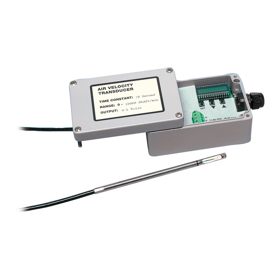
Parts Identification Carefully unpack the instrument and accessories. Check the parts against ® Figure 1. If any are missing or damaged notify your local distributor or TSI immediately. Figure 1/F 8455/65/75 Transducer 1980239 Manual 1309091 Probe mounting clips 5000285 #6 Sheet Metal... - Page 7 Figure 2: Inside of Electronic Enclosure 1. Setup/Troubleshooting Display 5. Programming Instructions (foldout) 2. Push-Buttons (SET, , ) 6. Compression Fitting (Power) 3. Terminal Block 7. Calibration Connector, Factory use 4. Mounting Holes only 1.800.544.2843 www.calcert.com sales@calcert.com...
- Page 8 Mounting the Transducer Electronics Enclosure The electronics enclosure should be mounted to a secure surface. W A R N I N G DO NOT change the length of the transducer probe cable. Changing the cable length will alter the performance and calibration of the Transducer. 5000285 1.800.544.2843 www.calcert.com...
-
Page 9: Mounting The Transducer Probe
Mounting the Transducer Probe The probe should be securely mounted before use. If mounted in a duct or pipe the probe should be at least 7.5 duct diameters downstream and 3 duct diameters upstream of anything that could cause flow turbulence. The orientation dot on the probe should face upstream. - Page 10 Wiring the Transducer Position the wires away from the SET - - push-buttons Power 11-30 VDC or 18-28 VAC 50/60 Hz, 350 mA Requirements Recommended 18 gauge shielded cable. To avoid electrical Wire interference, connect shield to ground on transducer and ground or minus(-) terminal on power supply.
- Page 11 Wiring for AC-Powered Operation Wiring for DC-Powered Operation Output Measuring Use a fully differential input device (no ground Device: connection, plus (+) and minus (-) terminals are independent), so the signal can float at the measuring device. If fully differential input is not available, current (mA) output should be selected.
- Page 12 Setting Up the Transducer Turn the transducer power supply on. The instrument will go through a preprogrammed power-up sequence. The internal display will sequence through the current settings: Calibration date “CALdAtE”, “=“, month and year “03.2013”(March 2013), measurement units “mEtErS”(m/s) or “FEET”(ft/min), “=“, selected output type and range “0-5V”...
- Page 13 More Detail on the Time Constant In order to make a fluctuating display easier to read, the output time constant can be set between 0.05 and 10 seconds. The time constant is actually an averaging period. The output is the average of readings taken over the last time-constant period.
- Page 14 More Detail on Span Adjustment A span factor can be entered to adjust the output signal up or down by fifteen percent. While the span factor is shown on the display, the transducer will measure velocity and output the appropriate voltage or current for that velocity.
-
Page 15: More Detail On Adjusting Output Signal At Zero Velocity
More Detail on Adjusting Output Signal at Zero Velocity In certain cases, the remote display will not read the same as the transducer display output at zero velocity. To correct this discrepancy you will need to adjust the output signal at zero velocity. Put the transducer into setup mode and sequence through the setup messages until “AdJUSt ZErO”... - Page 16 1.800.544.2843 www.calcert.com sales@calcert.com...
-
Page 17: Troubleshooting
Troubleshooting Symptom Possible Problem & Solutions No output or low output Incorrect input voltage Sensor positioned incorrectly Sensor not extended beyond protective shield Wrong output type/range selected Loose power or signal connections Incorrect full scale velocity range selected Displayed velocity is Internal display is for setup/troubleshooting hard to read only... - Page 18 Cleaning the Sensor Dust and dirt may build up on the sensor. If necessary, carefully clean the sensor using a soft bristle brush dipped in a mild solvent like alcohol. Recalibration ® To maintain a high degree of accuracy in your velocity measurements, TSI recommends that you have your instrument recalibrated annually.
- Page 19 Common specifications to all models Field Selectable Velocity Ranges Model 8455/8465 ... 0.125 m/s to 1.0, 1.25, 1.50, 2.0, 2.5, 3.0, 4.0, 5.0, 7.5, 10.0, 12.5, 15.0, 20.0, 25.0, 30.0, 40.0, 50.0 m/s (25 ft/min to 200, 250, 300, 400, 500, 750, 1000, 1250, 1500, 2000, 2500, 3000, 4000, 5000, 7500, 10000 ft/min) Model 8475 ....
Need help?
Do you have a question about the 8455 and is the answer not in the manual?
Questions and answers