
Related Manuals for EL-CELL ECD-3

Summary of Contents for EL-CELL ECD-3
- Page 1 User Manual Release 1.6 ECD-3 Electrochemical dilatometer © 2022 EL-Cell GmbH © 2017 EL-CELL GmbH...
- Page 2 The information in this manual has been carefully checked and believed to be accurate; however, no responsibility is assumed for inaccuracies. EL-Cell GmbH maintains the right to make changes without further notice to products described in this manual to improve reliability, function, or design. EL -Cell GmbH does not assume any liability arising from the use or application of this product.
-
Page 3: Table Of Contents
User Manual ECD-3 Content 1 Product description ............................4 2 Features ................................7 3 Technical data ..............................7 4 Safety Precautions ............................8 5 Unpacking................................ 8 6 Start-up and disassembly .......................... 11 7 Assembling the cell inside the glove box ..................... 19 8 Further assembly outside the glove box .................... -
Page 4: Product Description
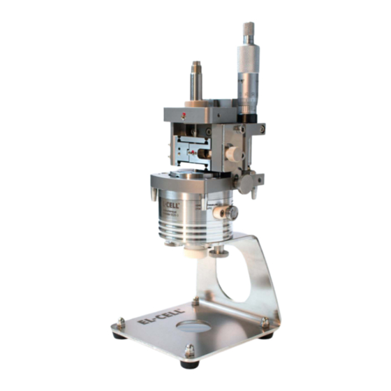
1 Product description The ECD-3 electrochemical dilatometer measures charge-induced strain (expansion and shrinkage) of electrodes down to the nanometer range. The ECD-3 has been mainly developed to investigate battery and other insertion-type electrodes. It may, however, also be used for many other electrochemical systems utilizing aprotic organic electrolyte solutions . - Page 5 User Manual ECD-3 The basic structure of the ECD-3: Sensor unit Details shown on the following page Cell body Bracket Page 5 of 47 Release 1.6...
- Page 6 User Manual ECD-3 Cut drawing of the ECD-3: Micrometer screw LVDT sensor Sensor plunger Excenter Flexure Load Locking screw Sensor Tip Spacer disc Glass-T-Frit Shut-off valve Reference electrode Piston Page 6 of 47 Release 1.6...
-
Page 7: Features
User Manual ECD-3 2 Features The ECD-3 is an electrochemical dilatometer for measuring changes in the thickness of the working electrode of a battery test cell. The main features of the ECD -3 are briefly described in the following: LVDT sensor system with <50 nm resolution, drift stability of <100 nm/hour (sample-free ▪... -
Page 8: Safety Precautions
Check the contents of the packages against the list given below to verify that you have received all of the required components. Contact EL-CELL if anything is missing or damaged. NOTE: Damaged shipments must remain within the original packaging for freight company inspection. - Page 9 9. Allen wrench 2.5 mm WZG9059 10. Allen wrench 3 mm WZG9058 11. 3 x PE Seal II ECD-3 piston ECC1-01-0044-D 12. 3 x PTFE Seal ECD-3 piston ECC1-00-0044-C 13. 1 x PTFE Seal ECD 33.3 x 1.8 mm (3 pcs.) ECC1-01-0043-D/3 14.
- Page 10 User Manual ECD-3 23. Allen wrench set (0.9 / 1.3 / 1.5 / 2) (4 pcs) ECC1-01-0028-A 24. Open end wrench AF7 ECC1-09-2037-A 25. Disassembly device piston ECC1-09-3048-A 26. Allen screwdriver 2.5 mm WZG9003 27. Spherical Allen screwdriver 3 mm WZG9002 28.
-
Page 11: Start-Up And Disassembly
Make sure you have understood the how and why of every single step. Ask us otherwise. 6.1 After unpacking the ECD-3, remove the transport lock from the sensor unit. 6.2 Unscrew the two inner screws first, only then the two outer screws. - Page 12 User Manual ECD-3 6.4 Screw off the cell body from the bracket. 6.5 Unscrew the spring load from the cell body. 6.6 Unscrew the reference electrode. 6.7 Remove the cover flange. Page 12 of 47 Release 1.6...
- Page 13 User Manual ECD-3 6.8 When dissassembling the dilatometer for the first time, remove the stiff plate below the cover flange. This plate is for transport only. For the actual experiment, replace the plate by the provided metal membrane. 6.9 Remove the stiff plate or membrane from the cell body 6.10 Now the frit flange with the PTFE-...
- Page 14 User Manual ECD-3 6.12 Loosen the socket screw at the end of the piston a little with the Allen wrench (half turn). This releases the disk springs inside piston and allows it to be pulled out. 6.13 Pull the piston out of the frit flange by using the dedicated removal tool.
- Page 15 User Manual ECD-3 6.15 Slide the locking disc completely over the tool as shown in the picture. 6.16 Unscrew the tool to remove the piston from the frit flange. Page 15 of 47 Release 1.6...
- Page 16 User Manual ECD-3 6.17 Remove the socket screw at the end of the piston and disassemble it. Both seals need to be renewed before each test. Page 16 of 47 Release 1.6...
- Page 17 User Manual ECD-3 The following steps 6.18 to 6.20 describe the disassembly of the base body, dead volume cover, and dead volume valve. The dead volume option is no longer used with the updated version of the dilatometer. Therefore, leave those parts in the assembled state. The valve does not need to be installed.
- Page 18 12.O-Ring 33.05 x 1.78 mm, EPDM on working electrode thickness) 13.Socket screw 3.T-frit 14.PE-Seal for ECD-3 (33 mm x 1.6 mm) 4.Cover the flange with three screws 15.Ferrule 1.5 mm, PTFE 5.Dead volume cover with three screws 16.Shut-off valve (Note: Not used with the updated version of the 6.ECD-3 base body...
-
Page 19: Assembling The Cell Inside The Glove Box
User Manual ECD-3 7 Assembling the cell inside the glove box After moving the different parts of the disassembled cell body into the glove box, follow the steps below. Protect yourself and handle the chemicals with care. 7.1 Inside the glove box: Insert the T-frit with the smaller side pointing downwards into the frit flange. - Page 20 User Manual ECD-3 7.4 Inside the glove box: First place the PE sealing (PE Seal II ECD-3 piston) followed by the PTFE sealing (17.PTFE Seal ECD-3 piston) on the piston. The outward curved side of the sealing rings must face away from the piston (see sketch below) 7.5 Inside the glove box: Add the thrust...
- Page 21 User Manual ECD-3 7.7 Inside the glove box: Attach the counter piston from below. Use the removal tool to push it. The piston must be pressed into the frit flange until the two sealing rings are no longer visible. Make sure that it is positioned straight in the frit flange.
- Page 22 User Manual ECD-3 7.10 Inside the glove box: : Add 320-420 μl of electrolyte using an pipette. 7.11 Inside the glove box: : Place the working electrode with the active side pointing downwards on top of the T-Frit. 7.12 Inside the glove box: : Insert the PTFE seal, make sure it is inserted correctly.
- Page 23 User Manual ECD-3 7.13 Inside the glove box: : Put the spacer disc on top of the electrode, make sure that it is placed in the center of the electrode. The proper spacer disc thickness depends on the working electrode thickness, see chapter 14.
- Page 24 User Manual ECD-3 7.16 Inside the glove box: Attach the reference pin gently to the cell body. Push onto the back of the reference pin while screwing it in. 7.17 Inside the glove box: Attach the cover flange. 7.18 Inside the glove box: Now close the cell body with the three cover screws.
- Page 25 User Manual ECD-3 7.19 Inside the glove box: After that, we recommend using the allen key to tighten the screws in small increments on all three sides until they reach the stop. 7.20 Inside the glove box: Then check that the cell cover is firmly seated on the housing and that no gap is visible.
- Page 26 User Manual ECD-3 7.22 Inside the glove box: Now screw in the spring load into the cell base. 7.25 Inside the glove box: The cell is now assembled and hermetically sealed, and can be removed from the glove box. Page 26 of 47...
-
Page 27: Further Assembly Outside The Glove Box
User Manual ECD-3 8 Further assembly outside the glove box 8.1 Hook the assembly into the bracket and fasten it with the two knurled screws. 8.2 Unlock the locking screw (1) and the excenter (2). Then turn the micrometer screw (3) clockwise until the sensor tip is in the upmost position. - Page 28 8.4 Fasten the screws to fix the sensor unit. Then connect all cables as shown in the photo below. We highly recommend operating the dilatometer in a temperature-controlled environment. 1.ECD-3 cell cable 2.ECD sensor cable 3.Power supply + power supply adapter 4.USB cable 5.Example: Individual Biologic data logger cable...
- Page 29 8.7 The sensor position is indicated by the LED bar graph indicator at the electronic box of the ECD-3. Any yellow LED indicates a valid position. For best accuracy and resolution, adjust the sensor approximately in central position.
- Page 30 User Manual ECD-3 8.8 Example: Connecting a Biologic data logger cable (available on request). View the whole wiring on page 28. Finally, connect your potentiostat or battery tester to the 4 mm jacks on the front panel of the controller box. Make sure that both instruments share a common ground (GND) potential.
-
Page 31: Ec-Link Software Installation
The following combination of the ECD-3 with a Biologic potentiostat (MPG-2, SP, VSP and VMP series) is described as an example. The Biologic potentiostats feature two analog inputs used here to record displacement and temperature. - Page 32 2. In the Biologic EC-Lab software, load the experiment settings ECD*.mps provided on the ECD-3 installation media. The settings are shown in the External Devices dialog . Adapt the Parameter Settings of the charge/ discharge protocol to your particular experiment, if necessary.
-
Page 33: Using The Reference Electrode
Components of the reference electrode: Ferrule 1.5 (short top part) ECC1-00-0029-H Fitting long II (with cone) ECC1-00-0039-N Ref pin ECD, long (1.4404) ECD1-00-0050-A Compression spring (1.4310/ Au) FED9017 Reference connection tip ECC1-00-0331-A Hollow screw ECD-3 ECC1-00-0040-A Page 33 of 47 Release 1.6... -
Page 34: Using The Valve
User Manual ECD-3 Using the valve The shut-off valve is no longer used in the updated version (2022). The following points refer only to the case where you want to use the instrument in the old configuration with dead volume. -
Page 35: Choosing The Appropriate Spacer Disc
User Manual ECD-3 Choosing the appropriate spacer disc To achieve electrical contact between the electrode and the membrane, it is essential to fill the 2.7 mm gap between the T-Frit and the Membrane. This is achieved by the stack comprised of the spacer disc (current collector) and the working electrode. -
Page 36: Dilatometer Disassembly And Cleaning
User Manual ECD-3 Dilatometer Disassembly and Cleaning When disassembling the dilatometer cell, wear protective gloves and glasses . Collect parts that have been in contact with electrolytes on a separate tray for subsequent cleaning. 1. Disconnect all cables from the dilatometer cell and the sensor unit. -
Page 37: Care Instructions
▪ O-Ring 50.5 x 1.78 mm (10 pcs) DIC9038/X ▪ PTFE seal for ECD (33 x 1.6) (3 pcs) ECC1-01-0043-D/3 ▪ PTFE seal for ECD-3 piston (3 pcs) ECC1-01-0044-C/3 ▪ Spacer disc (set) 2.1-2.7 ECC1-01-0374-A ▪ Spacer disc (set) 2.1-2.3 ECC1-01-0012-F ▪... -
Page 38: Spare Parts
User Manual ECD-3 18 Spare Parts Components Sensor Unit There are no further spare parts available for the sensor unit. For repair, please contact EL-CELL. Socket screw DIN-912 M4x12 Page 38 of 47 Release 1.6... - Page 39 User Manual ECD-3 Components Cell Body ECD3-00-0002-A Page 39 of 47 Release 1.6...
- Page 40 User Manual ECD-3 Shut-off valve (ECD-3), assy ECC1-00-0155-B Ferrule plug 1.0 ECC1-00-0029-B O-Ring 5x1 mm (AP370) DIC9036 Valve Seating ECD-3 ECC1-00-0153-C O-Ring 2x1 mm (AP312) DIC9037 Valve Stem ECD ECC1-00-0063-B Page 40 of 47 Release 1.6...
- Page 41 User Manual ECD-3 Central CE piston ECD-3 (PE-sealed), screwed ECD3-00-0006-D Page 41 of 47 Release 1.6...
- Page 42 User Manual ECD-3 Spring load (ECD-3), assy ECD3-00-0008-A Compression Spring 1.2 x 9.8 x 19.2 x 3.5 (AU) FED9021 Spring Ram (ECD-3) ECC1-00-0022-E O-Ring 6.75 x 1.78 mm (AP380) DIC9039 O-Ring 14 x 1.5 mm (AP370) DIC9032 Spring Ram (ECD-3)
- Page 43 REF electrode ECD, long, assy (1.4404) ECD1-00-0009-D Ferrule 1.5 (short top part) ECC1-00-0029-H Fitting long II (with cone) ECC1-00-0039-N Ref pin ECD, long (1.4404) ECD1-00-0050-A Compression spring (1.4310/ Au) FED9017 Reference connection tip ECC1-00-0331-A Hollow screw ECD-3 ECC1-00-0040-A Page 43 of 47 Release 1.6...
-
Page 44: Connector And Cable Pin-Out
User Manual ECD-3 19 Connector and Cable Pin-out Sensor Cable (5 x 1 x 0.14 mm , shielded): ECE1-00-0036-A One end of the cable is terminated by a SUB -D F15 connector (to box); the other end is terminated by a round Binder series 712 connector (to LVDT sensor). The cable shield is tied to both connector housings. - Page 45 User Manual ECD-3 Cell Cable (4 x 2 x 0.25 mm , TP, shielded): ECE1-00-0033-F One end of the cable is terminated by a Sub-D HD M15 connector (to box); 2 mm banana connectors terminate the other end. A Pt100 sensor is located beneath the black shrink tube at the end of the cable pointing to the dilatometer.
- Page 46 User Manual ECD-3 Biologic Auxiliary Cable (2 x 2 x 0.14 mm , TP, shielded): ECE1-00-0039-B One end of the cable is terminated by a Sub-D HD F15 connector (to the data logger connector at the controller box); the other end is terminated by a Sub -D M9 connector (to the auxiliary input connector of the Biologic potentiostat).
-
Page 47: Technical Support
21 Warranty For a period of one year from the date of shipment, EL-Cell GmbH (hereinafter Seller) warrants the goods to be free from defect in material and workmanship to the original purchaser. During the warranty period, Seller agrees to repair or replace defective and/or nonconforming goods or parts without charge for material or labor, or, at the Seller’s option, demand return...
Need help?
Do you have a question about the ECD-3 and is the answer not in the manual?
Questions and answers