
Related Manuals for EL-CELL PAT-Press


Summary of Contents for EL-CELL PAT-Press
- Page 1 User Manual Release 1.34 PAT-Press Single cell package for monitoring the pressure build-up and drawing gas samples using the PAT-Cell-Press © 2018 EL-CELL GmbH...
- Page 2 The information in this manual has been carefully checked and believed to be accurate; however, no responsibility is assumed for inaccuracies. EL-CELL GmbH maintains the right to make changes without further notice to products described in this manual to improve reliability, function, or design. EL -CELL GmbH does not assume any liability arising from the use or application of this product.
-
Page 3: Table Of Contents
User Manual PAT-Press Content 1 Product description ............................4 2 Assembly and installation ........................... 5 3 PAT-Press Box ..............................6 4 Unpacking................................ 9 5 Accessories ..............................10 6 Technical support ............................10 7 Warranty ................................ 11 Included component manuals PAT-Stand-1…………………………………………………………………………………………………………………………………….. -
Page 4: Product Description
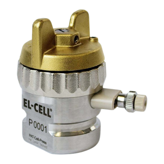
User Manual PAT-Press 1 Product description The PAT-Press is a complete package for recording the pressure rise during battery formation and cycling, and for drawing gas samples from the headspace of the test cell. PAT-Cell-Press (test cell) PAT-Press Box (conditioning electronics, data logger) -
Page 5: Assembly And Installation
With the provided cable, connect the the PAT-Stand-1 inside the chamber to the PAT- Press Box outside the chamber. Connect the PAT-Press Box to the provided 24V power supply (wall adapter) and to an USB port at your Windows PC. -
Page 6: Pat-Press Box
The pressure and temperature signals are also available at the Analog Out connector of the PAT-Press Box. IF the used battery tester or potentiostat features auxiliary analog inputs, then it is possible to directly record and display the pressure and temperature with the software application of the battery tester or potentiostat. - Page 7 User Manual PAT-Press Connectors Banana sockets (2 or 4 mm) at the box cover (Table shows standard connection to potentiostat or battery tester for full cell control) PAT-Press Box, banana sockets at Potentiostat Battery tester PAT-Core connection the box cover...
- Page 8 User Manual PAT-Press Cell connector (Sub-D M15) at the front of the box Pin # Signal Comments Sense lead to lower electrode of PAT-Core Sense lead to upper electrode Sense lead to reference ring Current lead to upper electrode Raw signal from pressure transducer inside PAT-Cell-Press test cell...
-
Page 9: Unpacking
Check the contents of the packages against the list given below to verify that you have received all of the required components. Contact EL-CELL, if anything is missing or damaged. NOTE: Damaged shipments must remain within the original packaging for freight company inspection. -
Page 10: Accessories
0.. 10 V; 8°C/V Analog IN 1 0.. 10 V; 0.25 bar/V 6 Technical support Technical support for this product is exclusively provided by EL-CELL GmbH. EL-CELL GmbH Tempowerkring 8 21079 Hamburg - Germany phone: +49 (0)40 790 12 733... -
Page 11: Warranty
PAT-Press 7 Warranty For a period of one year from the date of shipment, EL-CELL GmbH (hereinafter Seller) warrants the goods to be free from defect in material and workmanship to the original purchaser. During the warranty period, Seller agrees to repair or replace defective and/or nonconforming goods or parts without charge for material or labor, or, at the Seller’s option,... -
Page 12: Pat-Stand
User Manual Release 1.5 PAT-Stand-1 Docking station for PAT series test cells © 2017 EL-CELL GmbH... - Page 13 The information in this manual has been carefully checked and believed to be accurate; however, no responsibility is assumed for inaccuracies. EL-CELL GmbH maintains the right to make changes without further notice to products described in this manual to improve reliability, function, or design. EL -CELL GmbH does not assume any liability arising from the use or application of this product.
- Page 14 User Manual PAT-Stand-1 Content 1 Product description ............................4 2 Installation ............................... 5 3 Cleaning ................................5 4 Operation modes ............................6 5 Cable colors and naming conventions ....................7 6 Unpacking................................ 8 7 Technical data ..............................8 8 Spare parts ..............................8 9 Technical support ............................
-
Page 15: Product Description
The PAT-Stand-1 is the docking station for a single PAT series test cell. When docked into the PAT-Stand-1, the test cell may be tested by any potentiostat or battery tester. The compatible test cells and the PAT-Core concept are covered in detail by other manuals: (http://el-cell.com/downloads/downloads-manuals). PAT-Cell PAT-Stand-1... -
Page 16: Installation
User Manual PAT-Stand-1 2 Installation Place the PAT-Stand-1 on a flat, dry and clean surface, for example on a bench top, inside a temperature chamber or a glove box. Then conncet the cell cable of your potentiostat or battery tester channel to the banana sockets at the front of the PAT-Stand-1. Pin-Out of Sub-D F15 HD Connector “Cell”... -
Page 17: Operation Modes
User Manual PAT-Stand-1 4 Operation modes Connect the cell cable of your potentiostat or battery tester channel to the banana sockets at the front of the PAT-Stand-1. For the different operation modes, see the table below. Operation mode 1: Cell voltage control (1 vs 2) PAT-Stand-1 Potentiostat WE-Sense... -
Page 18: Cable Colors And Naming Conventions
User Manual PAT-Stand-1 5 Cable colors and naming conventions The naming convention and color codes of the potentiostat´s cell cable leads are not standardized between different manufacturers. The table below is an incomplete list of some popular instruments. Important note: The application of our test cells is not limited to the potentiostats listed below. -
Page 19: Unpacking
Check the contents of the packages against the list given below to verify that you have received all of the required components. Contact EL-CELL, if anything is missing or damaged. NOTE: Damaged shipments must remain within the original packaging for freight company inspection. -
Page 20: Technical Support
10 Warranty For a period of one year from the date of shipment, EL-CELL GmbH (hereinafter Seller) warrants the goods to be free from defect in material and workmanship to the original purchaser. During the warranty period, Seller agrees to repair or replace defective and/or nonconforming goods or parts without charge for material or labor, or, at the Seller’s option,... -
Page 21: Pat-Cell-Press
User Manual Release 1.21 PAT-Cell-Press Electrochemical test cell © 2018 EL-CELL GmbH... - Page 22 The information in this manual has been carefully checked and believed to be accurate; however, no responsibility is assumed for inaccuracies. EL-CELL GmbH maintains the right to make changes without further notice to products described in this manual to improve reliability, function, or design. EL -CELL GmbH does not assume any liability arising from the use or application of this product.
- Page 23 User Manual PAT-Cell-Press Content 1 Product description ............................4 2 Safety precautions............................5 3 Assembly of the PAT-Cell-Press ........................ 5 4 Disassembly and cleaning ........................... 6 5 Sample valve with septum port ......................... 7 6 Unpacking................................ 8 7 Spare parts and consumables ........................9 8 Technical support ............................
-
Page 24: Product Description
Helium leak tested* Can be used in single-channel configuration together with the PAT-Stand-1 and the PAT-Press box 16 and Can be used in multi-channel configuration in the PAT-Chamber- PAT-Tester-i-16 *The PAT-Cell-Press has been tested for leakage at the factory. For an empty cell, pressurized with air through the sample port by means of a syringe, at 2 bar absolute, at 50°C, the pressure decay after 24... -
Page 25: Safety Precautions
User Manual PAT-Cell-Press 2 Safety precautions Use proper safety precautions when using hazardous electrode materials and electrolytes. Wear protective glasses and gloves to protect you against electrolyte that may accidentally spill out during disassembly. Upon cell disassembly, dispose all materials properly. Metallic lithium and some insertion compounds may decompose heavily in contact with water and other solvents, and can cause fire. -
Page 26: Disassembly And Cleaning
User Manual PAT-Cell-Press Put the insulation sleeve onto the worktop with the smaller side pointing upwards. Different insulation sleeves are available for different test purposes, see chapters 6 and 7. Insert the lower electrode into the sleeve with the active layer facing downwards. Attach the lower plunger. -
Page 27: Sample Valve With Septum Port
The gas sample valve serves to draw gas samples for further characterization from the head space of the test cell. Ferrule 1.0 Valve Seating Valve Stem PAT-Press Septum Septum Thrust Screw II Gas sample port (PAT-Cell-Press) ECC1-00-0155-C In the closed state, the valve spindle is seated on the PTFE ferrule and is thus preventing any bleeding through the pierced septum. -
Page 28: Unpacking
Check the contents of the packages against the list given below to verify that you have received all of the required components. Contact EL-CELL, if anything is missing or damaged. NOTE: Damaged shipments must remain within the original packaging for freight company inspection. -
Page 29: Spare Parts And Consumables
User Manual PAT-Cell-Press 7 Spare parts and consumables Screw cap (PAT), complete ECC1-00-0236-B Page 9 of 13 Release 1.21... - Page 30 User Manual PAT-Cell-Press Cell base GTMS (PAT-Press), assy ECC1-00-0255-A Page 10 of 13 Release 1.21...
- Page 31 User Manual PAT-Cell-Press Spring contact pin holder, assy ECC1-00-0410-A Page 11 of 13 Release 1.21...
- Page 32 User Manual PAT-Cell-Press Gas sample port (PAT-Press), assy ECC1-00-0155-C Page 12 of 13 Release 1.21...
-
Page 33: Technical Support
9 Warranty For a period of one year from the date of shipment, EL-CELL GmbH (hereinafter Seller) warrants the goods to be free from defect in material and workmanship to the original purchaser. During the warranty period, Seller agrees to repair or replace defective and/or nonconforming goods or parts without charge for material or labor, or, at the Seller’s option,... - Page 34 User Manual Release 1.21 PAT-Core Insulation sleeve with built-in separator and optional reference electrode and current collectors © 2018 EL-CELL GmbH © 2017 EL-CELL GmbH...
- Page 35 The information in this manual has been carefully checked and believed to be accurate; however, no responsibility is assumed for inaccuracies. EL-CELL GmbH maintains the right to make changes without further notice to products described in this manual to improve reliability, function, or design. EL -CELL GmbH does not assume any liability arising from the use or application of this product.
- Page 36 User Manual PAT-Core Content 1 Product description ............................4 2 PAT-Core components ..........................4 3 Unpacking................................ 6 4 Pre-use treatment ............................6 5 Assembly instructions ..........................6 6 Disassembly and cleaning ......................... 14 7 Common test cases ............................. 15 8 Separator features ............................19 9 PAT Components overview ........................
-
Page 37: Product Description
User Manual PAT-Core 1 Product description The PAT-Core is the essential part of the PAT-Cell holding in place and precisely aligning the electrodes under test. The well-defined geometry of the PAT-Core enables high-quality two- and three-electrode tests of Li-ion and other battery materials as well as supercapacitors . 2 PAT-Core components Every PAT-Core consists of three main parts, all available in different materials. - Page 38 User Manual PAT-Core 2.1 Upper plunger By default, the upper plunger serves as the negative current collector. The given size fits for any thickness of the upper electrode up to 800 µm. The plungers are available in Stainless Steel (ss), Al and Cu, and as a special version made of PEEK polymer. The PEEK plungers are used in combination with a disc-shaped metal foil as the current collector.
-
Page 39: Unpacking
User Manual PAT-Core For a separator thickness below 100 µm: Height number = Thickness of lower electrode (in µm) + 50 For a separator thickness above 100 µm: Height number = Thickness of lower electrode (in µm) + half of the separator thickness (in µm) Example: You are using an insulation sleeve with 260 µm glass fiber together with a 90 µm thick LCO cathode. - Page 40 User Manual PAT-Core 5.1 Safety precautions Use proper safety precautions when using hazardous electrode materials and electrolytes. Wear protective glasses and gloves to protect you against electrolyte that may accidentally spill out during disassembly. Upon cell disassembly, dispose all mate rials properly. Metallic lithium and some insertion compounds may decompose heavily in contact with water and other solvents, and can cause fire.
- Page 41 User Manual PAT-Core 2. Insert the upper disc spring. Make sure the three tabs of the disc spring are properly snapped in. Lower PEEK plunger assembly 1. Insert the lower feed wire into the hole of the lower plunger. Note the correct orientation. 2.
- Page 42 User Manual PAT-Core Upper PEEK plunger disassembly 1. Lever out the three tabs of the disc spring and remove the disc spring. 2. Remove the upper feed wire. Lower PEEK plunger disassembly 1. Turn the disc spring counter-clockwise by 45 degrees and lift it out. Page 9 of 23 Release 1.21...
- Page 43 User Manual PAT-Core 2. Remove the lower feed wire. 5.3 PEEK insulation sleeve assembly The following steps describe the assembly of the PEEK insulation sleeves. Note: For use with aprotic electrolytes, stick rings and separator must be properly dried upfront, and assembly of the sleeve must be carried out inside a glove box. Recommended drying conditions: Overnight, vacuum, 80°C for stick rings;...
- Page 44 User Manual PAT-Core 1. Insert the reed contact into the outer stick ring 2. Insert the Reference ring on top of the assembly. 3. Insert the separator with diameter 21.6 mm. Page 11 of 23 Release 1.21...
- Page 45 User Manual PAT-Core 4. Put the inner stick ring on top and press it down. Check the proper position of the contact tongue. Page 12 of 23 Release 1.21...
- Page 46 User Manual PAT-Core 5.4 Standard assembly 1. Put the insulation sleeve (6) onto the worktop with the smaller side pointing upwards. 2. Insert the lower electrode (7) into the sleeve with the active layer facing downwards. 3. Attach the lower plunger (8). The lower plunger is available in different gap sizes in order to account for the thickness of the lower electrode and the separator used.
-
Page 47: Disassembly And Cleaning
User Manual PAT-Core 6 Disassembly and cleaning After disassembly, dispose all single-use components and electrodes properly. If the cell base has got contaminated with electrolyte, clean it with plenty of water and dry with compressed air. Use less electrolyte for subsequent tests. Plungers made of stainless steel have to be cleaned with plenty of water. -
Page 48: Common Test Cases
User Manual PAT-Core 7 Common test cases These tables show recommended PAT-Core components for the most common testing scenarios and can be used as a guide for building PAT -Cell test cells. 7.1 Testing with aprotic LiPF based electrolytes Lower electrode LCO/NCM/LFP/.. - Page 49 User Manual PAT-Core 7.2 Testing with aprotic supercap electrolytes Lower electrode (+) Activated Carbon (AC) Upper electrode (-) Lower plunger SS or Al Upper plunger SS or Al Reference Activated carbon on stainless steel Separator FS-5P T/°C <70°C Lid seal Insulation sleeve PP (AC(SS)-Reference ring, Separator FS-5P) (10 pcs) Sleeve (single-use)
- Page 50 User Manual PAT-Core 7.3 Testing with aqueous supercap electrolytes Lower electrode (+) Upper electrode (-) Lower plunger PEEK Upper plunger PEEK Current collector disc Reference GF/A Separator ECC1-01-0011-A/L T/°C <70°C Lid seal Plain Insulation sleeve PEEK, disassembled Sleeve (reusable) ECC1-00-0510-T Au plated SS Reed contact ECC1-00-0186-D/X...
- Page 51 User Manual PAT-Core 7.4 Testing with aprotic high-temperature electrolytes Lower electrode (+) LCO/NCM/LFP.. Upper electrode (-) Graphite/LTO Lower plunger SS or Al Upper plunger SS or Cu Reference Li metal GF/A Separator ECC1-01-0011-A/L T/°C <200°C Lid seal PEEK or PTFE Plain Insulation sleeve PEEK, disassembled Sleeve (reusable) ECC1-00-0510-T...
-
Page 52: Separator Features
User Manual PAT-Core 8 Separator features FS-5P (Freudenberg Viledon FS Freudenberg Viledon FS Separator Whatman GF/A 2226E+Lydall Solupor 5P09B) 3005-25 Thickness 220µm 25µm 260µm Material PP fiber/PE membrane PET fiber/Al Borosilicate glass fiber Porosity FS: 67%/ 5P: 86% Wettability Good Good Excellent Resistance to dendrites... -
Page 53: Pat Components Overview
User Manual PAT-Core 9 PAT Components overview The listed items are only an excerpt of the available product range. Please visit el-cell.com more information. 9.1 Upper plunger Article Name Material Usage Order number Upper plunger, Cu Copper (Cu >99.9%, E-CU 58) - Page 54 User Manual PAT-Core 9.3 Current collector discs These discs are for use with PEEK plungers. Other materials are available on request. Article Name Material Usage Order number Current collector 18 mm, Au (5 pcs) Gold (Au>99%) Reusable ECC1-00-0069-A/V Current collector 18 mm, Ti (5 pcs) Titanium (Ti >99%, grade 2) Reusable ECC1-00-0069-C/V...
- Page 55 User Manual PAT-Core 9.6 Insulation sleeves Separator Article Name Reference material Separator material Order number thickness Insulation sleeve PP (Li-Reference, Li metal PET fiber/Al 25 µm ECC1-00-0210-A/X Separator FS 3005-25) (10 pcs) Insulation sleeve PP (Separator FS PET fiber/Al 25 µm ECC1-00-0210-B/X 3005-25) (10 pcs) Plain Insulation sleeve PP...
-
Page 56: Technical Support
11 Warranty For a period of one year from the date of shipment, EL-CELL GmbH (hereinafter Seller) warrants the goods to be free from defect in material and workmanship to the original purchaser. During the warranty period, Seller agrees to repair or replace defective and/or nonconforming goods or parts without charge for material or labor, or, at the Seller’s option,... - Page 57 © 2016 EL-CELL GmbH Quick Guide EC-Link Software Release 2.52 Using with PAT-Press, ECC-Press-DL, ECD-3, ECD-3-nano, ECD-2-DL, ECD-nano-DL © 2018 EL-CELL GmbH...
- Page 58 EL-CELL GmbH maintains the right to make changes without further notice to products described in this manual to improve reliability, function, or design. EL-CELL GmbH does not assume any liability arising from the use or application of this product.
- Page 59 Quick Guide EC-Link-Software (PAT-Press, ECC-Press-DL, ECD-3, ECD-3-nano) Content 1 What is EC-Link? ............................4 2 EC-Link System Requirements ........................4 3 Installing the EC-Link Software ......................... 4 4 Running the EC-Link Software ........................5 5 Log files ................................7 6 Settings ................................9 7 Post-Process ..............................
-
Page 60: What Is Ec-Link
Quick Guide EC-Link-Software (PAT-Press, ECC-Press-DL, ECD-3, ECD-3-nano) 1 What is EC-Link? EC-Link is the data logger software coming with the following instruments . PAT-Press ECC-Press-DL ECD-3, ECD-3-nano, ECD-2-DL, ECD-nano-DL PAT-Stand-16 / PAT-Tray, PAT-Chamber-16 (see separate quick start guide) ... -
Page 61: Running The Ec-Link Software
Quick Guide EC-Link-Software (PAT-Press, ECC-Press-DL, ECD-3, ECD-3-nano) 4 Running the EC-Link Software In the leftmost column, checkmark the channels you want to log . This setting cannot be changed while logging. In the second left column, checkmark the channels to view. This setting can be changed at any time. - Page 62 Quick Guide EC-Link-Software (PAT-Press, ECC-Press-DL, ECD-3, ECD-3-nano) ‘Cycle starts with charge (current > 0)’ applies to full cells (such as LCO vs Graphite) and “cathode” half cells (such as LCO vs Lithium). ‘ Cycle starts with discharge (current <...
-
Page 63: Log Files
Quick Guide EC-Link-Software (PAT-Press, ECC-Press-DL, ECD-3, ECD-3-nano) 10. Clicking the ‘Autoscale selected Channel’ button will affect the data in the presently displayed time window only. 11. Click the ‘View File’ button to view the log file data in text format. - Page 64 Quick Guide EC-Link-Software (PAT-Press, ECC-Press-DL, ECD-3, ECD-3-nano) *_Small.txt contains the reduced (compressed) data with varying time interval between data rows. Format: same as *.txt *-Cycle.txt contains the “cycle-wise” computed integral data Format (Columns): Cycle ─ Time (s) ─...
-
Page 65: Settings
Quick Guide EC-Link-Software (PAT-Press, ECC-Press-DL, ECD-3, ECD-3-nano) *-C2R.txt contains the differential capacitance data of the negative half cell Format (Columns): Cycle ─ Time (s) ─ t_cycle (s) ─ V2R (V) ─ Delta V2R (V) ─ Delta Q (mAh) ─... - Page 66 Quick Guide EC-Link-Software (PAT-Press, ECC-Press-DL, ECD-3, ECD-3-nano) In the Settings/Program dialog, you can select additional columns to be logged into the *.txt and *_Small.txt log files. The UTC time format is especially useful in case different consecutive measurements need to be referred to the same time scale.
-
Page 67: Post-Process
Quick Guide EC-Link-Software (PAT-Press, ECC-Press-DL, ECD-3, ECD-3-nano) 7 Post-Process In the headline of the program window, click the ‘Post-Process’ button in order to re-process existing *.txt log files using new processing parameters. Note that this function can only be applied on the original (uncompressed) *.txt log files. -
Page 68: Running Multiple Data Loggers
Quick Guide EC-Link-Software (PAT-Press, ECC-Press-DL, ECD-3, ECD-3-nano) 8 Running Multiple Data Loggers It is possible to connect multiple USB data loggers (and associated instruments) to a single PC and to run them simultaneously. The EC-Link software only needs to be installed once.
Need help?
Do you have a question about the PAT-Press and is the answer not in the manual?
Questions and answers