
Related Manuals for Leonton PT2-0802-M-24 Series


Summary of Contents for Leonton PT2-0802-M-24 Series
- Page 1 Leonton PT2-0802-M-24 Series (PT2-0802-M-24 / PT2-0802-M-24-T) User Manual Version 1.0...
- Page 2 Disclaimer Leonton Technologies, Co. Ltd. provides this manual without warranty of any kind, expressed or implied, including but not limited to the implied warranties of merchantability and fitness for a particular purpose.
- Page 3 This is a Class-A product. In a domestic environment this product may cause radio interference in which case the user may be required to take adequate measures. This document is the current official release manual. Please check our website (www.leonton.com) for any updated manual or contact us by e-mail (sales@leonton.com).
-
Page 4: Table Of Contents
Contents Overview ........................1 Key Features ......................1 Package Contents ..................... 2 Safety Precaution ..................... 2 Hardware Description ....................3 Physical Dimensions ....................3 Front Panel ....................... 4 Top View ........................4 LED Indicators ......................5 Ethernet Ports ......................5 Cabling ........................ -
Page 5: Overview
Overview This series is rated IP30 and installation by DIN Rail. Each unit of this industrial unmanaged Ethernet switch series has 6*10/100Tx with IEEE 802.3at compliant ports (30W/port) and 2*100Fx of SC or ST type connector and support Multi-mode or Single-mode, which the RJ-45 interface provides auto detection of MDI or MDI-X. -
Page 6: Package Contents
Package Contents 1 - PT2-0802-M-24(-T) 2 - Wall mounting brackets and screws Safety Precaution Attention If the DC voltage is supplied by an external circuit, please use a protection device on the power supply input. Supply by UL Listed industrial use power. The industrial Ethernet switch’s hardware specs, ports, cabling information, and wiring installation will be described within this user manual. -
Page 7: Hardware Description
Hardware Description Physical Dimensions Figure 2.1, below, shows the physical dimensions of PT2-0802-M-24 series. (W x H x D) is 46mm x 142mm x 99mm Figure 2.1: PT2-0802-M-24 Series Physical Dimensions... -
Page 8: Front Panel
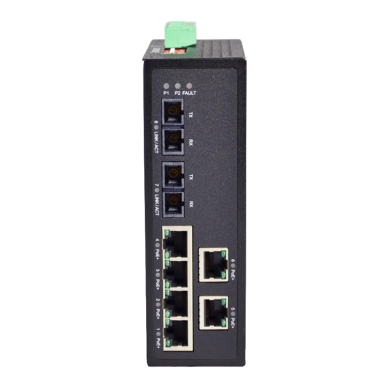
Figure 2.2: The Front Panel of PT2-0802-M-24 Series Top View Figure 2.3, below, shows the top panel of the PT2-0802-M-24 series switch that is equipped with one 6-pin removal terminal block connector for dual DC power inputs (12-36VDC). Figure 2.3: Top Panel View of PT2-0802-M-24 Series... -
Page 9: Led Indicators
Flashing Networking is active Green LINK/ACT Not connected to network Table 2.1: LED Indictors for PT2-0802-M-24 Series Ethernet Ports RJ-45 Ports (Auto MDI/MDIX) The RJ-45 ports are auto-sensing for 10Base-T, 100Base-TX or 1000Base-T devices connections. Auto MDI/MDIX means that the switch can connect to another switch or workstation without changing the straight-through or crossover cabling. - Page 10 10/100BASE-T(X) RJ-45 Pin Assignments (Table 2.2) Crossover Cable Straight Through Cable Pin Number / Signal Pin Number / Signal Pin Number / Signal Pin Number / Signal 1 / RX+ 3 / TX+ 1 / RX+ 1 / TX+ 2 / RX- 6 / TX- 2 / RX- 2 / TX-...
-
Page 11: Cabling
Cabling Use the four twisted-pair, category 5e, or the above cabling for RJ-45 port connections. The cable between the switch and the link partner (switch, hub, workstation, etc.) must be less than 100 meters (328 ft.) long. Wiring the Power Inputs Please follow the below steps to insert the power wire. -
Page 12: Wiring The Fault Alarm Contact
Wiring the Fault Alarm Contact The fault alarm contact is in the middle of the terminal block connector as the picture shows below in Figure 2.16. By inserting the wires, it will detect the fault status including power failure or port link failure (managed industrial switch only) and form a normally open circuit. -
Page 13: Dip Switch Settings
DIP Switch Settings The following describes the DIP switch settings. ON: Enables the corresponding PORT alarm. If the port’s link fails, the relay will form an open circuit and the fault LED will turn on. Off: Disables the corresponding PORT alarm. The relay will form a closed circuit and the fault LED will never turn on. -
Page 14: Mounting Installation
Mounting Installation DIN-Rail Mounting The DIN-Rail is pre-installed on the industrial Ethernet switch from the factory. If the DIN-Rail is not on the industrial Ethernet switch, please see Figure 3.1 to learn how to install the DIN-Rail on the switch. Figure 3.1: The Rear Side of the Switch and DIN-Rail Bracket Follow the steps below to learn how to hang the industrial Ethernet switch. - Page 15 Figure 3.2: Insert the Switch on the DIN-Rail Lightly pull down the bracket on to the rail as shown below in Figure 3.3. Step 4. Figure 3.3: Stable the Switch on DIN-Rail Check if the bracket is mounted tightly on the rail. Step 5.
-
Page 16: Wall Mounting
Wall Mounting Follow the steps below to mount the industrial Ethernet switch using the wall mounting bracket as shown below in Figure 3.4. Remove the DIN-Rail bracket from the industrial Ethernet switch by loosening the screws. Step 1. Place the wall mounting brackets on the top and bottom of the industrial Ethernet switch. Step 2. -
Page 17: Hardware Installation
Hardware Installation Installation Steps This section will explain how to install PT2-0802-M-24 series. Installation Steps Unpack the industrial Ethernet switch from the original packing box. Step 1. Check if the DIN-Rail bracket is screwed on the industrial Ethernet switch. Step 2. -
Page 18: Trouble Shooting
Check for loose power connections, power losses or surges at the power outlet. ◆ Please contact Leonton for technical support service, if the problem still cannot be resolved. ● If the industrial switch LED indicators are normal and the connected cables are correct but the packets still cannot transmit, please check the system’s Ethernet devices’...
Need help?
Do you have a question about the PT2-0802-M-24 Series and is the answer not in the manual?
Questions and answers