Advertisement
Quick Links
RENEWAL PARTS IDENTIFICATION
Boiler Serial No . . . . . . . . . . . . . . . . . . . . . . . . . . . . . . . . . . . . . . . . . . . . Power Circuit Voltage . . . . . . . . . . . . . . . . . . . . . . . . . . . . . . . . . . . . . . . .
Model No. . . . . . . . . . . . . . . . . . . . . . . . . . . . . . . . . . . . . . . . . . . . . . . . . No. of Power Circuits . . . . . . . . . . . . . . . Amps. . . . . . . . . . . . . . . . . . . .
Electrical Capacity . . . . . . . . . . . . . . . . . . . . . . . . . . . . . . . . . . . . . . . . . . Control Circuit Voltage . . . . . . . . . . . . . . . . . . . . . . . . . . . . . . . . . . . . . . .
National Board No . . . . . . . . . . . . . . . . . . . . . . . . . . . . . . . . . . . . . . . . . . Total Amps . . . . . . . . . . . . . . . Phase . . . . . . . . . . . . Cy . . . . . . . . . . . . .
IMPORTANT – This data file contains the National Board Registration Certificate approving your generator. It must be kept near the generator at all times.
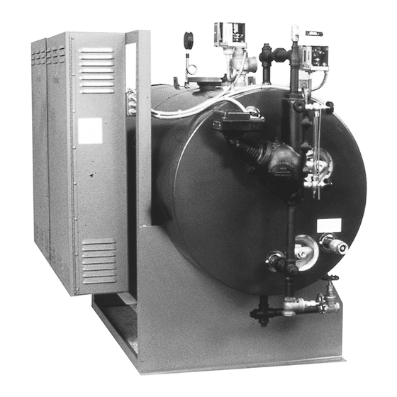
CHS-360 Steam Boiler
CAUTION: To avoid electrical shock hazard, boilers
must be suitably grounded to earth.
NOTE: Chromalox boilers are pre-tested before shipment; no internal
piping or wiring is necessary. WARNING: Substitution of compo-
nents or modification of wiring without prior consent of Chromalox,
Inc. voids warranty.
1. Locate unit on level floor or platform. NOTE: A minimum dis-
tance of 60 inches from wall, other equipment, etc. must be
allowed for removal of the elements.
2. Complete all piping to boiler. Connect water line to tagged fitting
on the motor and pump assembly, if used, or to tagged fitting on
water control feeder.
© 2010 Chromalox, Inc.
Installation, Operation
and
Horizontal Electric Steam Boiler
Model Number CHS 0 – 150 PSI
Specifications — 480 Volt Boilers*
Model
B.H.P.
Fuse Delta
Number
Rating kW Contactors Size
CHS-150*
15.3
150
5
50A 60A
CHS-180*
18.4
180
6
50A 60A
CHS-210*
21.4
210
7
50A 60A
CHS-240*
24.5
240
8
50A 60A
CHS-270*
27.6
270
9
50A 60A
CHS-300*
30.6
300
10 50A 60A
CHS-360
36.7
360
12 50A 60A
CHS-420
42.9
420
14 50A 60A
CHS-495
50.5
495
11 60A 100A
CHS-540
55.1
540
12 60A 100A
CHS-630
64.3
630
14 60A 100A
CHS-720
73.5
720
16 60A 100A
CHS-810
82.7
810
18 60A 100A
CHS-945
96.4
945
21 60A 100A
CHS-1080 110.0 1080 24 60A 100A
CHS-1215 124.0 1215 27 60A 100A
CHS-1350 138.0 1350 30 60A 100A
CHS-1485 152.0 1485
3
60A 100A
CHS-1620 165.0 1620 36 60A 100A
*150 kW Thru 300 kW Boilers available in 280V and 240V. Check Factory
INSTALLATION
3. When any type of feed other than a pump feed is used – the exist-
ing water supply must be 10 pounds greater than the boiler operat-
ing pressure to assure water supply maintains proper water level in
boiler. Otherwise, lack of water can cause heater failure. Keep feed
water line valves open at all times.
4. All water feed systems are connected to supplied water inlet check
valve.
5. Connect steam line (with Globe valve) to boiler steam outlet. Valve
should be placed as close as possible to boiler outlet.
6. To insure maximum efficiency of supplied kw, all piping from out-
let should be insulated.
7. Drain and relief valve piping should be in accordance with state
and local codes.
4
(Supersedes PQ404-5)
161-048642-001
OCTOBER, 1983
Power CC
Size of
Nominal
90˚C
Amps
Size
Wire
per
Elements
kW
(Amps)
(M.C.M) Circuit
(kW)
2
30
1
300
4/0
181
1
30
1
300
250
217
3
3
30
1
600
600
253
1
30
1
600
400
290
4
4
30
1
600
600
326
1
30
1
600
600
362
5
2
30
2
300
250
217
3
4
30
2
600
350
254
1
3
45
2
600
500
297
1
45
2
600
600
324
4
4
45
2
600
700
378
1
5
45
3
600
400
324
1
45
3
600
600
324
6
45
3
600
700
378
7
45
4
600
500
324
8
45
4
600
700
378
9
45
5
600
600
324
10
45
5
600
700
378
11
45
6
600
600
324
12
CHS
PQ404-6
Output
Standard Lbs. per
Control
Hr. at
System
212˚F
60
452
30
30
543
60
633
30
60
723
60
814
30
60
904
90
1085
60
90
1266
60
135
1492
90
135
1628
135
1889
90
135
2170
45
135
2441
135
2848
135
3255
135
3662
135
4069
135
4476
135
4883
Advertisement

Related Manuals for Chromalox PQ404-6


Summary of Contents for Chromalox PQ404-6
- Page 1 NOTE: Chromalox boilers are pre-tested before shipment; no internal piping or wiring is necessary. WARNING: Substitution of compo- nents or modification of wiring without prior consent of Chromalox, Inc. voids warranty. 1. Locate unit on level floor or platform. NOTE: A minimum dis- tance of 60 inches from wall, other equipment, etc.
- Page 2 76” 58” CHS-945 thru CHS-1080 76” 68” CHS-1215 thru CHS-1620 86” 76” *4” and 6” are flanged. Typical Plumbing Installation of a Steam Boiler with Condensate Return System Insulated Steam Lines (Pitch Down 5˚) Globe Safety Valve Valve Vacuum Check...
- Page 3 THEIR OWN CONDENSATE OR PUMP SYSTEMS. 1. Check the voltage of the motor before making the wiring connec- tion. Some Chromalox boilers are supplied with dual voltage sys- tems. The motor should always match the voltage of the control circuit.
- Page 4 Power Circuit Terminal Block Power Curcuit Relay Step Sequencer Typical 3 Phase Heater Group Figure 9 – Power Circuit Detail WIRING (cont’d.) Figure 8 – Typical Wiring Diagram To Other Heater Groups Control Voltage Other Heater Groups Low Water Probe Figure 10 –...
-
Page 5: Pre-Operation Check
PRE-OPERATION CHECK B. ADJUSTING OPERATING PRESSURE CONTROLS 1. Chromalox boilers are supplied with operating and high limit pres- sure controls. One is used for controlling the operating pressure of the boiler while the other is used as a high limit control. To deter- mine the difference in the controls, the high limit has a manual reset lever on top of the case. -
Page 6: Operation
Both the valve and the boiler are controlled by an electric control unit which indicates with pilot lights when the drain valve is in the opened or closed position and when the boiler is ON or OFF. In addition to the automatic control function, the unit has a push button which momen- tarily de-energizes the boiler and opens the drain valve regardless of the time of day. - Page 7 “boiler normal” if the boiler is to be shut down each night. Set it to “24-hour duty” if the boiler is to remain on continuously 24 hours per day (except during blowdown).
- Page 8 SCR and, in turn, energize the control relay. As the water level in the boiler drops below the level of the probe. the AC circuit is broken and the control relay is de-energized. The con- trol will not energize until sufficient water is present in the boiler.
- Page 9 1. With boiler off, remove wiring from pressure control on sequencer low voltage terminal board. 2. Turn on boiler to supply the voltage to sequencer. Short terminal R and B for counter-clockwise rotation and terminal R and W for clockwise rotation.
-
Page 10: Maintenance
Solid State Progressive Sequencer (See Figure 22) The solid state progressive sequencer provides accurate electronic control of multi-stage loads of the type used in Chromalox steam boil- ers. It features progressive sequencing (first on-first off) which equal- izes the operating time of each load. This control gives visual indica- tion of each energized stage by means of integral solid state light emit- ting diodes. - Page 11 11. As boiler automatically refills, observe the new flange assembly for possible leaks. If water is noticed, the bolts must be retightened. Before doing this, turn the boiler off at the main fuse safety switch. 12. As boiler is heated to working pressure, check flange assembly again for leaks.
-
Page 12: Limited Warranty
Safety Valve – 15#, 1 ........Please refer to the Chromalox limited warranty applicable to this product at http://www.chromalox.com/customer-service/policies/termsofsale.aspx.
Need help?
Do you have a question about the PQ404-6 and is the answer not in the manual?
Questions and answers