Advertisement
RENEWAL PARTS IDENTIFICATION
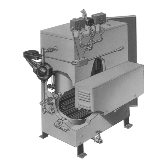
Type CES-6 through CES-180 Electric Steam Boiler
Boiler Serial Number . . . . . . . . . . . . . . . . . . . . . . . . . . . . . . . . Power Circuit Voltage . . . . . . . . . . . . . . . . . . . . . . . . . . . . . . . . . .
Model . . . . . . . . . . . . . . . . . . . . . . . . . . . . . . . . . . . . . . . . . . . Control Circuit Voltage . . . . . . . . . . . . . . . . . . . . . . . . . . . . . . . . .
National Board No. . . . . . . . . . . . . . . . . . . . . . . . . . . . . . . . . . Amps . . . . . . . . . . . . . . . Phase . . . . . . . . . . . Cy . . . . . . . . . .
Important — This data file contains the National Board Registration Certificate for your boiler. It must be kept near the boiler at all times.
© 2010 Chromalox, Inc.
Chromalox
Installation, Operation
and
Standard Trim is 100 PSI — 0-90 Operating Pressure Range
®
SERVICE REFERENCE
4
DIVISION
SALES
(Supersedes PQ444)
REFERENCE
MAY, 1999
DATE
Elec
Rating Cap.
Vol.
Model
(BHP) (kW) (Gals.) (Lbs./Hr.) 208
Type CES — 0-100 PSIG
CES-6
.6
6
6
CES-9
.9
9
6
CES-12
1.22
12
6
CES-18
1.73
17
6
CES-24
2.45
24
14.3
CES-30
2.95
29
14.3
CES-36
3.47
34
14.3
CES-48
4.69
46
14.3
CES-60
5.91
58
14.3
CES-72
6.93
68
14.3
CES-100
10.40 102
27.8
CES-135
13.9
136
30.5
CES-160
16.1 157.5 30.5
CES-180
18.4
180
30.5
* Single phase available up to and including 24 kW capacity.
† All boilers must have separate 120V Control Circuit or Transformer.
Boilers under 40 amps max are not fused.
CES
SECTION
PQ444-1
161-562789-002
3 Phase Voltages*
Output
No./kW
Quantity and Rating
at
of Contactors
212˚F
Heating
480† Elements
240
18
30
30
30
27
30
30
30
36.2
40
30
30
51.2
50
50
30
72.3
2-40
2-30
2-30
1-40
1-40
87.4
40
1-50
1-30
102.5
2-50
2-50
50
1-40
1-30
1-40
138.7
2-50
2-50
1-30
2-50
2-30
174.8
2-40
2-40
2-50
205
4-50
4-50
2-50
307
6-50
6-50
3-50
410
—
8-50
4-50
1-30
475
—
7-60
3-60
543
—
8-60
4-60
of
1-6
1-9
1-12
1-17
2-12
1-12
1-17
2-17
1-12
2-17
2-12
2-17
4-17
6-17
8-17
7-22.5
8-22.5
Advertisement
Table of Contents

Related Manuals for Chromalox CES-6


Summary of Contents for Chromalox CES-6
- Page 1 National Board No........Amps ....Phase ... Cy ..Important — This data file contains the National Board Registration Certificate for your boiler. It must be kept near the boiler at all times.
- Page 2 MODEL CES-6 through CES-18 Drain Blowdown Valve Pump/Solenoid Connection Conduit Box Element Access Door Element 5/8" 7/16" Bolt Hole (typical) MODEL CES-24 through CES-180 Drain Blowdown Valve Pump/Solenoid Connection Conduit Box Control Panel Standard when Three (3) or more Contactors are used 5/8"...
-
Page 3: Installation
Floor drain to be provided directly below unit. 9. All electrical wiring should be done by licensed electrician in accordance with national and local electrical codes. 10. If pump is located less than 30 feet from boiler, a second check valve is required. Heat... -
Page 4: Typical Wiring Diagrams
WARNING: Hazard of Electric Shock. Boiler must be suitably grounded according to N.E.C. standard. 1. Be sure to use the proper wire. Electric wiring to boiler should be in accordance with National Electrical Code or local wiring code following wiring diagram supplied. (See recommendations on safety switches and fusing.) - Page 5 Wire Color Code = Black BR = Brown = Red = Orange = Yellow = Green BL = Blue W = White Optional Transformer Boiler On Feed Water 1PS O Heater Contactors Optional Transformer Boiler On Feed Water 1PS O Heater...
- Page 6 = Orange = Yellow = Green BL = Blue W = White 3 HTR FU10 FU11 Optional Transformer X1 X3 X2 X4 Boiler On Feed Water 1PS O Heater Contactor Heater Contactor Optional Transformer Boiler On Feed Water 1PS O...
- Page 7 = Green BL = Blue W = White 3 HTR 4 HTR FU10 FU11 FU12 FU13 FU14 Optional Transformer Boiler On Feed Water 1PS O Heater Contactors 2 HTR 4 HTR Optional Transformer Boiler On Feed Water 1PS O Heater...
- Page 8 FU13 FU14 FU15 6 HTR FU16 FU17 FU18 FU10 FU11 FU12 FU19 FU20 Optional Transformer Boiler Feed Water Heater Contactor Heater Contactor Heater Contactor Heater Contactor Heater Contactor Heater Contactor L1 L2 L3 5 HTR 6 HTR FU10 FU11 Optional Transformer...
- Page 9 7 HTR FU13 FU20 FU21 FU10 6 HTR FU22 FU11 FU23 FU12 FU24 FU25 FU26 Optional Transformer Boiler Feed Water Heater Contactor Heater Contactor L1 L2 L3 5 HTR 6 HTR 7 HTR FU10 FU11 FU12 8 HTR FU14 FU13...
- Page 10 FU16 FU17 FU18 7 HTR FU19 FU20 FU21 FU10 FU11 FU12 FU22 FU23 Optional Transformer Boiler Feed Water Heater Contactor Heater Contactor Heater Contactor Heater Contactor Heater Contactor Heater Contactor Heater Contactor 5 HTR 6 HTR 7 HTR FU10 FU11...
-
Page 11: Pre-Operation Check
11 12 Cabinet Exterior Left Side Panel Layout After proper wiring and piping of boiler system is complete, testing of controls can start. Before testing controls, it is recommended that all contactor fusing be removed. This is to prevent possible element failure under test conditions. -
Page 12: Operation
ADJUSTING OPERATING PRESSURE CONTROLS 1. Chromalox boilers are supplied with operating and high limit pres- sure controls. One is used for controlling the operating pressure of the boiler while the other is used as a high limit control. To deter- mine the difference in the controls, the high limit has a manual reset lever on top of the case. -
Page 13: Automatic Blowdown Instructions
If the boiler is on 24-hour duty, set the OFF tab for the time that is desired for blowdown. the ON tab can be ignored, but must remain on timer. - Page 14 SCR and, in turn energize the control relay. As the water level in the boiler drops below the level of the probe, the AC current is broken and the control relay is de-energized. The control will not energize until sufficient water is present in the boiler.
- Page 15 Solid State Progressive Sequencer The solid state progressive sequencer provides accurate elec- tronic control of multi-stage loads of the type used in Chromalox steam boilers. It features progressive sequencing (first on-first off) which equalizes the operating time of each load. This control gives visual indication of each energized stage by means of integral solid state light emitting diodes.
-
Page 16: Condensate Return Systems
Range accordance with local and national electrical codes. Refer to boil- er instruction for manual wiring diagram. 0-100 psi 5. If pump is located less than 30 feet from boiler, a second check valve is required. Pump Motor Dimensions Assembly Model No. -
Page 17: Maintenance
Installation Wiring A. Check the voltage of the motor before making the wiring connec- tion. Some Chromalox boilers are supplied with dual voltage sys- tems. The motor should always match the voltage of the control circuit. B. The motor circuit should be wired into the pump control located on the boiler. - Page 18 Boiler 1" Steam Equalizing Pipe Pump and Low 1-1/2" Water Control Normal Boiler Water Level Cutoff Level is Arrow Mark Blowdown Valve 1" Water Equalizing Pipe 2-1/2 REF. FIG. 3 IMMERSION HEATER FAILURE CAUSES HEATER ELEMENT CONDITION 1. Water leakage at heater flange 2.
- Page 19 Pyrex Glass 2 “O” Ring Gaskets 7 3/4” CES-6 through CES-18 ......
-
Page 20: Limited Warranty
1/4” Ball Valve (Pressure Gauge) ......Blowdown Valve 1/2” CES-6 through CES-18 ....
Need help?
Do you have a question about the CES-6 and is the answer not in the manual?
Questions and answers