Table of Contents
Advertisement
Quick Links
Advertisement
Table of Contents

Related Manuals for PCB Piezotronics 8161-111A


Summary of Contents for PCB Piezotronics 8161-111A
- Page 1 Model 8161-111A STRAIN GAGE SENSOR SIGNAL CONDITIONER Installation and Operating Manual For assistance with the operation of this product, contact PCB Piezotronics, Inc. Toll-free: 800-828-8840 24-hour SensorLine: 716-684-0001 Fax: 716-684-0987 E-mail: info@pcb.com Web: www.pcb.com...
- Page 2 Assistance is needed to safely operate equipment PCB Piezotronics is an ISO-9001 certified company whose Damage is visible or suspected calibration services are accredited by A2LA to ISO/IEC Equipment fails or malfunctions 17025, with full traceability to SI through N.I.S.T.
- Page 3 CAUTION Refers to hazards that could damage the instrument. NOTE Indicates tips, recommendations and important information. The notes simplify processes and contain additional information on particular operating steps. The following symbols may be found on the equipment described in this manual: This symbol on the unit indicates that high voltage may be present.
- Page 4 PCB工业监视和测量设备 - 中国RoHS2公布表 PCB Industrial Monitoring and Measuring Equipment - China RoHS 2 Disclosure Table 有害物质 镉 汞 铅 (Pb) 六价铬 (Cr(VI)) 多溴联苯 (PBB) 多溴二苯醚 (PBDE) 部件名称 (Hg) (Cd) 住房 PCB板 电气连接器 压电晶体 环氧 铁氟龙 电子 厚膜基板 电线 电缆 塑料 焊接...
- Page 5 Component Name Hazardous Substances Lead (Pb) Mercury (Hg) Cadmium (Cd) Chromium VI Polybrominated Polybrominated Compounds Biphenyls (PBB) Diphenyl Ethers (Cr(VI)) (PBDE) Housing PCB Board Electrical Connectors Piezoelectric Crystals Epoxy Teflon Electronics Thick Film Substrate Wires Cables Plastic Solder Copper Alloy/Brass This table is prepared in accordance with the provisions of SJ/T 11364.
-
Page 6: Table Of Contents
8161 SERIES DIN RAIL AMPLIFIER MANUAL Table of Contents Section Page 1.0 Description 2.0 Power Connections 3.0 Transducer Cabling 4.0 Transducer Excitation 5.0 Calibration Resistor 6.0 Analog Outputs 7.0 Calibration Figures Figure Page Jumper Locations SW2 Switch Settings Transducer Hookup MANUAL NUMBER: 23708 MANUAL REVISION: E ECN NUMBER: 50103 (10/28/19) -
Page 7: Description
8161 SERIES DIN RAIL AMPLIFIER MANUAL 1.0 Description Series 8161 Signal Conditioner/Amplifier is designed for use with strain gage transducers that can operate with a DC excitation-amplification source. The 8161 series supplies either a 5 volt or a 10 volt transducer excitation, which can be selected through an internal jumper (see Figure The 8161 series contains all necessary balancing, gain, and calibration controls and conditions/amplifies the applied input to a standard +/-5 or +/- 10 volt (jumper selectable, see Figure 1), and 4-20 mA analog output. -
Page 8: Transducer Excitation
8161 SERIES DIN RAIL AMPLIFIER MANUAL 4.0 Transducer excitation Either 5 volt or 10 volt bridge excitation can be selected (see Figure 1). In general, 5-volt excitation is used with 120Ω transducers, and the 10-volt excitation is used with 350Ω and 700Ω transducers. -
Page 9: Sw2 Switch Settings
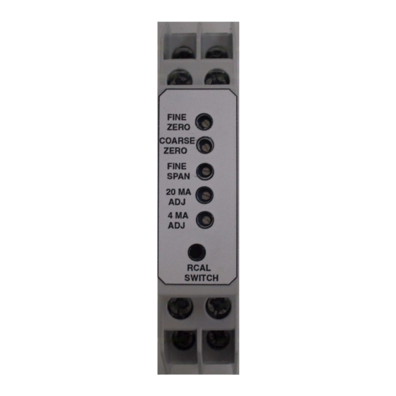
8161 SERIES DIN RAIL AMPLIFIER MANUAL “0” = Switch OFF, “1” = Switch ON Sensitivity (mV/V) Sensitivity (mV/V) SW2- for 5V for 10V 7.0 - 11.0 3.5 – 5.5 4.6 – 7.0 2.3 – 3.5 3.0 – 4.6 1.5 – 2.3 2.0 –... - Page 10 8161 SERIES DIN RAIL AMPLIFIER MANUAL reading previously recorded after dead weight calibration. If the current output is to be used, repeat the above step using the 20 mA adjust. 6. If dead weight calibration is not practical and the transducer manufacturer has supplied a calibration resistor (or resistor value), install the recommended calibration resistor.
-
Page 11: Transducer Hookup
8161 SERIES DIN RAIL AMPLIFIER MANUAL Sig (+) Sig (-) (4-20 mA) Ground Return = 10-28 VDC SUPPLY Ground (10-28 VDC) supply (4-20 mA) (±5 or ±10 V) - Excitation + Excitation - Signal +Signal Figure 3– Transducer Hook-up...
Need help?
Do you have a question about the 8161-111A and is the answer not in the manual?
Questions and answers