
Subscribe to Our Youtube Channel
Related Manuals for Velleman WSI8004


Summary of Contents for Velleman WSI8004
- Page 1 Total solder points: 82 Difficulty level: beginner 1 2 3 4 5 advanced Dc to Pulse Width Modulator K8004 ILLUSTRATED ASSEMBLY MANUAL H8004IP-2...
- Page 2 Features & Specifications Features: PWM range: 0 to 100%. PWM frequency: 100 to 5000Hz adjustable. Minimum PWM offset: 0 to 20% adjustable. Adjustable sensitivity: 2.5 to 35VDC Short circuit protection. Overload protection: 6.5A Specifications: Power Supply: 8 to 35VDC unregulated Supply current (No load): 35mA typ Efficiency: better than 90% at full load...
- Page 3 Assembly hints 1. Assembly (Skipping this can lead to troubles ! ) Ok, so we have your attention. These hints will help you to make this project successful. Read them carefully. 1.1 Make sure you have the right tools: A good quality soldering iron (25-40W) with a small tip.
- Page 4 Assembly hints 1.3 Soldering Hints : 1- Mount the component against the PCB surface and carefully solder the leads 2- Make sure the solder joints are cone-shaped and shiny 3- Trim excess leads as close as possible to the solder joint REMOVE THEM FROM THE TAPE ONE AT A TIME ! DO NOT BLINDLY FOLLOW THE ORDER OF THE COMPONENTS ONTO THE TAPE.
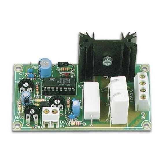
- Page 5 Construction 3. IC socket. Watch the posi- 1. Diodes. Watch the polarity ! 5. PCB pins tion of the notch! D... CATHODE D1 : 1N4148 D2 : 1N4148 IC1 : 16P Vref D3 : 1N4007 2.
- Page 6 Construction 7. Transistor 10. Screw connectors 12. Transistor T1 : BC547 J1 : 2p 10mm M3 BOLT LOCK WASHER 8. Electrolytic capacitor. J2 : 2p Watch the polarity ! J3 : 2p T2 : BUK9535-55 or eq. ...
- Page 7 Test 14. Test Connect the supplied 4k7 resistor between the + and - points of the load. Connect the Vref point to the DC input. Set preset RV3 to the middle of its adjustment range. Connect a DC voltage between 8 and 35V with the points +V and GND. ...
-
Page 8: Different Configurations
Different configurations 15. Different configurations K8004 Figure A : DC LOAD POWER SUPPLY LOAD (8...35VDC) Standard configuration, use a separate control voltage. DCIN DC CONTROL VOLTAGE (max. 35V) Figure B : K8004 LOAD POWER SUPPLY LOAD Connection to one of the analogue outputs of the K8000 interface card. If (8...35VDC) DAC1 is used then the circuit can be controlled with the demo program, DCIN... - Page 9 Setting up 16. Setting up RV1: setting the minimum output voltage. Set the control voltage to zero (perhaps by disconnecting it). An initial pre-voltage can then be adjusted using preset RV1. This is especially useful with motors (in order to overcome mechanical resistance) and with halogen lamps (in order to pre-heat the filament).
- Page 10 17. PCB P8004'2...
- Page 11 Schematic diagram 18. Schematic diagram.
- Page 12 VELLEMAN NV Legen Heirweg 33, B-9890 GAVERE Belgium (Europe) Modifications and typographical errors reserved © Velleman nv. H8004IP’2 (rev.4.0) 5 4 1 0 3 2 9 2 9 2 0 9 6...
Need help?
Do you have a question about the WSI8004 and is the answer not in the manual?
Questions and answers