
Related Manuals for Velleman K8004


Summary of Contents for Velleman K8004
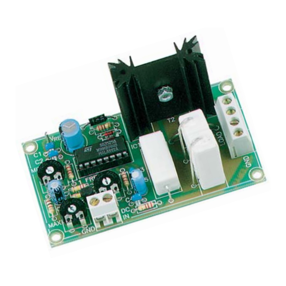
- Page 1 Total solder points: 82 Difficulty level: beginner 1 advanced Dc to Pulse Width Modulator K8004 ILLUSTRATED ASSEMBLY MANUAL H8004IP-2...
-
Page 2: Specifications
Features & Specifications Features: PWM range: 0 to 100%. PWM frequency: 100 to 5000Hz adjustable. Minimum PWM offset: 0 to 20% adjustable. Adjustable sensitivity: 2.5 to 35VDC Short circuit protection. Overload protection: 6.5A Specifications: Power Supply: 8 to 35VDC unregulated Supply current (No load): 35mA typ Efficiency: better than 90% at full load Dimensions (wxdxh): 85 x 48 x 45mm... - Page 3 Assembly hints 1. Assembly (Skipping this can lead to troubles ! ) Ok, so we have your attention. These hints will help you to make this project successful. Read them carefully. 1.1 Make sure you have the right tools: • A good quality soldering iron (25-40W) with a small tip.
- Page 4 Assembly hints 1.3 Soldering Hints : 1- Mount the component against the PCB surface and carefully solder the leads 2- Make sure the solder joints are cone-shaped and shiny 3- Trim excess leads as close as possible to the solder joint REMOVE THEM FROM THE TAPE ONE AT A TIME ! AXIAL COMPONENTS ARE TAPED IN THE COR- RECT MOUNTING SEQUENCE !
- Page 5 Construction 3. IC socket. Watch the posi- 1. Diodes. Watch the polarity ! 5. PCB pins tion of the notch! D... CATHODE D1 : 1N4148 D2 : 1N4148 IC1 : 16P Vref D3 : 1N4007 2. Resistors 4. Trim potentiometer 6.
- Page 6 Construction 7. Transistor 10. Screw connectors 12. Transistor T1 : BC547 J1 : 2p 10mm M3 BOLT LOCK WASHER 8. Electrolytic capacitor. J2 : 2p Watch the polarity ! J3 : 2p T2 : BUK9535-55 or eq. C5 : 10µ F C...
- Page 7 Test 14. Test Connect the supplied 4k7 resistor between the + and - points of the load. Connect the Vref point to the DC input. Set preset RV3 to the middle of its adjustment range. Connect a DC voltage between 8 and 35V with the points +V and GND. Measure between the + and - points of LOAD with a voltmeter (set to read DC voltage).
-
Page 8: Different Configurations
Different configurations 15. Different configurations K8004 Figure A : DC LOAD POWER SUPPLY LOAD (8...35VDC) Standard configuration, use a separate control voltage. DCIN DC CONTROL VOLTAGE (max. 35V) Figure B : K8004 LOAD POWER SUPPLY LOAD Connection to one of the analogue outputs of the K8000 interface card. If (8...35VDC) - Page 9 Setting up 16. Setting up RV1: setting the minimum output voltage. Set the control voltage to zero (perhaps by disconnecting it). An initial pre-voltage can then be adjusted using preset RV1. This is especially useful with motors (in order to overcome mechanical resistance) and with halogen lamps (in order to pre-heat the filament).
- Page 10 17. PCB P8004'2...
- Page 11 Schematic diagram 18. Schematic diagram.
- Page 12 VELLEMAN Components NV Legen Heirweg 33 9890 Gavere Belgium Europe www.velleman.be www.velleman-kit.com Modifications and typographical errors reserved © Velleman Components nv. H8004IP - 2003 - ED3 5 4 1 0 3 2 9 2 9 2 0 9 6...
Need help?
Do you have a question about the K8004 and is the answer not in the manual?
Questions and answers