
Subscribe to Our Youtube Channel
Related Manuals for ESD electronic PowerPC EPPC-405-1

Summary of Contents for ESD electronic PowerPC EPPC-405-1
- Page 1 EPPC-405 Embedded PowerPC with CAN and ETHERNET Hardware Manual EPPC-405 Hardware Manual Rev. 1.2...
- Page 2 I:\texte\Doku\MANUALS\Embedded\EPPC-405\EPPC_12H.en9 Document file: Date of print: 02.08.2001 Changes in the chapters The changes in the document affect changes in the hardware as well as descriptions of facts only. Chapter Changes versus previous version Pin assignment of power connector has changed! Technical details are subject to change without notice.
- Page 3 Vahrenwalder Str. 207 30165 Hannover Germany...
-
Page 4: Table Of Contents
Contents 1. Overview ..............3 1.1 Description of the EPPC-405-Computer . - Page 5 This page is intentionally left blank. EPPC-405 Hardware Manual Rev. 1.2...
-
Page 6: Overview
Overview 1. Overview 1.1 Description of the EPPC-405-Computer electrical isolation Power Supply Physical IDE- Combicon- CAN0 CAN Controller 3,3 V DSUB9 CompactFlash Style NVRAM SJA1000 CAN0 Power Supply Layer Interface 24 V +5 V= DC/DC Converter CAN1 CAN Controller FPGA 10/100BaseT RJ45 +5 V=... -
Page 7: Front Panel View With Connector Assignment
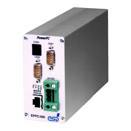
Overview 1.2 Front Panel View with Connector Assignment Alternative: RS-232 Interface SER0 Order-No. I.2001.02: RS-232 Interface SER1 Order-No. I.2001.03: CAN Interface CAN1 CAN Interface CAN0 LED Display Power Supply 24VDC Ethernet 10/100BaseT EPPC/405 Fig. 1.2.1: Front panel view EPPC-405 Hardware Manual Rev. 1.2... - Page 8 Overview 1.3 Dimensions for Installation 20 mm 72,5 mm 184 mm 55 mm 4 mm 105 mm 20 mm EPPC-405 55 mm Fig. 1.3.1: Dimensions of the EPPC-405 for installation EPPC-405 Hardware Manual Rev. 1.2...
-
Page 9: Summary Of Technical Data
Overview 1.4 Summary of Technical Data 1.4.1 General Technical Data Ambient temperature 0...50°C Humidity max. 90 %, non-condensing SER0 (6-pin RJ11-female) - RS-232 interface (Serial 0) CAN0 (9-pin DSUB-male) - CAN 0 (ISO11898) Ethernet (8-pin RJ45-female) - ETHERNET Twisted 10/100 Pair (IEEE 802.3) Connectors Power... -
Page 10: Serial Interface 1 (Only Order No. I.2001.02)
Overview 1.4.3 Serial Interface 1 (only Order No. I.2001.02) Drive PPC405GP micro controller: 1200 bit/s ... 312. 500 kbit/s Bit rate RS-232 transceiver: max. 38.4 kbit/s Physical interface RS-232C Connector 9-pin DSUB-female in front panel Table 1.4.3: Serial interface 1 1.4.4 CAN-Interface 1 (only Order No. -
Page 11: Order Information
Overview 1.4.5 Order Information Type Features Order No. EPPC-405 IBM PPC405GP, 200 MHz, 16 MB SDRAM, 4 I.2001.02 MB Flash, 2x RS-232, 1x CAN IBM PPC405GP, 200 MHz, 16 MB SDRAM, 4 I.2001.03 MB Flash, 1x RS-232, 2x CAN EPPC-405-ME English manual I.2001.21 *) If manual and product are ordered together, the manual is free of charge. -
Page 12: Connector Assignment
Connector Assignment 2. Connector Assignment For the assignment of connectors for serial interface 0, CAN-interface 0 and the Ethernet interface please refer to the CPCI-405 manual. In this chapter only the connectors will be described which are not on the CPCI-405 board. 2.1 Serial Interface 1 (SER1) Pin Position: Pin Assignment:... -
Page 13: Can-Bus Interface 1
Connector Assignment 2.2 CAN-Bus Interface 1 (CAN 1) Pin Position: Pin Assignment: Signal Signal reserved CAN_GND CAN_L CAN_H CAN_GND reserved reserved reserved shield 9-pin female DSUB Signal Description: CAN_L, CAN_H ... CAN-signal lines CAN_GND ... reference potential of the local CAN-physical layer shield ... - Page 14 Connector Assignment 2.3 Power Supply Shield +24 VDC EPPC/405 EPPC-405 Hardware Manual Rev. 1.2...
- Page 15 CPCI-405 Page 1 of 57 Hardware-Manual • Doc.-No.: I.2306.21 / Rev. 3.5 esd electronic system design gmbh Vahrenwalder Str. 207 • 30165 Hannover • Germany http://www.esd.eu Phone: +49 (0) 511 3 72 98-0 • Fax: +49 (0) 511 3 72 98-68...
- Page 16 All rights to this documentation are reserved by esd. Distribution to third parties and reproduction of this document in any form, whole or in part, are subject to esd’s written approval. © 2015 esd electronics system design gmbh, Hannover esd electronic system design gmbh Vahrenwalder Str. 207 30165 Hannover...
- Page 17 Document file: I:\Texte\Doku\MANUALS\CPCI\CPCI405\Englisch\CPCI-405_Hardware_en_35.wpd 2015-11-13 Date of print: Serial Number: from BC882 Changes in the chapters The changes in the document listed below affect changes in the hardware as well as changes in the description of the facts, only. Version Chapter Changes as compared with previous version 1.3.3 NVRAM specified...
- Page 18 Safety Instructions When working with CPCI-405 modules follow the instructions below and read the manual carefully to protect yourself and the CPCI-405 module from damage. The device is a built-in component. It is essential to ensure that the device is mounted in a way that cannot lead to endangering or injury of persons or damage to objects.
-
Page 19: Dimensions For Installation
normal function, get illegal access or cause damage. esd does not take responsibility for any damage caused by the device if operated at any networks. It is the responsibility of the device's user to take care that necessary safety precautions for the device's network interface are in place. - Page 20 Contents Page 1. Overview ..............8 1.1 Description of the CPCI-405 Board .
- Page 21 5.2 CPCI-405-A PCI-Adapter with 6 U Front Panel (I.2306.47) ......39 5.2.1 Front Panel view of the CPCI-405-A PCI-Adapter with 6 U Front Panel ..40 5.3 Serial Interface .
-
Page 22: Overview
Overview 1. Overview 1.1 Description of the CPCI-405 Board Fig. 1.1.1: Block circuit diagram The CPCI-405 is a CompactPCI board in Euro format. It is available as PCI-master CPU or as intelligent slave board. Both options only differ in the configuration of the PowerPC 405GPr processor. Apart from a powerful CPU the PowerPC 405GPr processor has got an SDRAM controller, a PCI-bus interface, a controller for serial interfaces and an MII-interface which is here used to realize an ETHERNET interface. - Page 23 Overview The TTL-signals of both controllers are led to a post connector. Here, two adapter boards can be connected via flat ribbon cables, realising the physical layer. The adapter boards are available with CAN (ISO11898) or DeviceNet interfaces. Optionally the CPCI-405 together with the adapter board is available in two special designs (page 37).
-
Page 24: Pcb View With Connector Designations
Overview 1.2 PCB View with Connector Designations Fig. 1.2.1: PCB view (diagram without front panel) The connector pin assignments can be found on page 25 and the following. Page 10 of 57 CPCI-405 Hardware-Manual • Doc.-No.: I.2306.21 / Rev. 3.5... -
Page 25: Power Supply
Overview 1.3 Summary of Technical Data 1.3.1 General Technical Data Ambient temperature 0...50 C Humidity max. 90 %, non-condensing via CompactPCI-bus, 5 V ± 5% / 200 mA (from PCB-rev. 2.0 on) Power supply 3.3 V ± 5% / 800 mA (from PCB-rev. 2.0 on) X100 (132-pin post connector) - CompactPCI-board connector J1 X101 (132-pin post connector) - CompactPCI-board connector J2 X700 (6-pin RJ12-socket) - RS-232-interface (SER 0) -
Page 26: Compactpci Bus
Overview 1.3.2 CompactPCI Bus Host bus PCI-bus in accordance with PCI Local Bus Specification 2.2 PCI-data/address bus 32 bits Controller PowerPC 405GPr Interrupt interrupt signal A, B, C, D Board dimension in accordance with PCI-Specification, Rev. 1.0 Connectors Universal Board, not keyed Connector coding (3,3 V or 5 V signalling voltage) Table 1.3.2: CompactPCI Bus interface... -
Page 27: Serial Interfaces
Overview 1.3.4 Serial Interfaces Number Controller PowerPC 405GPr Microcontroller: 300 bit/s ... 115.200 bit/s Bit rate RS-232-Transceiver: max. 115.200 Kbit/s Serial 0: RS-232C Physical interface Serial 1: TTL-level signals Serial 0: 6-pin RJ12-socket in front panel Connectors Serial 1: 6-pin post connector on board Table 1.3.4: Serial interfaces 1.3.5 CAN-Interfaces Number... -
Page 28: Ethernet Interface
Overview 1.3.6 ETHERNET Interface Number Bit rate 10 Mbit/s, 100 Mbit/s Controller PowerPC405GPr Physical interface Twisted Pair (IEEE 802.3) 10/100BASE-T Electrical insulation via repeating coil Connector 8-pin RJ45-socket in front panel Table 1.3.6: ETHERNET interface 1.3.7 CompactFlash Card Interface Information about Usage of CompactFlash® Cards! A correct functionality of the CompactFlash interface can only be ensured by usage of CompactFlash cards with guaranteed SSD-properties. -
Page 29: Front Panel View With Led-Display
LED-Display 2. Front Panel View with LED-Display The module has got four LEDs in the front panel and another LED which can only be seen on the board itself when the case is open. 2.1 LEDs in the Front Panel Fig. - Page 30 LED-Display Name Colour Meaning of LED when on CAN-frames are being received or transmitted green The LED is hardwired. The LED cannnot be controlled through software. local CPU is in RUN status (LED lights at every access to the SDRAM, therefore the LED can be green blinking or permanently on in normal operation) The LED is hardwired.
-
Page 31: Powerpc Microcontroller Ppc405Gpr
Description of Units 3. Description of Units 3.1 PowerPC Microcontroller PPC405GPr 3.1.1 General The general functions of the PowerPC 405GPr will not be explained in this manual. The manual of the microcontroller can be downloaded from the homepage of the manufacturer AMCC at: CPCI-405 Page 17 of 57 Hardware-Manual •... -
Page 32: Address Assignment
Description of Units 3.1.2 Address Assignment Start address End address Unit [HEX] [HEX] SDRAM (max. 64 Mbyte) PCI Core memory Internal periphery: UART0-register (see 405GP-Manual Table 3-6 , S. 3-9) * UART1-register (see 405GP-Manual Table 3-7 , S. 3-10) * IIC0-register (see 405GP-Manual Table 3-8 , S. -
Page 33: Interrupt Settings
Description of Units 3.1.3 Interrupt Settings Interrupt External IRQ Circuit Level Detection IRQ 25 EXT IRQ 0 CAN0 low active, level sensitive IRQ 26 EXT IRQ 1 CAN1 low active, level sensitive IRQ 27 EXT IRQ 2 PCI-INT_A high active, level sensitive IRQ 28 EXT IRQ 3 PCI-INT_B... -
Page 34: Serial Interface
Description of Units 3.2 Serial Interface 3.2.1 Default Setting The default setting for both serial interfaces is the following: Bit rate: 9600 Baud Data bits: Parity: Stop bits: Handshake: none 3.2.2 Configuration The serial interfaces are controlled by the microcontroller PowerPC405GPr. The bit rate of the interfaces can be configured. -
Page 35: Connecting The Rs-232-Interface Ser 0
Description of Units 3.2.3 Connecting the RS-232-Interface SER 0 The diagram is used to explain the short terms for signals as used in the chapter (Connector Assignments). The signal terms are exemplary for the connection of the CPCI-405 as a modem (DCE) via the adapter cable RJ12-DSUB9. -
Page 36: Function Of Coding Switch
Description of Units 3.3 Function of Coding Switch 3.3.1 Overview Coding switch Function Default setting at delivery no special function / general purpose no special function / general purpose no special function / general purpose switching the boot Flash-EPROM boot from Flash-EPROM U600 Table 3.3.1: Assignment of coding switch bits The state of the DIP switches can be read at address 0xF040 0002. -
Page 37: Can/Devicenet Unit
Description of Units 3.4 CAN/DeviceNet Unit 3.4.1 General The CPCI-405 has got two independent CAN-channels. Each of these CAN-channels has got its own SJA1000 controller. CAN-channel CAN0 can be accessed via 9-pin DSUB connector X1000 in the front panel. An 82C250/82C251 is used as driver unit. -
Page 38: Interface Circuits
Description of Units 3.4.2 Interface Circuits The following diagram represents the principal circuit of the CAN-interface. The local CAN-interface of CAN0 is identically constructed to the CAN-interface on the adapter board. Fig. 3.4.1: Circuit of CAN-interface Fig. 3.4.2: Circuit of the DeviceNet interface on the adapter board Page 24 of 57 CPCI-405 Hardware-Manual •... -
Page 39: Connector Assignment
Connector Assignment 4. Connector Assignment 4.1 Serial Interfaces For details on the connection of serial interfaces please refer also to chapter ‘Serial Interfaces’ on page 20. From the principle circuit diagrams represented in that chapter, you will be able to clearly determine the signal direction (Rx <->... -
Page 40: Ser 0: Connection Cable Rj12-Dsub9
Connector Assignment 4.1.2 SER 0: Connection Cable RJ12-DSUB9 1,5 m RJ12 (6P6C), DSUB female 6-Pol. 9-pole CPCI-405 local signal names used at CPCI-405 Page 26 of 57 CPCI-405 Hardware-Manual • Doc.-No.: I.2306.21 / Rev. 3.5... -
Page 41: Ser 0: Dsub-Socket When Using The Adapter Cable Rj12-Dsub9
Connector Assignment 4.1.3 SER 0: DSUB-Socket when Using the Adapter Cable RJ12-DSUB9 Pin Position: Pin Assignment: Signal Signal n.c. n.c. RxD-S0 (output) RTS-S0 (input) TxD-S0 (input) CTS-S0 (output) n.c. n.c. 9-pin DSUB female n.c..not connected The names of the signals are specified as seen from the terminal (PC). The signal direction specified in brackets is shown as seen from the CPCI-405 board. -
Page 42: Ser 1: Assignment Of The 6-Pin Post Connector X710
Connector Assignment 4.1.4 SER 1: Assignment of the 6-pin Post Connector X710 The signals of the serial interface SER 1 at X710 have TTL-Level! Signal Connector pin Signal +5 V TxD-S1/STR17 RTS-S1/STR18 Attention: The signals at the pins 3 and 6 will not only be used as TxD- and RxD-Signals. In the boot sequence of the PowerPC 405 these signals are used to define the setting of the operation mode (Strapping Pins). -
Page 43: Can-Bus Interface (X1000)
Connector Assignment 4.2 CAN-Bus Interface (X1000) The position of the signals in the DSUB-connector of CAN-channel CAN0 (X1000) in the front panel, and the DSUB-connector on the optional adapter board are identical. Pin Position: Pin Assignment: Signal Signal reserved CAN0_GND CAN0_L CAN0_H CAN0_GND... -
Page 44: Can-Ttl Signals (X1010)
Connector Assignment 4.3 CAN-TTL Signals (X1010) Connector X1010 has been assigned with the Rx/Tx-signals of both CAN-controllers. The signals are on TTL-level and are not electrically insulated from the microcontroller units! X1010 has been designed for the connection of the optional adapter boards to the physical layer for CAN or DeviceNet. -
Page 45: Option: Devicenet-Adapter Boards
Connector Assignment 4.4 Option: DeviceNet-Adapter Boards Both CAN-channels can be connected to two adapter boards by means of connector X1010. When using the DeviceNet option the adapter boards are equipped with Phoenix-Combicon connectors MSTB 2.5/- GF-5.08 (or equal). The DeviceNet interface has been constructed in accordance with the ‘DeviceNet Communication Model and Protocol, Rel. - Page 46 Connector Assignment The DeviceNet option includes the CPCI-405, the DeviceNet-adapter board, the flat ribbon cable, the fastening angles and all screws, nuts and securing plates required. Fig. 4.3.1: Wiring of adapter boards The dimensions specified in the following diagrams are in millimetres. 36,0 27,8 20,5...
- Page 47 Connector Assignment 40,0 Fig. 4.3.4: Recommended space at the external Fig. 4.3.5: Recommended space at the external case wall for adapter boards with case wall for adapter boards with DeviceNet connector DSUB9 connector (considers for instance the following Phoenix Combicon connector groups: MSTB, MSTBP, MVSTBR, MVSTBW, TMSTBP)
-
Page 48: Ethernet 10/100Base-T Connection (X1200)
Connector Assignment 4.5 ETHERNET 10/100BASE-T Connection (X1200) Pin Position: Cut-out for fastening lever Pin Assignment: Signal TP01 (TxD+) TP02 (TxD-) TP03 (RxD+) TP04 TP05 TP06 (RxD-) TP07 TP08 8-pin RJ45-socket Permissible cable types: Cables of category 5e or higher have to be used to grant the function in networks with up to 100 Mbits/s. -
Page 49: Debug Port X720
Connector Assignment 4.6 Debug Port X720 With the debug port e.g. firmware updates can be executed. It can be connected via a SMD-pin contact strip connector. It is recommended to build a simple adapter from the SMD-pin contact strip connector to a 16-pin post connector to connect the port. -
Page 50: Signal Alignment Of 8-Pole Smd-Strip And Jtag-Adapter (From Pcb-Rev. 2.X)
Connector Assignment 4.6.2 Signal Alignment of 8-pole SMD-Strip and JTAG-Adapter (from PCB-Rev. 2.x) JTAG Connector to X720 16-pole Post Connector 8-pole SMD-Strip n.c. TRST* 10k Pull-Up to 3.3V n.c. TMS0 HALT n.c. n.c. n.c. n.c. Example of an n.c. Adapter (Uncasted) Connectors to build adapter: SMD-pin contact strip: Fa. -
Page 51: Special Designs: Cpci-405 With Cpci-Can-Iso11898 Add-On
Special Designs with CPCI-CAN-ISO11898 Add-On 5. Special Designs: CPCI-405 with CPCI-CAN-ISO11898 Add-On In the special designs the add-on CPCI-CAN-ISO11898 (I.2301.03) is already integrated in the CPCI-405 module which comes with a 8 HP front panel (I.2306.49, I.2306.12) or a 6 U front panel (I.2306.47). -
Page 52: Front Panel View Of Cpci-405-2 With Adapter Board And 8 Hp Front Panel
Special Designs with CPCI-CAN-ISO11898 Add-On 5.1.1 Front Panel view of CPCI-405-2 with Adapter Board and 8 HP Front Panel The assignment and display function of the LEDs and the position and assignment of connector X700, X1000 and X1200 are the same as described for the CPCI-405. CPCI-405 Fig. -
Page 53: Cpci-405-A Pci-Adapter With 6 U Front Panel (I.2306.47)
Special Designs with CPCI-CAN-ISO11898 Add-On 5.2 CPCI-405-A PCI-Adapter with 6 U Front Panel (I.2306.47) In this design the adapter board CPCI-CAN-ISO11898 is connected to the CPCI-405 via ribbon cable. (Fig. shows CPCI-405-A-design up to S/N BC882) Fig. 5.2.1: CPCI-405-A PCI-adapter with adapter board and 6 U front panel CPCI-405 Page 39 of 57 Hardware-Manual •... -
Page 54: Front Panel View Of The Cpci-405-A Pci-Adapter With 6 U Front Panel
Special Designs with CPCI-CAN-ISO11898 Add-On 5.2.1 Front Panel view of the CPCI-405-A PCI-Adapter with 6 U Front Panel The assignment and display function of the LEDs and the position and assignment of connector X700, X1000 and X1200 are the same as described for the CPCI-405. Fig. -
Page 55: Serial Interface
Special Designs with CPCI-CAN-ISO11898 Add-On 5.3 Serial Interface The serial Interface SER1 is per default configured for RS-232 operation. The interface can be configured as RS-422 or RS-485 interface via the solder bridges LB100 - LB103 (page 43). The following figures explain the code designation of the signals used in the connector assignments. 5.3.1 RS-232 Interface The Figure exemplifies the connection of the CPCI-405 via the adapter cable RJ12 <->... -
Page 56: Rs-485 Interface
Special Designs with CPCI-CAN-ISO11898 Add-On 5.3.3 RS-485 interface Fig. 5.3.3: Connection scheme for RS-485 operation For the RS-485 interface the data direction (receive/transmit) of the driver component has to be switched by software. The data direction can be switched with the RTS-signal, which is connected with the data enable (DE) of the driver component. -
Page 57: Solder Bridges For The Configuration Of The Serial Interface Ser1
Special Designs with CPCI-CAN-ISO11898 Add-On 5.3.4 Solder Bridges for the Configuration of the Serial Interface SER1 The serial interface SER1 can be configured with the solder bridges LB100 - LB103. P200 Fig. 5.3.5: Position of the solder bridges on the board (detail drawing) Configuration of the serial interface SER1 with the solder bridges LB100-LB102: solder RS-232... -
Page 58: Connector Assignments Of The Special Designs
Special Designs with CPCI-CAN-ISO11898 Add-On 5.4 Connector Assignments of the Special Designs 5.4.1 CAN-Interface CAN 1 Pin Position: Pin Assignment: Signal Signal reserved CAN1_GND CAN1_L CAN1_H CAN1_GND reserved reserved reserved Shield 9-pin DSUB connector Signal Description: CAN1_L, CAN1_H... CAN-signal lines (generated from the CAN-Controller TTL-signals Tx0- CAN1* and Rx0-CAN1*) CAN1_GND ... -
Page 59: Ser1: Assignment Of The Rj12 Socket P100
Special Designs with CPCI-CAN-ISO11898 Add-On 5.4.2 SER1: Assignment of the RJ12 Socket P100 The serial interface SER1 of the adapter board can be configured as RS-232, RS-422 or RS-485 interface. The configuration via the solder bridges is described in the previous chapter (see page 43). For notes on the connection of serial interfaces please refer to chapter ‘Serial Interfaces’... -
Page 60: Correct Wiring Of Electrically Isolated Can Networks
Wiring Notes 6. Correct Wiring of Electrically Isolated CAN Networks For the CAN wiring all applicable rules and regulations (EU, DIN), e.g. regarding electromagnetic compatibility, security distances, cable cross-section or material, have to be met. 6.1 Standards concerning CAN Wiring The flexibility in CAN network design is one of the key strengths of the various extensions and additional standards like e.g. -
Page 61: Heavy Industrial Environment (Double Twisted Pair Cable)
Wiring Notes 6.2 Heavy Industrial Environment (Double Twisted Pair Cable) 6.2.1 General Rules Note: esd only grants the compliance with directive 2014/30/EC, if the CAN wiring is carried out with single shielded double twisted pair cables that match the requirements of ISO 11898-2. -
Page 62: Device Cabling
Wiring Notes 6.2.2 Device Cabling Attention: If single shielded double twisted pair cables are used, realize the T-connections by means of connectors that support connection of two CAN cables at one connector where the cable’s shield is looped through e.g. DSUB9-connector from ERNI (ERBIC CAN BUS MAX, order no.:154039). -
Page 63: Light Industrial Environment (Single Twisted Pair Cable)
Wiring Notes 6.3 Light Industrial Environment (Single Twisted Pair Cable) 6.3.1 General Rules Note: esd only grants the compliance with directive 2004/30/EC, if the CAN wiring is carried out with single shielded double twisted pair cables that match the requirements of ISO 11898-2. -
Page 64: Cabling
Wiring Notes 6.3.2 Cabling To connect CAN devices with just one CAN connector per net use a short stub (< 0.3 m) and a T-connector (available as accessory). If this devices are located at the end of the CAN network, the CAN terminator “CAN-Termination-DSUB9”... -
Page 65: Electrical Grounding
Wiring Notes 6.4 Electrical Grounding For CAN devices with electrical isolation the CAN_GND must be connected between the CAN devices. CAN_GND should be connected to the earth potential (FE) at exactly one point of the network. Each CAN interface with electrical connection to earth potential acts as grounding point. For this reason it is recommended not to connect more than one CAN device with electrical connection to earth potential. -
Page 66: Examples For Can Cables
Wiring Notes 6.6 Examples for CAN Cables esd recommends the following two-wire and four-wire cable types for CAN network design. These cable types are used by esd for ready-made CAN cables, too. 6.6.1 Cable for Light Industrial Environment Applications (Two-Wire) Manufacturer Cable Type e.g. -
Page 67: Can-Bus Troubleshooting Guide
CAN-Bus Troubleshooting Guide 7. CAN-Bus Troubleshooting Guide The CAN Troubleshooting Guide is a guide to find and eliminate the most frequent hardware-error causes in the wiring of CAN networks. Figure. 6: Simplified diagram of a CAN network 7.1 Termination The termination is used to match the impedance of a node to the impedance of the transmission line being used. -
Page 68: Electrical Grounding
CAN-Bus Troubleshooting Guide 7.2 Electrical Grounding CAN_GND of the CAN network should be connected to Functional earth potential (FE) at only one point. This test will check if the CAN_GND is grounded in several places. To test it, please 1. Disconnect the CAN_GND from the earth potential (FE). -
Page 69: Can Transceiver Resistance Test
CAN-Bus Troubleshooting Guide If it is lower than 2.0 V or higher than 3.0 V, it is possible that one or more nodes have faulty transceivers. For a voltage lower than 2.0 V please check CAN_H and CAN_L conductors for continuity. -
Page 70: Eu Declaration Of Conformity
Declaration of Conformity 8. EU Declaration of Conformity Page 56 of 57 CPCI-405 Hardware-Manual • Doc.-No.: I.2306.21 / Rev. 3.5... -
Page 71: Order Information
Order Information 9. Order Information Type Features Order No. AMCC PowerPC405GPr, 266 MHz, 64 MB SDRAM, CPCI-405 I.2306.04 4 MB Flash, CPCI-host CPCI-405-64 as I.2306.04, but AMCC PowerPC405GPr with 400 MHz I.2306.05 as I.2306.04, but CPCI-target adapter I.2306.07 CPCI-405-A as I.2306.07, but with 4 HP / 6 U front panel I.2306.47 CPCI-405-A-64 as I.2306.05, but CPCI-target adapter...
Need help?
Do you have a question about the PowerPC EPPC-405-1 and is the answer not in the manual?
Questions and answers