Table of Contents
Advertisement
Quick Links
Safe Operation Practices • Set-Up • Operation • Maintenance • Service • Troubleshooting • Warranty
OPERATOR'S MANUAL
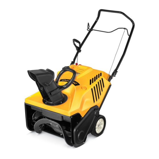
Single-Stage Snow Thrower — 2S5 Series
WARNING
READ AND FOLLOW ALL SAFETY RULES AND INSTRUCTIONS IN THIS MANUAL
BEFORE ATTEMPTING TO OPERATE THIS MACHINE.
FAILURE TO COMPLY WITH THESE INSTRUCTIONS MAY RESULT IN PERSONAL INJURY.
P. O. Box 1386, 97 KENT AVENUE, KITCHENER, ON N2G 4J1
Printed In USA
769-07155
05.17.11
Advertisement
Table of Contents

Subscribe to Our Youtube Channel
Related Manuals for Cub Cadet 2S5 Series


Summary of Contents for Cub Cadet 2S5 Series
- Page 1 Safe Operation Practices • Set-Up • Operation • Maintenance • Service • Troubleshooting • Warranty OPERATOR’S MANUAL Single-Stage Snow Thrower — 2S5 Series WARNING READ AND FOLLOW ALL SAFETY RULES AND INSTRUCTIONS IN THIS MANUAL BEFORE ATTEMPTING TO OPERATE THIS MACHINE.
-
Page 2: Table Of Contents
Choose from the options below: ◊ Visit our web at www.cubcadet.ca ◊ Locate your nearest dealer from Customer Support: 1-800-668-1238 ◊ Contact Cub Cadet • P.O. Box 1386 • 97 Kent Avenue • Kitchener, Ontario, Canada • N2G 4J1... -
Page 3: Safe Operation Practices
Important Safe Operation Practices WARNING! This symbol points out important safety instructions which, if not followed, could endanger the personal safety and/or property of yourself and others. Read and follow all instructions in this manual before attempting to operate this machine. Failure to comply with these instructions may result in personal injury. - Page 4 Safe Handling of Gasoline Never run an engine indoors or in a poorly ventilated area. Engine exhaust contains carbon monoxide, an odorless To avoid personal injury or property damage use extreme care and deadly gas. in handling gasoline. Gasoline is extremely flammable and the Do not operate machine while under the influence of vapors are explosive.
- Page 5 Clearing a Clogged Discharge Chute According to the Consumer Products Safety Commission (CPSC) and the U.S. Environmental Protection Agency (EPA), Hand contact with the rotating impeller inside the discharge this product has an Average Useful Life of seven (7) years, chute is the most common cause of injury associated with snow or 60 hours of operation.
- Page 6 Safety Symbols This page depicts and describes safety symbols that may appear on this product. Read, understand, and follow all instructions on the machine before attempting to assemble and operate. Symbol Description READ THE OPERATOR’S MANUAL(S) Read, understand, and follow all instructions in the manual(s) before attempting to assemble and operate WARNING—...
-
Page 7: Assembly & Set-Up
Assembly & Set-Up Contents of Carton • One Snow Thrower • One Chute Assembly • Two Ignition Keys • One 3-Prong Extension Cord • One 20 oz. Bottle 5W-30 Oil • One Snow Thrower Operator’s Manual • One Engine Operator’s Manual Pivot the upper handle into the operating position. - Page 8 Installing the Chute Align the holes in the chute base with the holes in the lower chute and secure with the previously removed hex Place the chute handle on the lower chute as shown in Fig. washer screws. See Fig. 3-5. 3-3.
-
Page 9: Controls
Controls & Features Auger Control Recoil Starter Handle Chute Control Handle Chute Assembly Shave Plate Auger Figure 4-1 Auger Shave Plate When engaged, the auger rotation draws snow into the auger The shave plate maintains contact with the pavement as housing and throws it out the discharge chute. -
Page 10: Operation
Operation NOTE: Refer to the Engine Operator’s Manual for instruction on Chute Assembly starting, stopping and operating the engine. The pitch of the chute assembly controls the angle at which the Engaging the Auger snow is thrown. To engage the auger and start throwing snow, squeeze the auger control against the handle. -
Page 11: Maintenance & Adjustment
Maintenance & Adjustments Adjustments CAutIoN: Oil may come out of the spark plug hole when it is removed and the starter handle is pulled. WARNING! Before servicing, repairing or inspecting the snow thrower, disengage the auger control. Stop the engine and remove the key to Inspect the spark plug. - Page 12 Maintenance Off-Season Storage If the snow thrower will not be used for 30 days or longer, follow the instructions below. Store the equipment in a clean, dry area. If storing the snow thrower in an unventilated area, rustproof the machine using a light oil or silicone to coat the snow thrower.
-
Page 13: Service
Service Replacing Belt To replace the belt follow these instructions and refer to Fig. 7-3: Run the snow thrower until the fuel tank is empty. Drive Pulley Pull the recoil starter handle until resistance is felt. Then tip the snow thrower back until it rests on the handles. Idler Pulley Slide a board up through the auger and through the chute to secure the auger in place. - Page 14 Replacing Auger Paddles Replacing Shave Plate The snow thrower auger’s rubber paddles are subject to wear The shave plate is attached to the bottom of the auger housing and should be replaced if any signs of excessive wear are present. and is subject to wear.
-
Page 15: Troubleshooting
Troubleshooting Problem Cause Remedy Loss of power Spark plug wire loose. Firmly connect spark plug wire. Vent in gas cap plugged. Clear vent. Excessive vibration Loose parts or damaged auger. Stop engine immediately and disconnect spark plug wire. Check for possible damage. Tighten all bolts and nuts. -
Page 16: Replacement Parts
Replacement Parts Component Part Number and Description 731-08171 Shave Plate 954-04050 Belt 753-06469 Rubber Auger Paddle Kit (Includes 2 paddles and 12 hex washer screws) 946-04701 Clutch Cable 634-04347 Wheel Assembly, 8” 751-10487A Fuel Cap 731-05632 951-10292 Spark Plug NOTE: Download a complete Parts Manual, refer to customer support on page 2. Be sure to have your model number and serial number ready. -
Page 17: Warranty
THREE YEAR LIMITED WARRANTY The limited warranty set forth below is given by MTD Products Limited with respect to new merchandise purchased and used in Canada and/ or its territories and possessions (either entity respectively, “MTD”). MTD warrants this product (excluding its normal wear parts as described below) against defects in material and workmanship for a period of three (3) years commencing on the date of original purchase and will, at its option, repair or replace, free of charge, any part found to be defective in materials or workmanship. - Page 18 Notes...
- Page 19 Notes...
Need help?
Do you have a question about the 2S5 Series and is the answer not in the manual?
Questions and answers