
Subscribe to Our Youtube Channel
Related Manuals for Advanced MxPro 5 Mx-5100


Summary of Contents for Advanced MxPro 5 Mx-5100
- Page 1 Fire Alarm Panels Product Manual The operation and functions described in this manual are available from Software Version 5000-050-04 onwards. www.advancedco.com...
- Page 2 Specifications: Item Specification Details Part Number: Mx-5100 Mx-5200 Mx-5400 Mx-5800 Enclosure Steel IP30 RAL7035 Steel IP30 RAL7035 Steel IP30 RAL7035 Steel IP30 RAL7035 Dimensions H x W x D mm 345 x 345 x 85 345 x 430 x 120 475 x 450 x 120 750 x 450 x 190 (/M) 345 x 430 x 120...
-
Page 3: Table Of Contents
Table of Contents Page INTRODUCTION............................. 6 ............................. 6 TANDARDS ........................7 AUTIONS AND ARNINGS ............................7 ESCRIPTION 1.3.1 5000 Series ............................7 1.3.2 5000V Series............................7 1.3.3 5000N Series ............................. 7 EN54 F ............................ 8 UNCTIONS EN54 O ..................9 PTIONAL EATURES WITH EQUIREMENTS... - Page 4 2.5.13.1 FAT / FBF Direct Connection ........................ 35 2.5.13.2 FAT / FBF Redundant Connection ......................36 2.5.13.3 FSD Key Deposit Box Connection ......................36 2.5.13.4 ÜE Fire Routing ............................. 37 2.5.13.5 Fault Routing ............................37 PROGRAMMING ............................38 ............................38 NTRODUCTION 3.1.1 Access Levels ..........................
- Page 5 3.3.21 Investigation Delays ........................58 3.3.21.1 Overriding Delays at Level 1 ........................59 3.3.22 Test .............................. 59 3.3.23 LED Indications..........................59 SERVICE AND MAINTENANCE ........................60 ........................60 AINTENANCE CHEDULE 4.1.1 Daily Actions ............................ 60 4.1.2 Monthly Actions ..........................60 4.1.3 Quarterly Actions ..........................
-
Page 6: Introduction
1 Introduction Standards Advanced Electronics Ltd declares that the products identified below conform to the essential requirements specified in the Construction Products Directive 89/106/EEC: 0786-CPD-20952 EN54-2: 1997 +A1:2006 Control and indicating equipment for fire detection and fire alarm systems for buildings... -
Page 7: Cautions And Warnings
The 5400V is a Multiple Loop, Analogue Addressable Fire Alarm Control Panel with provision for up to four loops. All above models are designed for use with the Advanced (AV) fire detection devices. 1.3.3 5000N Series The 5100N is a Single Loop, Analogue Addressable Fire Alarm Control Panel. -
Page 8: En54 Functions
Install the panel, detection loops, sounder circuits, etc. in accordance with the instructions in Section and then program the operation in accordance with the instructions detailed in Section EN54 Functions This Fire Alarm Control Panel is compliant with the requirements of EN54-2 (1997) and EN54-4 (1997) and EN54-13 (2005). -
Page 9: En54 Optional Features With Requirements
EN54 Optional Features with Requirements In addition to the mandatory requirements of EN54 Part 2, the Control and Indicating Equipment (CIE) supports the following optional features with requirements: - Outputs to Fire Alarm Devices. The C.I.E has provision for connection to Fire Alarm Devices. It is possible to Silence and Resound the alarms at Level 2. -
Page 10: Installation Approvals
Disablement of Points. The C.I.E has provision for enabling and disabling signals from points. Refer to the Section 9.5 User Manual for further information. Test Condition. The C.I.E has provision for testing the installation on a per zone basis. Refer to the Section 10 User Manual for further information. -
Page 11: Installation
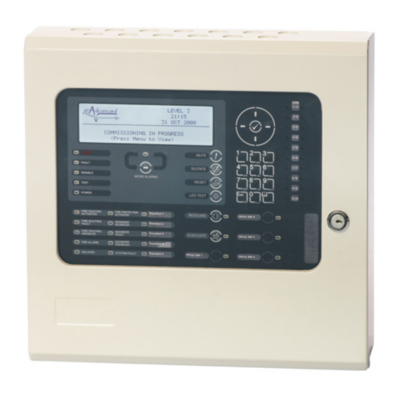
2 Installation Identification of Parts The following diagrams show the major parts of the panels. 2.1.1 5100 /S Enclosure comprises: Back Box Door Back box Base Card with 1x Loop AC Input Driver mounted onto a Chassis Plate Door with Display Card Display Cable mounted onto a fascia... - Page 12 2.1.2 5200 /M Enclosure comprises: Back Box Base Card with 2x Loop Door Back box Display Drivers mounted onto a AC Input Chassis Plate Door with Display Card mounted onto a fascia Display Cable plate. Key-Lock. WARNING: HIGH VOLTAGE INSIDE DO NOT REMOVE COVER Option for eight key- No Serviceable Parts Inside...
- Page 13 2.1.3 5400 /L, /D Enclosures comprises: Back Box Base Card with 1-4 Door Back box Display Loop Drivers mounted AC Input onto a Chassis Plate Door with Display Card mounted onto a fascia plate. Key-Lock. Display Cable Option for eight key- WARNING: HIGH VOLTAGE INSID DO NOT REMOVE COVER...
-
Page 14: 5000R
The rack module can be incorporated into 19” Commercially available rack enclosures (Sarel or Rittal) or in Advanced MXM-510-XXU Rack enclosures. Weight: 6Kg For more information on the rack system and optional modules, see document 680-195. -
Page 15: Installing The Enclosure
Installing the Enclosure The panel weight is heavy when the batteries are installed. Use the appropriate fixing hardware to secure the panel to the wall. Observe recommended lifting practices to guard against spinal injury. See table below for maximum weights. Enclosure Weight Maximum Battery... - Page 16 (/S) Enclosure Size and knockouts (top) Knockouts x2 (/M) Enclosure Size and knockouts (top) 183.5 183.5 (/M) Enclosure Size and Fixing Point Dimensions (/L Enclosure Size and knockouts (top) (/D Enclosure Size and knockouts (top) Knockouts /L x2, /D x3 183.5 183.5 (/L, /D) Enclosure Size and Fixing Point Dimensions...
-
Page 17: Remounting The Chassis
(/E Enclosure Size and knockouts (top) (/E) Enclosure Size and Fixing Point Dimensions MXM-510-16U Enclosure Size and Fixing Point Dimensions 2.2.4 Remounting the Chassis Carefully replace the chassis and fix into place using the two screws. Reconnect the chassis earth cable to the spade terminal in the rear of the enclosure, reconnect the display cable to the display card and then reconnect the AC supply lead to the Base Card. -
Page 18: Recommended Cable Routing Arrangement
2.2.5 Recommended Cable Routing Arrangement It is recommended that the typical routing arrangement AC INPUT shown in the diagram opposite be LOOPS AUX, PBUS & SW I/P RELAYS SOUNDERS employed. Segregate the low AC Input voltage wiring (Loop Circuit, Sounder Circuits and AUX Supply) from the AC Mains Wiring. -
Page 19: Loop Driver Installation
Loop Driver Installation The 5100, 5100V and 5100N panels are factory fitted with one loop driver. The 5200, 5200V and 5200N panels can be fitted with up to two loop drivers – factory fitted with at least one loop driver. The 5400, 5400V and 5400N panels can be fitted with up to four loop drivers –... -
Page 20: Removing A Loop Driver Card
2.3.2 Removing a Loop Driver Card To remove a loop driver, remove all power and follow the procedure above but: Take a firm hold of top of the loop driver card. Gradually and carefully pull the loop driver vertically away from the base card and guide it out of the slots in the card guides. Plug-In / Peripheral Bus Modules All panels provide provision for installation / use of local peripheral cards to provide additional functions. -
Page 21: 2-Way Relay Card (Plug-In)
2.4.2 2-Way Relay Card (Plug-In) The Mxp-507 Relay 2-Way Relay card is fitted to the base card using 2x plastic pillars. Refer to the diagram opposite. All signals and power required for operation of the card are provided WARNING: HIGH VOLTAGE INSIDE on the plug-in DO NOT REMOVE COVER No Serviceable Parts Inside... -
Page 22: Peripheral Module Chassis Mounting
2.4.4 Peripheral Module Chassis Mounting A Peripheral Module can be installed onto the chassis plate in the medium, large and deep enclosures. The peripheral card is fitted to the chassis using 4x M3 screws. All cards require connections to a 24V DC supply (AUX 24V) and to the PBUS communications. Refer to wiring section for further information. -
Page 23: Vds Interface Module Chassis Mounting
2.4.5 VdS Interface Module Chassis Mounting An Mxp-504 VdS Interface Module can be installed onto the chassis plate in the medium, large and deep enclosures. Outputs to Routing Equipment – Clauses 7.9 and 8.9. The Routing Interface Card provides monitored outputs for connection to Fire Routing Equipment (Item E) in accordance with EN54-2. -
Page 24: Wiring Installation
Wiring Installation All electrical wiring installation work should be carried out in accordance with the code of practice or applicable national standards appropriate to the country of installation. To maintain electrical integrity of the SELV wiring on the input, output, loop and communications lines all SELV wiring should be segregated from the LV mains wiring and be wired using cable with insulation suitable for the application. -
Page 25: Battery Installation
2.5.2 Battery Installation The panel requires two 12V Base Card Terminations batteries for standby operation. The battery leads are connected onto the base card via a two-part plug and socket, as shown in the diagram opposite. Refer to the Specifications for minimum and maximum battery WARNING: HIGH VOLTAGE INSIDE... -
Page 26: Medium Enclosure
2.5.2.2 Medium Enclosure The diagrams opposite show the recommended location and orientation for 7Ah – 12AH batteries within the panel. WARNING: HIGH VOLTAGE INSIDE DO NOT REMOVE COVER No Serviceable Parts Inside 2.5.2.3 Large Enclosure The diagrams opposite show the recommended location and orientation for 7Ah –... -
Page 27: Deep Enclosure
2.5.2.4 Deep Enclosure The diagrams opposite show the recommended location and orientation for 7Ah – 38AH/45AH batteries within the panel. WARNING: HIGH VOLTAGE INSID DO NOT REMOVE COVER No Serviceable Parts Inside www.advancedco.com... -
Page 28: Detector Loop Installation
2.5.3 Detector Loop Installation Maximum of 32 Sensors / Call Points in a Zone (between Isolators). The Detection Loop Circuit should be installed as a continuous Clause 6.2.5 Not more than 128 loop with isolator modules such that a short circuit condition devices per loop does not remove more than one zone or 32 input devices. -
Page 29: Sounder Circuits
2.5.4 Sounder Circuits The 5100 & 5200 are equipped with two supervised sounder circuits. These are denoted as Circuits A and B. The 5400 is equipped with four supervised sounder circuits. These are denoted as Circuits A, B, C and D. Each Sounder output is rated at a maximum of 1 Ampere. -
Page 30: Network Interface
2.5.5 Network Interface The network permits the connection of other panels, remote terminals and other devices to complete a distributed system. Either an Mxp-503 (STD) standard network interface card or an Mxp-509 (FT) fault tolerant network interface card must be installed in the panel. All network nodes must be installed with the same type of interface. -
Page 31: Relay Circuits
2.5.6 Relay Circuits Fault Output. Relay 1 is arranged for failsafe operation as standard. Section 8.8 The MxPro 5 Series are equipped with two relay RELAY 1 RELAY 2 outputs. These are normally programmed to activate on Fault and Fire Alarm conditions respectively. -
Page 32: Switch Inputs
2.5.9 Switch Inputs 2.5.9.1 Base Card PBUS SWITCH One Switch input is provided on the base card (I/P9) and up to eight key switch inputs (I/P1-8) are provided on the display card. These can be used for changing access level, performing “class change”... -
Page 33: Routing Interface
2.5.12 Routing Interface The Plug-In Routing Interface is used to output monitored signals to Fire Routing Equipment and Fault Routing Equipment or to Fire Protection Equipment. 2.5.12.1 Fire / Fault Routing Each function comprises of an output circuit and an input (confirmatory) circuit. MONITORED Each output is monitored for open circuit and short INPUT CIRCUIT... -
Page 34: Vds Interface
2.5.13 VdS Interface The Mxp-504 is a chassis mount interface is used to connect the panel to dedicated equipment required in Germany and other markets (not available in all markets). The interface provides input / output circuits for 1 2 3 4 5 6 7 8 9 10 11 12 13 14 15 16 17 18... -
Page 35: Fat / Fbf Direct Connection
2.5.13.1 FAT / FBF Direct Connection The interface is compatible with IFAM FAT3000 and FBF2003 products using IHD protocol. Both the FAT and FBF can be directly connected to the interface card. When the FAT and FBF are closely coupled or included in a common housing, connect the FBF via the RS232 connections to the FAT. -
Page 36: Fat / Fbf Redundant Connection
2.5.13.2 FAT / FBF Redundant Connection Where several FAT terminals need to be connected, or where a redundant connection is required from several control panels, connect the FAT units via a redundant ring. This requires the installation of an IFAM ADP-N3E Interface in one panel and (optionally) an IFAM ADP-N3S Interface in a second panel if required. -
Page 37: Üe Fire Routing
2.5.13.4 ÜE Fire Routing The interface is compatible with routing equipment with a range of coil impedances from 200Ω-5000Ω. If the ÜE output is not used, fit one of the supplied 4K7 resistors across terminals 12&13. 24VDC Power can be supplied to the routing Router equipment if required. -
Page 38: Programming
3 Programming Introduction These instructions cover the configuration and programming of the panels. Where you see the “PC Only” symbol, these features can either only be set-up using the PC Configuration Tool or there are additional options that are only available via the PC Configuration Tool. -
Page 39: Changing Text Descriptions
3.1.4 Changing Text Descriptions Various parameters can have a text description defined. These include loop devices, zones, etc. The zone and device text descriptions will be shown on the display in the Fire Alarm, Fault and Warning Conditions, etc. to provide a quick and clear indication of the source of the problem. -
Page 40: Level 3 Menu Functions
If the number is entered incorrectly, press the ‘Esc’ button to restore the previous number. Level 3 Menu Functions The following table gives a list of the Level 3 Menu Functions, the sub-functions available within each main function and a brief description for each function. The menu options are available on three pages – select “Next Menu”... -
Page 41: Recommended Programming Procedure
Recommended Programming Procedure The main programming steps required will necessarily be different for each installation. However, the following is the minimum recommended. Step 1 – SET-UP, Define General Set-up Information (Phone Numbers, etc.). Step 2 – PASSWORDS, Define Level 2 and Level 3 Passwords as required. ... -
Page 42: Type
This parameter cannot be changed. 3.3.2.2 Type This parameter shows the type of device learnt by the panel. For example, this can show Call Point, Multi- Sensor, ION Smoke, Heat, etc. This parameter cannot be changed. 3.3.2.3 Value This parameter shows the analogue value returned by the device. The number displayed will vary according to the type of device fitted. -
Page 43: Sensitivity
Action Description Fire Signal A Fire Alarm Condition will be generated whenever the input is active. Pre-Alarm A Pre-Alarm Condition will be generated whenever the input is active. Supervisory A Supervisory Condition will be generated whenever the input is active An “Alarm 1”... - Page 44 Mode This option is shown on the display for specific device types only. Refer to the appropriate protocol application note for further information. Delay The value in this field defines the delay from detecting an alarm to entering the alarm condition. The delay time can be changed in 1-second increments.
-
Page 45: O/P Group
3.3.2.8 O/P Group The Output Group assigned to the Sounder or Relay Devices determines the manner in which the outputs will operate when a fire alarm or other programmed condition occurs. For example: [Loop 1 Devices] <More> Address O/P Group 020.0 021.0 022.0... -
Page 46: Loops - Auto Learn
3.3.3 Loops – Auto Learn 3.3.3.1 Normal Procedure / Initial learn The panel can automatically learn the presence or absence of devices at all addresses connected to the loop. When the Auto Learn option is selected, the panel starts searching each address on the loop to locate and find all of the devices connected. -
Page 47: Procedure If The Panel Finds Devices Changed
ACCEPT NEW DEVICE REJECT NEW DEVICE ACCEPT ALL NEW DEVICES REJECT ALL NEW DEVICES Address 002 NEW DEVICE If the new device is accepted (or all new devices are accepted), the panel will configure the memory to register these devices. All data will be configured to initial settings for sensitivity threshold changes, text assignments, zone assignment, action, etc. -
Page 48: Loop - Meter
Item Description Last Activation The date and time that the device was last activated (e.g. smoke level detected is at pre-alarm or alarm levels or the last time that an output was turned on). Last Test The date and time that the device was last tested (e.g. smoke level detected is at pre-alarm or alarm levels or the last time that an output was turned on). -
Page 49: Zones
3.3.8 Zones The Commission Zones option lists all the zones in use by this panel and allows the zone text description to be changed. [Commission Zones] Zone Location 0001 BASEMENT WEST 0002 RECEPTION 0015 EAST WING 0018 TOWER BLOCK To change the location text assigned to the Zone, press the ✔ button when the Zone Location Text is highlighted. -
Page 50: View Options
3.3.12 View Options The View Menu Options are identical to those available during Level-2 operation – refer to User Manual for further information. 3.3.13 Passwords The panel provides up to 10 User Level-2 passwords and 2 Level-3 passwords. All of the passwords can be changed. -
Page 51: En54-13
3.3.16 EN54-13 The EN54-13 menu defines whether EN54-13 transmission path monitoring is in use and defines the actual load current (shown in milliamps) to be used in the calculation for each of the base card loop and sounder circuits. If enabled, the panel monitors the circuits to ensure that at the specified load current, the circuit can deliver the load current whilst still maintaining circuit device voltage compatibility levels via the transmission path resistance. -
Page 52: Service Number
3.3.17.3 Service Number The Service Number is the telephone number that is shown on the status display whenever a fault condition is accepted. To change the number, press the ✔ button when the option is highlighted. The number is entered using the text entry facility;... -
Page 53: Earth Fault Notification
The device LED indicators will not blink if NONE is chosen or will blink if ALL is chosen. Note that only certain devices, such as Apollo Discovery, support this feature. If a device, such as a Discovery device, is changed it may be necessary to select and reconfirm the blinking command so that the new device will blink its LED. -
Page 54: Display
3.3.18 Display Depending on the physical mounted height of the panel, the contrast of the LCD may need adjusting to obtain optimum viewing. The display option permits the contrast adjustment of the LCD. [DISPLAY OPTIONS] ADJUST CONTRAST Press the ✔ button. The following display is shown: Use the ... -
Page 55: Ac Fail Delay
3.3.19.1 AC Fail Delay The panel can be configured to delay the reporting of a loss of AC Mains supply (Address 14.0). The front panel Green Power LED will still immediately flash on the loss of the AC Supply, but the fault condition is only reported after the delay time (default 10s) has elapsed. -
Page 56: Output Groups
3.3.20 Output Groups The “Cause and Effect” programming is a schedule of actions that will turn on one or more outputs dependant on a set of input events. The Outputs Option provides the means to create simple or complex “cause and effect” programming within the panel. -
Page 57: Cause
3.3.20.2 Cause Each Output Group can be programmed to respond in a unique way to events from each individual zone. An input event may be a fire alarm condition or it may be a fault, disablement or other condition. A combination of criteria may also be applied to each zone. -
Page 58: Style
3.3.20.3 Style The way in which an output turns on in response to a particular input event can be programmed. For example, an output may turn on immediately, it may turn on after a delay or it may pulse for a set time and then turn on. This method of operation is called a Style. -
Page 59: Overriding Delays At Level 1
Delays to Outputs. It must be possible to override the operation of any delays at Level 1. Refer to Section 3.3.21.1 for information on overriding delays. Section 7.11 For compliance, the maximum total delay permitted is 10 minutes. 3.3.21.1 Overriding Delays at Level 1 A facility to override any programmed delays and immediately activate the sounder circuits should be provided at Level 1. -
Page 60: Service And Maintenance
4 Service and Maintenance Maintenance Schedule This equipment should be maintained in accordance with the regulations and codes appropriate to the country and location of installation. The following is recommended if no other regulations apply. 4.1.1 Daily Actions The site operator / user should perform the following checks and actions: a) The panel indicates normal operation. -
Page 61: Replacement Of Components
Replacement of Components In general, all of the components parts used in the construction of the panel have been selected for long life and reliability. However, certain components may require to be changed on a regular service basis. The details of these are as follows: 4.2.1 Batteries For battery installation, see section... -
Page 62: Liquid Crystal Display
4.2.2 Liquid Crystal Display Expected Life: > 10 years Replacement Schedule: When the display becomes difficult to read. The display contrast will gradually fade with time. Manufacturer / Part Number: Replace the complete display / keyboard assembly. Spare part number MXS 504. -
Page 63: Appendices
5 Appendices Appendix 1 – Forgotten Level 3 Password Should the Level-3 password be forgotten, contact Customer Support to obtain a temporary permit number to regain access to the panel programming functions. Customer Support will require a decryption key displayed by the panel. To obtain this number, attempt to gain access to the Level-3 Programming Functions entering “1”... -
Page 64: Appendix 2 - Recommended Fire Rated Cables
Appendix 2 – Recommended Fire Rated Cables The following table provides a list of suitable fire rated cables with standard (30 minute) and enhanced (120 minute) classification. Refer to Document No. 680-088 for an up to date list. Core Sizes (mm) 5839-1 Rated Manufacturer Cable Type... -
Page 65: Sounder Circuit Lengths
5.2.2 Sounder Circuit Lengths The voltage drop on each alarm circuit should be calculated to ensure that the minimum voltage at the end of the circuit exceeds the minimum required by each sounding device at the minimum alarm circuit output voltage. The voltage at the end of the circuit is given by: –... -
Page 66: Appendix 3 - Battery Standby Calculation Chart
Appendix 3 – Battery Standby Calculation Chart Use the following charts and associated notes to calculate the size of the batteries required to ensure operation of the installation in the event of AC Mains power failure. This chart is applicable to all panels except: 5100N, 5200N and 5400N Quiescent Load Fire Alarm Load... -
Page 67: Appendix 4 - Cause And Effect Programming Example
Appendix 4 – Cause and Effect Programming Example 5.4.1 Introduction By default, all sounders and output devices will turn on immediately as soon as a fire is detected anywhere in the system. For example: Cause Effect Any Fire, Anywhere. ALL Output Devices will Turn ON Quite often an installation will require a more complex “Cause and Effect”... -
Page 68: Output Group Programming
5.4.4 Output Group Programming To achieve the above cause and effect requirements, the three different Output Groups would be programmed and indicated on the panel as in the following display examples: Output Group 6 – Sounders on Floor 6: [Output Group 3.9% Mem used] [STYLE 02 ZONE CAUSE... -
Page 69: Appendix 5 - Other Useful Documents
The following reference and application documents may be useful in the design, configuration and installation of the system. The latest versions of these and new / additional application notes are available from the Advanced web site (www.advancedco.com) or in hard copy format from Sales. -
Page 70: Appendix 6 -Network Design Principles
Appendix 6 –Network Design Principles This section gives recommendations on the design of the installation to cover specific EN54-2 requirements and typical national codes of practice. [EN54-2: 1997, Clause 13.7] Not more than 512 fire detectors and / or manual call points and their associated mandatory functions shall be affected as a result of a system fault in the C.I.E. -
Page 71: Appendix 7 - M
Appendix 7 – Mx Series Product Capabilities / Max Limits This section gives details on the maximum capabilities for each of the products in the range. Some of the items can only be utilised via the PC CONFIG tool and these are annotated accordingly. 5100 5200 5400... - Page 72 This page is intentionally left blank. www.advancedco.com...
- Page 73 USER NOTES www.advancedco.com...
- Page 74 Doc Number: 680-165 Revision: First Issued: 2010-10-19 Advanced Electronics Ltd Moorland Way, Cramlington, Northumberland, NE23 1WE UK Tel: +44 (0)1670 707 111 Fax: +44 (0)1670 707 222 Email: sales@advancedco.com Web: www.advancedco.com www.advancedco.com...
Need help?
Do you have a question about the MxPro 5 Mx-5100 and is the answer not in the manual?
Questions and answers