
Related Manuals for ASROCK N4200-NUC IPC


Summary of Contents for ASROCK N4200-NUC IPC
- Page 1 N4200-NUC IPC N3350-NUC IPC User Manual Version 1.0 Published June 2018 Copyright©2018 ASRock INC. All rights reserved.
- Page 2 (including damages for loss of profits, loss of business, loss of data, interruption of business and the like), even if ASRock has been advised of the possibility of such damages arising from any defect or error in the documentation or product.
- Page 3 The terms HDMI™ and HDMI High-Definition Multimedia Interface, and the HDMI logo are trademarks or registered trademarks of HDMI Licensing LLC in the United States and other countries. CAUTION: RISK OF EXPLOSION IF BATTERY IS REPLACED BY AN INCORRECT TYPE. DISPOSE OF USED BATTERIES ACCORDING TO THE INSTRUCTIONS.
-
Page 4: Table Of Contents
Contents 1 Introduction ............5 1.1 Package Contents ............5 1.2 Specifications ..............6 1.3 Motherboard Layout ............8 1.4 I/O Panel ................ 9 2 Installation ............10 2.1 Screw Holes ..............10 2.2 Pre-installation Precautions ........... 10 2.3 Installation of Memory Modules (SO-DIMM) ....11 2.4 Expansion Slots ............ -
Page 5: Introduction
In case any modifications of this manual occur, the updated version will be available on ASRock website without further notice. You may find the latest VGA cards and CPU support lists on ASRock website as well. ASRock website http://www.asrock.com If you require technical support related to this motherboard, please visit our website for specific information about the model you are using. -
Page 6: Specifications
1.2 Specifications Form Dimensions 4.09" x 4.02" (104 x 102mm) Factor ® Processor Intel Apollo Lake N4200/N3350 SoC ® Chipset Intel System PCIe Mini-PCIe Expansion mSATA Slot 1 x M.2 2230, Key E (PCIe x1 +USB2.0), 1 x M.2 2242/2260, Key M with SATA3 for SSD Technology Dual Channel DDR3L 1867 Memory Max. - Page 7 2 x USB2.0 LVDS/ inverter Serial Internal SATA 1 x SATA3 (6.0 Gb/s) Connector Parallel GPIO SATA PWR Output Speaker Header SPI TPM on-board design Watchdog Output From Super I/O to drag RESETCON# Timer Interval 256 segments, 0,1,2…255sec Input PWR 12V DC-In (DC Jack) Power ATX Supported...
-
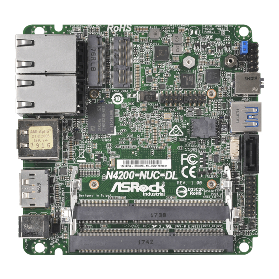
Page 8: Motherboard Layout
1.3 Motherboard Layout CLRMOS1 PANEL1 AUDIO1 COM1 USB2_4_5 USB3_2 BIOS Chip SATA_PWR1 SATA3_1 N4200-NUC-DL Industrial DDR3_A1 (Support DDR3L Only) DC_IN1 DDR3_B1 (Support DDR3L Only) 1 : M.2 Socket (Key-M) (M2M_1) 2 : M.2 Socket (Key-E) (M2E_1) 3 : Clear CMOS Header (CLRMOS1) 4 : COM Port Header (COM1) 5 : USB2.0 Header (USB2_4_5) 6 : ATX/AT Mode Select (PWR_JP1) -
Page 9: I/O Panel
1.4 I/O Panel LAN RJ-45 Port (LAN1)* HDMI Port (HDMI1) USB 3.0 Port (USB3_1) DisplayPort (DISPLAY1) LAN RJ-45 Port (LAN2)* DC-In Jack (DC_IN1) USB 3.0 Port (USB3_3) USB 3.0 Port (USB3_2) DisplayPort (DP2) Audio Jack (AUDIO1) * There are two LED next to the LAN port. Please refer to the table below for the LAN port LED indications. -
Page 10: Installation
Chapter 2: Installation Before you install the motherboard, study the configuration of your chassis to ensure that the motherboard fits into it. Make sure to unplug the power cord before installing or removing the motherboard. Failure to do so may cause physical injuries to you and damages to motherboard components. -
Page 11: Installation Of Memory Modules (So-Dimm)
2.3 Installation of Memory Modules (SO-DIMM) N4200-NUC IPC / N3350-NUC IPC motherboard provides two 204-pin DDR3 (Double Data Rate 3) SO-DIMM slots, which support Dual Channel DDR3L (low voltage). 1. It is not allowed to install a DDR or DDR2 memory module into a DDR3 slot;... -
Page 12: Expansion Slots
2.4 Expansion Slots (M.2 Sockets) There are 2 M.2 sockets on this motherboard. M.2 Sockets: 1 x M.2 2230, Key E (PCIe x1 +USB2.0) 1 x M.2 2242/2260, Key M (SATA3) M.2 Socket (Key-M) (M2M_1) M.2 Socket (Key-E) (M2E_1) Signal Name Signal Name Signal Name Signal Name... -
Page 13: Jumpers Setup
2.5 Jumpers Setup The illustration shows how jumpers are setup. When the jumper cap is placed on pins, the jumper is “Short”. If no jumper cap is placed on pins, the jumper is “Open”. The illustration shows a 3-pin jumper whose pin1 and pin2 are “Short”... -
Page 14: Onboard Headers And Connectors
2.6 Onboard Headers and Connectors Onboard headers and connectors are NOT jumpers. Do NOT place jumper caps over these headers and connectors. Placing jumper caps over the headers and connectors will cause permanent damage of the motherboard! SATA Power Output Connector Please connect a SATA power cable to this connector. - Page 15 The front panel design may differ by chassis. A front panel module mainly consists of power switch, reset switch, power LED, hard drive activity LED, speaker and etc. When connecting your chassis front panel module to this header, make sure the wire assignments and the pin assign-ments are matched correctly.
-
Page 16: Uefi Setup Utility
Chapter 3: UEFI SETUP UTILITY 3.1 Introduction This section explains how to use the UEFI SETUP UTILITY to configure your system. The UEFI chip on the motherboard stores the UEFI SETUP UTILITY. You may run the UEFI SETUP UTILITY when you start up the computer. Please press <F2>... -
Page 17: Navigation Keys
3.1.2 Navigation Keys Please check the following table for the function description of each navigation key. Navigation Key(s) Function Description Moves cursor left or right to select Screens Moves cursor up or down to select items + / - To change option for the selected items <Enter>... -
Page 18: Advanced Screen
3.3 Advanced Screen In this section, you may set the configurations for the following items: CPU Configu- ration, Chipset Configuration, Storage Configuration, Super IO Configuration, ACPI Configuration and Trusted Computing. Setting wrong values in this section may cause the system to malfunction. Instant Flash Instant Flash is a UEFI flash utility embedded in Flash ROM. -
Page 19: Cpu Configuration
3.3.1 CPU Configuration Intel SpeedStep Technology Intel SpeedStep technology is Intel’s new power saving technology. Pro- cessors can switch between multiple frequencies and voltage points to en- able power saving. The default value is [Enabled]. Configuration options: ® [Enabled] and [Disabled]. If you install Windows OS and want to enable this function, please set this item to [Enabled]. - Page 20 Power Gear Toggle between three operational modes (Eco, Normal and Sport) to maxi- mize performance or conserve energy. Eco Mode: Reduces your computer’s performance and saves energy. Normal Mode: Balance performance with power consumption. Sport Mode: Use more power to achieve the highest performance.
-
Page 21: Chipset Configuration
3.3.2 Chipset Configuration DRAM Frequency If [Auto] is selected, the motherboard will detect the memory module(s) inserted and assign the appropriate frequency automatically. Share Memory Configure the size of memory that is allocated to the integrated graphics processor when the system boots up. Onboard HD Audio Select [Auto], [Enabled] or [Disabled] for the onboard HD Audio feature. -
Page 22: Storage Configuration
3.3.3 Storage Configuration SATA Controller(s) Use this item to enable or disable the SATA Controller feature. SATA Mode Selection Use this to select SATA mode. The default value is [AHCI Mode]. AHCI (Advanced Host Controller Interface) supports NCQ and other new features that will improve SATA disk perfor- mance but IDE mode does not have these advantages. -
Page 23: Super Io Configuration
3.3.4 Super IO Configuration COM1 Configuration Use this to set parameters of COM1. Select COM1 port type: [RS232], [RS422] or [RS485]. WDT Timeout Reset This allows users to enable/disable the Watch Dog Timer timeout to reset system. The default value is [Disabled]. -
Page 24: Acpi Configuration
3.3.5 ACPI Configuration Suspend to RAM Use this item to select whether to auto-detect or disable the Suspend-to- RAM feature. Select [Auto] will enable this feature if the OS supports it. ACPI HPET Table Use this item to enable or disable ACPI HPET Table. The default value is [Enabled]. -
Page 25: Trusted Computing
3.3.6 Trusted Computing Security Device Support Enable or disable BIOS support for security device. -
Page 26: Hardware Health Event Monitoring Screen
3.4 Hardware Health Event Monitoring Screen In this section, it allows you to monitor the status of the hardware on your system, including the parameters of the CPU temperature, motherboard temperature, CPU fan speed, chassis fan speed, and the critical voltage. CPU Fan 1 Setting Select a fan mode for CPU Fan 1, or choose Customize to set 5 CPU tem- peratures and assign a respective fan speed for each temperature. -
Page 27: Security Screen
3.5 Security Screen In this section, you may set, change or clear the supervisor/user password for the system. Supervisor Password Set or change the password for the administrator account. Only the ad- ministrator has authority to change the settings in the UEFI Setup Utility. Leave it blank and press enter to remove the password. -
Page 28: Boot Screen
3.6 Boot Screen In this section, it will display the available devices on your system for you to config- ure the boot settings and the boot priority. Boot From Onboard LAN Use this item to enable or disable the Boot From Onboard LAN feature. Setup Prompt Timeout This shows the number of seconds to wait for setup activation key. - Page 29 CSM (Compatibility Support Module) Enable to launch the Compatibility Support Module. Please do not disable unless you’re running a WHCK test. If you are using Windows 8.1 64-bit and all of your devices support UEFI, you may also disable CSM for faster boot speed.
-
Page 30: Exit Screen
3.7 Exit Screen Save Changes and Exit When you select this option, it will pop-out the following message, “Save configuration changes and exit setup?” Select [OK] to save the changes and exit the UEFI SETUP UTILITY. Discard Changes and Exit When you select this option, it will pop-out the following message, “Discard changes and exit setup?”... -
Page 31: Software Support
Click on a specific item then follow the installation wizard to install it. 4.2.4 Contact Information If you need to contact ASRock or want to know more about ASRock, you’re welcome to visit ASRock’s website at http://www.asrock.com; or you may con-...
Need help?
Do you have a question about the N4200-NUC IPC and is the answer not in the manual?
Questions and answers