Table of Contents
Advertisement
Available languages
Available languages
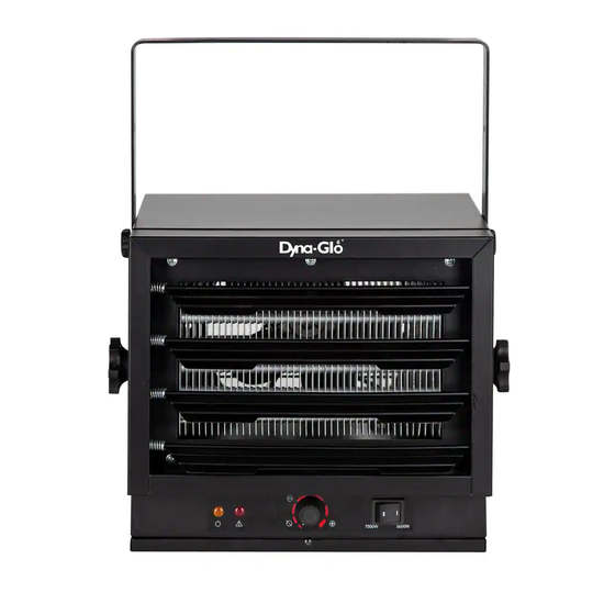
EG7500DGC
Electric Garage Heater
7 ,500W / 240V / 25,590 BTU
INSTALLATION & MAINTENANCE INSTRUCTIONS
Before the first use of this heater, please read this USER'S MANUAL
very carefully. This USER'S MANUAL has been designed to instruct
you as to the proper manner in which to assemble, maintain, store,
and most importantly, how to operate the heater in a safe and efficient
manner. Please keep this manual for future reference.
CONSUMER: Retain this manual for future reference.
Questions, problems, missing parts? Before returning to your retailer, call our customer
service department at 877-447-4768 8:00 a.m. - 4:30 pm CST, Monday - Friday.
or email us at customerservice@ghpgroupinc.com
190625
Advertisement
Chapters
Table of Contents

Related Manuals for Dyna-Glo EG7500DGC


Summary of Contents for Dyna-Glo EG7500DGC
- Page 1 EG7500DGC Electric Garage Heater 7 ,500W / 240V / 25,590 BTU INSTALLATION & MAINTENANCE INSTRUCTIONS Before the first use of this heater, please read this USER’S MANUAL very carefully. This USER’S MANUAL has been designed to instruct you as to the proper manner in which to assemble, maintain, store, and most importantly, how to operate the heater in a safe and efficient manner.
- Page 2 IMPORTANT INSTRUCTIONS When using electrical appliances, basic precautions should always be followed to reduce the risk of fire, electric shock, and injury to persons, including the following: 1. Read all instructions before installing or using this heater. 2. This heater is hot when in use. To avoid burns, do not let bare skin touch hot surfaces.
-
Page 3: Table Of Contents
TABLE OF CONTENTS ITEM PAGE # SPECIFICATIONS ................SAFETY INFORMATION ..............LOCATING HEATER ............... PRE-INSTALLATION ............... INSTALLATION ................OPERATING INSTRUCTIONS ............MAINTENANCE ................REPLACEMENT PARTS ..............TROUBLESHOOTING ..............SPECIFICATIONS Rating AMPS BTU/hour 7500W II 240-1-60 31.25 25590 5000W I 240-1-60 20.9 17065 SAFETY INFORMATION... -
Page 4: Safety Information
SAFETY INFORMATION 6. All electrical power must be disconnected at the main service box, which must be locked before connecting, inspecting, cleaning or servicing the heater. This is an important precaution to prevent serious electric shock. 7. This is heater is not suitable for use in hazardous locations containing explosive l iquids or vapours. This heater has hot or arcing or sparking pads inside. Do not use it in areas where gasoline, paint or flammable liquids are used or stored. 8. This heater is not suitable for use in corrosive atmospheres such as marine greenhouses or chemical storage areas. 9. This heater must be mounted at least 8 feet off the floor. For specific clearances, please see next page. WARNING IMPROPER INSTALLATION OR FAILURE TO FOLLOW THE PROCEDURES OUTLINED IN THIS INSTRUCTION MANUAL CAN RESULT IN SERIOUS ELECTRICAL SHOCK. LOCATING HEATER Install heater away from traffic areas, maintaining clearances stated in figure 2 (below). The air flow direction should not be restricted (ie. by columns or machinery). The air flow should wipe exposed walls rather than blowing directly... -
Page 5: Pre-Installation
LOCATING HEATER Figure 3 PRE-INSTALLATION Part Description Quantity Garage Heater Mounting Bracket Screw Washer... -
Page 6: Installation
INSTALLATION MOUNTING THE BRACKET Refer to Figures 4a and 4b. 1. Locate a wood stud in the wood ceiling joist. If you cannot locate a wood stud, you have to install a wood piece on the ceiling as this heater must be securely fastened. 2. Remove the mounting bracket from the heating unit by loosening bracket screws with a wrench and slipping the handle off over the screw heads. 3. Place a washer on screws before inserting through the holes in the mounting bracket and screw them securely into a ceiling joist. NOTE: If you want to swivel the heater either to the right or left adding a washer to both sides of the bracket is recommended. A longer lag bolt may be required to properly secure the unit. See Figure 4a. Wood Ceiling Wood Ceiling Figure 4a. Single-Screw Mounting Figure 4b. Double-Screw Mounting HANGING THE HEATER 1. Attach the heating unit to the mounting bracket. 2. Lift the heater up and into the mounting Figure 5 bracket. 3. Align the bracket screws with the keyhole slots in the mounting bracket. - Page 7 INSTALLATION NOTE: For the heater to be tilted vertically, it must be mounted in bottom keyhole slots of mounting brackets to maintain adequate clearance and prevent possible overheating. Figure 6 3. A djust louvers to the desired position (see Figure 6). NOTE: The louvers are designed so they cannot be completely closed. Do not attempt to bypass this feature; damage to the unit can result. WARNING TO PREVENT POSSIBLE ELECTRIC SHOCK, DISCONNECT POWER TO THE HEATER AT THE MAIN SERVICE BOX BEFORE ATTEMPTING TO ADJUST THE HEAT OUTPUT OF THIS UNIT. MULTIPLE VERTICAL ANGLES CEILING 90 degrees 45 degrees 90 degrees...
- Page 8 INSTALLATION CONNECTING THE POWER Switch 2500W 240AC or 208AC 60HZ 2500W 2500W External thermostat Selected Heater's switch thermostat Heater’s External thermostat thermostat Selection Switch (Heater’s thermostat, External thermostat) If you will use an external temperature control (external thermostat) to control the heater to be operated or not, please follow below attention points: 1. Make sure that the heater's temperature control knob (thermostat knob) is turned fully clockwise.
- Page 9 INSTALLATION CONNECTING THE POWER 3. The external temperature control (external thermostat) should be in accordance with the requirement of UL or CSA standard. 4. The lead wire of external temperature control (external thermostat) can not be less than 14AWG. TO PROTECT THE HEATING ELEMENT When starting the heater, turning the temperature control clockwise slowly to terminal, the unit starts the fan first then starts the heating element. When shutting off the heater, turning the temperature control counter-clockwise to off, the heating element first will turn off then the fan will run a short cooling cycle and then turn off. WARNING THIS APPLIANCE MUST BE GROUNDED! THE APPLIANCE MUST CONNECT TO A CURRENT PROTECTION CIRCUIT OR DEVICE AT 50AMP OR LESS BEFORE BEING CONNECTED TO POWER SUPPLY! 1. Remove the screw from the front of the unit to connect the power to the heater.
-
Page 10: Operating Instructions
INSTALLATION CONNECTING THE POWER Conduit Conduit Connector BLACK Flexible Conduit Flexible Conduit Connector Flexible NM Cable Flexible NM Cable Connector WHITE GREEN (or bare copper) Connectors, cable, and hardware used to Figure 7 Figura 7 wire the heater OPERATING INSTRUCTIONS WARNING THE HEATER MUST BE PROPERLY INSTALLED BEFORE IT IS USED. Control Panel 7500W 5000W Power Indicator Caution Indicator Thermostat Switch (5000W / 7500W) - Page 11 OPERATING INSTRUCTIONS Check that the garage heaters outlet grill is not covered or obstructed in anyway, and make sure the power to the unit is switched on. SETTING THE THERMOSTAT 1. Rotate thermostat knob clockwise to desired position, POWER INDICATOR will turn yellow. 2. After room reaches desired comfort level the heater will turn off. Heater will cycle on and off to maintain room temperature. SELECTION SWITCH Using the SELECTION SWITCH, you can control the heating output: I for 5000W, II for 7500W. THERMAL CUT-OUT The heater will automatically shut off when parts of it overheat. The heater will turn ON again when the abnormal temperature returns to normal levels. Should the unit overheat and cause the thermal cut-out to cycle, the cause of the overheating should be determined and corrective action taken before further operation. NOTE: When the thermal cut-out is activated, the caution indicator will turn red. In this case, immediately turn the heater OFF and inspect for any objects on or adjacent to the heater that may cause high temperatures. DO NOT OPERATE THE HEATER WITH THE CAUTION INDICATOIR GLOWING RED. ADJUSTING AIR FLOW DIRECTION 1. To turn the unit when it has been installed with a single lag bolt (as shown in figure 4a), simply turn the entire heater as needed. The unit cannot be turned horizontally if it has been installed with 2 lag bolts.
-
Page 12: Maintenance
MAINTENANCE 1. Before cleaning, make sure the power has been turned off at the circuit breaker panel and that the heating element of the heater is cool. 2. To maintain the external appearance of the heater, the unit occasionally needs to be wiped with a dry duster. During the summer months, or at other times when the appliance is not in use and is completely cold, it should be the wiped over with a damp cloth. 3. Do not use abrasive clearing powders or furniture polish. Do not use chemical or abrasive products, metallic scourers and so on, which may deteriorate the sur- face, to clean the appliance. 4. During the summer months, or at other times when the appliance is not in use, disconnect the power supply, and cover the whole appliance with a dustcloth. Moreover, keep the appliance in a dry and cool place. 5. All other servicing should be performed by qualified service personnel. Do not try to repair the heater yourself. REPLACEMENT PARTS Part Description Part# Part Description Part# Back mesh EG5000001AC Heater EG7500001AC Hanging plate EG5000002AC Selection Switch EG5000011AC Fan Blade EG5000003AC Thermostat EG5000012AC Air guide plate EG5000004AC Knob EG5000013AC Large handle seat EG5000005AC Terminal block... -
Page 13: Troubleshooting
TROUBLESHOOTING PROBLEM ROOT CAUSE CORRECTIVE ACTION Inspect the garage heater and check that the air inlets and outlets are not blocked as this may cause overheat- The overheat protection has ing. Switch off the circuit breaker to activated. Unit is not the garage heater for 30 minutes and heating. - Page 14 PRODUCT NOTES...
- Page 15 Warranty LIMITED WARRANTY: This limited warranty is extended to the original retail purchaser of this Forced Air/Convection/Radiant Heater and warrants against any defect in materials and workmanship for a period of one (1) year from the date of retail sale.GHP Group, Inc., at it’s option, will either provide replacement parts or replace or repair the unit, when properly returned to the retailer where purchased or one of our service centers as directed by GHP Group,Inc., within one (1) year of retail purchase.
- Page 16 WARRANTY REGISTRATION IMPORTANT: We urge you to fill out your warranty registration card within fourteen (14) days of date of purchase. You can also register your warranty on the internet at www.ghpgroupinc.com. Complete the entire serial number. Retain this portion of the card for your records.
- Page 17 EG7500DGC Calefactor de garaje eléctrico 7 ,500W / 240V / 25,590 BTU INSTRUCCIONES DE INSTALACIÓN Y MANTENIMIENTO Antes de utilizar por primera vez este calentador, lea este MANUAL DEL USUARIO atentamente. Este MANUAL DEL USUARIO ha sido diseñado para instruirle la forma adecuada de ensamblar el calentador, brindarle mantenimiento, guardarlo y lo más importante: cómo hacerlo funcionar de...
- Page 18 INSTRUCCIONES IMPORTANTES Al usar electrodomésticos, siempre se deben respetar las precauciones básicas para reducir el riesgo de incendio, choques eléctricos y lesiones personales, incluidas las siguientes: 1. Lea todas las instrucciones antes de instalar o usar este calefactor. 2. Este calefactor se calienta cuando está en uso. Para evitar quemaduras, no toque las superficies calientes con la piel descubierta.
- Page 19 CONTENIDO ARTÍCULO PÁGINA ESPECIFICACIONES ..............INFORMACIÓN GENERAL SOBRE SEGURIDAD ......UBICACIÓN DEL CALEFACTOR ............ PRE-INSTALACIÓN ................ INSTALACIÓN ................. INSTRUCCIONES DE USO ............MANTENIMIENTO Y LIMPIEZA ............. PIEZAS DE REPUESTO ..............SOLUCIÓN DE PROBLEMAS ............ESPECIFICACIONES Índice Amperios BTU/hora 7500W II 240-1-60 31.25 25590 5000W I 240-1-60...
-
Page 20: Ubicación Del Calefactor
INFORMACIÓN SOBRE SEGURIDAD 6. Se debe desconectar la alimentación eléctrica y bloquear la caja de servicio eléctrico antes de inspeccionar el calefactor, limpiarlo o realizarle mantenimiento. Esta es una precaución para evitar choques eléctricos graves. 7. Este calefactor no es apropiado para utilizarlo en ubicaciones peligrosas tal como las define la Asociación Nacional de Protección contra Incendios (NFPA, por su sigla en inglés) de Estados Unidos. El calefactor contiene piezas internas que se calientan, forman arcos eléctricos o generan chispas. No lo use en áreas donde se utilice o se guarde gasolina, pintura o líquidos inflamables. 8. Este calefactor no es apropiado para utilizarlo en atmósferas corrosivas, como zonas marinas, invernaderos o áreas de almacenamiento de productos químicos. 9. Este calefactor debe estar ubicado a 8 pies del piso, como mínimo. ADVERTENCIA INSTALAR INCORRECTAMENTE O NO RESPETAR LOS PROCEDIMIENTOS DESCRITOS EN ESTE MANUAL DE INSTRUCCIONES PUEDE DAR LUGAR A CHOQUES ELÉCTRICOS GRAVES. UBICACIÓN DEL CALEFACTOR Instale el calefactor fuera de las zonas de tránsito y mantenga los espacios libres indicados en la figura 2. La dirección del flujo de aire no debe estar restringida por columnas o máquinas. El flujo de aire solo debe rozar las paredes y no dirigirse directamente a ellas. Cuando se utiliza más de un calefactor en un área, los calefactores se deben disponer de modo que la descarga de aire de cada uno... -
Page 21: Pre-Instalación
UBICACIÓN DEL CALEFACTOR Figura 3 PRE-INSTALACIÓN Parte Descripción Cantidad Calentador de garaje Soporte de montaje Tornillo Arandela... -
Page 22: Instalación
INSTALACIÓN MONTAR EL SOPORTE Consulte las figuras 4a y 4b. 1. Localice un montante de madera en la viga del techo de madera. Si no puede localizarlo, debe instalar una pieza de madera en el techo porque el calefactor se debe sujetar de forma segura. 2. Retire el soporte de montaje de la unidad calefactora; para esto, afloje los tornillos del soporte con una llave y deslice la manija por afuera y por encima de las cabezas de los tornillos. 3. Coloque una arandela en los tornillos antes de insertarlos a través de los orificios del soporte de montaje y atorníllelos firmemente en la viga del techo. NOTA: Si desea que el calefactor gire hacia la derecha o hacia la izquierda, se recomienda agregar una arandela a ambos lados del soporte. Es posible que se necesite un tirafondo más largo para sujetar la unidad correctamente. Consulte la figura 4a. Techo de madera Techo de madera Figura 4a. Montaje de un solo tornillo Figura 4b. Montaje de dos tornillo COLGAR EL CALEFACTOR Figura 5 1. Fije la unidad calefactora al soporte de montaje. - Page 23 INSTALACIÓN NOTA: Las rejillas están diseñadas para que no se puedan cerrar por completo. No intente hacerlo porque puede dañar la unidad. Figura 6 3. A juste las rejillas a la posición deseada (consulte la figura 6). NOTA: Las rejillas están diseñadas para que no se puedan cerrar por completo. No intente hacerlo porque puede dañar la unidad. ADVERTENCIA PARA EVITAR POSIBLES CHOQUES ELÉCTRICOS, DESCONECTE LA ALIMENTACIÓN AL CALEFACTOR EN LA CAJA DE SERVICIO ELÉCTRICO ANTES DE INTENTAR AJUSTAR LA SALIDA DE CALOR DE LA UNIDAD. MÚLTIPLES ÁNGULOS VERTICALES TECHO 90 grados grados grados 45 grados...
- Page 24 INSTALACIÓN CONEXIÓN DE LA ALIMENTACIÓN Interruptor 2500W 240AC or 208AC 60HZ 2500W 2500W Termostato externo Interruptor de Termostato selección de calefactor Termostato del Termostato calefactor externo Interruptor de selección (termostato del calefactor, termostato externo) Si utiliza un control de temperatura externo (termostato externo) para detener o activar el calefactor, siga los puntos de atención que se detallan a continuación: 1. Asegúrese de que la perilla de control de temperatura del calefactor (perilla del termostato) esté totalmente girada en el sentido de las agujas del reloj.
- Page 25 INSTALACIÓN CONEXIÓN DE LA ALIMENTACIÓN 3. El control de temperatura externo (termostato externo) debe cumplir con los requisitos de UL o las normas de ETL. 4. El cable principal del control de temperatura externo (termostato externo) no puede ser de un calibre inferior a 14 AWG. PARA PROTEGER EL ELEMENTO CALEFACTOR Cuando encienda el calefactor, gire el control de temperatura en el sentido de las agujas del reloj lentamente, hasta el final; la unidad primero arrancará el ventilador y luego el elemento calefactor. Cuando apague el calefactor, al girar el control de temperatura en sentido contrario a las agujas del reloj lentamente, hasta la posición de apagado, la unidad primero apagará el elemento calefactor y luego el ventilador. ADVERTENCIA ESTE ELECTRODOMÉSTICO DEBE ESTAR CONECTADO A TIERRA. ANTES DE CONECTAR ESTE ELECTRODOMÉSTICO AL SUMINISTRO DE ALIMENTACIÓN, LA UNIDAD DEBE ESTAR CONECTADA A UN CIRCUITO O UN DISPOSITIVO DE PROTECCIÓN DE CORRIENTE DE 50 A O MENOS.
-
Page 26: Instrucciones De Uso
INSTALACIÓN CONEXIÓN DE LA ALIMENTACIÓN Conector de Conducto conducto NEGRO Conducto flexible Conector de Conducto flexible Cable NM flexible BLANCO Conector de cable NM flexible VERDE (o de cobre sin revestimiento) Conectores, cable y demás elementos Figura 7 utilizados para el cableado del calefactor INSTRUCCIONES DE USO ADVERTENCIA ANTES DE SU USO, EL CALEFACTOR SE DEBE INSTALAR CORRECTAMENTE. Panel de control 7500W 5000W Indicador de encendido Indicador de precaución Termostato Interruptor (5000W / 7500W) (amarillo) (rojo) - Page 27 INSTRUCCIONES DE USO Revise que la parrilla de salida del calefactor de garaje no esté tapada ni obstruida de ninguna manera, y asegúrese de que la unidad esté encendida. AJUSTAR EL TERMOSTATO 1. Gire la perilla del termostato en el sentido de las agujas del reloj a la posición máxima, el INDICADOR DE ENCENDIDO se iluminará en color amarillo. 2. Una vez que en el lugar se alcance el nivel de temperatura deseado, gire la perilla del termostato en sentido contrario a las agujas del reloj hasta la posición OFF (Apagado). El calefactor se prenderá y se apagará para mantener la temperatura ambiente. SELECTOR Utilice el SELECTOR para controlar la salida de calor: I por 5000W, II por 7500W DESCONEXIÓN DE PROTECCIÓN TÉRMICA El calefactor se apagará automáticamente cuando detecte recalentamiento de alguna pieza. Se encenderá nuevamente cuando la temperatura anormal vuelva a niveles normales. En caso de que la unidad sufra un recalentamiento que haga que se encienda y se apague mediante la desconexión de protección térmica, se debe determinar la causa del recalentamiento e implementar acciones correctivas antes de volver a poner en funcionamiento la unidad. NOTA: Cuando se activa la desconexión de protección térmica, el indicador de precaución se iluminará en color rojo. En ese caso, apague el calefactor de inmediato y controle que no haya objetos sobre el calefactor o en el área adyacente que puedan haber provocado el aumento de temperatura. NO HAGA FUNCIONAR EL CALEFACTOR SI EL INDICADOR DE PRECAUCIÓN ESTÁ ENCENDIDO EN ROJO.
-
Page 28: Piezas De Repuesto
MANTENIMIENTO 1. Antes de realizar una limpieza, asegúrese de que la alimentación haya sido desconectada en el panel de interruptores de circuito y de que el elemento calefactor esté frío. 2. En cuanto al mantenimiento del aspecto externo del radiador, solo se necesita repasar, de vez en cuando, la superficie utilizando un paño seco. El mejor momento para repasar la unidad con un paño húmedo es cuando el electrodoméstico está completamente frío, y esto ocurre en los meses de verano o en otras oportunidades en que no se lo utiliza por tiempo prolongado. 3. No utilice polvos de limpieza abrasivos ni cera para muebles. Para limpiar el electrodoméstico, no utilice productos químicos ni abrasivos, ni estropajos metálicos que podrían dañar la superficie. 4. Durante los meses de verano o en otras oportunidades en que no se utilice el electrodoméstico, desconecte el suministro de alimentación y cubra la unidad con un paño antipolvo. Además, guarde el electrodoméstico en un lugar seco y fresco. 5. Todos los demás servicios de mantenimiento deben ser realizados por técnicos calificados. No intente reparar el calefactor usted mismo. PIEZAS DE REPUESTO Pieza Descripción No. de pieza Pieza Descripción No. de pieza Rejilla trasera EG5000001AC Calentador EG7500001AC Placa de suspension EG5000002AC Interruptor de selección EG5000011AC... -
Page 29: Solución De Problemas
SOLUCIÓN DE PROBLEMAS PROBLEMA RAÍZ DEL PROBLEMA MEDIDA CORRECTIVA Inspeccione el calefactor de garaje y revise que las entradas y salidas de aire no estén bloqueadas ya La protección de so- que esto puede causar sobrecalen- brecalentamiento se ha tamiento. Apague el interruptor activado. - Page 30 NOTAS...
- Page 31 GARANTÍA GARANTÍA LIMITADA: Esta garantía limitada se extiende al comprador minorista original de este calefactor de aire forzado/convección/radiante, que está garantizado contra defectos de materiales y mano de obra por un período de un (1) año a partir de la fecha de la venta minorista (garantía de por vida solo para el quemador con boquilla de bronce).
- Page 32 REGISTRO DE LA GARANTÍA IMPORTANTE: Lo instamos a que complete la tarjeta de registro de la garantía dentro de los catorce (14) días de la fecha de compra. También puede registrar la garantía por Internet en www.ghpgroupinc.com. Complete el número de serie. Conserve esta parte de la tarjeta para su constancia.
- Page 33 EG7500DGC Radiateur-garage portatif 7 ,500W / 240V / 25,590 BTU INSTRUCTIONS D’INSTALLATION ET D’ENTRETIEN Avant d’utiliser cet appareil de chauffage pour la première fois, veuillez lire très attentivement ce GUIDE D’UTILISATION. Ce GUIDE D’UTILISATION vise à vous fournir la méthode appropriée pour as-sembler, entretenir, entreposer et, plus importante encore, pour utiliser l’appareil de chauffage de façon sûre et...
- Page 34 INSTRUCTIONS IMPORTANTES Lors de l’utilisation d’un appareil électrique, les mesures de sécurité de base devraient toujours être respectées afin de réduire les risques d’incendie, de décharge électrique et de blessure. Les mesures suivantes en font partie: 1. Lisez toutes les instructions avant d’installer ou d’utiliser le radiateur. 2.
- Page 35 TABLE DES MATIÈRES ARTICLE PAGE # CARACTÉRISTIQUES TECHNIQUES ........... INFORMATIONS GÉNÉRALES RELATIVES À LA SÉCURITÉ ..EMPLACEMENT DU RADIATEUR ..........PRE-INSTALLATION ............... INSTALLATION ................INSTRUCTIONS DE FONCTIONNEMENT ........INSTRUCTIONS D’ENTRETIEN ............. PIÈCES DE REMPLACEMENT ............DÉPANNAGE .................. CARACTÉRISTIQUES TECHNIQUES Évaluation Amplis BTU/heure 7500W II 240-1-60...
-
Page 36: Emplacement Du Radiateur
INFORMATION DE SÉCURITÉ 6. Toute l’alimentation électrique doit être coupée et le panneau électrique principal doit être verrouillé avant d’exécuter une inspection, un nettoyage ou un entretien du radiateur. Cette précaution permet d’éviter des décharges électriques graves. 7. Ce radiateur n’est pas adapté aux endroits dangereux tels que définis par la National Fire Protection Association (NFPA) aux États-Unis. Le radiateur contient des pièces chaudes et des pièces produisant des arcs électriques ou des étincelles. N’utilisez pas cet appareil à des endroits où de l’essence, de la peinture ou des liquides inflammables sont utilisés ou entreposés. 8. Ce radiateur n’est pas adapté aux environnements agressifs comme les serres à l’eau de mer et les entrepôts de produits chimiques. 9. Le radiateur doit être installé à au moins 8 pieds du sol. AVERTISSEMENT UNE INSTALLATION INCORRECTE OU LE NON-RESPECT DES PROCÉDURES DÉCRITES DANS LE PRÉSENT GUIDE D’INSTRUCTION PEUT CAUSER DES DÉCHARGES ÉLECTRIQUES GRAVES. EMPLACEMENT DU RADIATEUR Installez le radiateur à l’écart des zones de circulation et maintenez le dégagement minimal décrit à la figure 2. Le passage d’air ne doit pas être obstrué par des colonnes ou des machines, et l’air doit longer les murs plutôt qu’être poussé directement sur ces derniers. -
Page 37: Pre-Installation
EMPLACEMENT DU RADIATEUR Figure 3 PRE-INSTALLATION Pièce Description Quantité Chauffe-garage Support de montage Rondelle... -
Page 38: Installation
INSTALLATION INSTALLATION DU SUPPORT Consultez les figures 4a et 4b. 1. Repérez une poutre en bois dans la solive de plafond. Si vous ne trouvez aucune poutre en bois, vous devez installer un morceau de bois au plafond afin de fixer solidement le radiateur. 2. Pour retirer le support de fixation du radiateur, desserrez les vis à l’aide d’une clé et glissez la poignée sur les têtes de vis. 3. Glissez une rondelle sur les vis avant de les insérer dans les trous du support de fixation, puis vissez-les solidement dans la solive de plafond. REMARQUE: Si vous prévoyez pivoter le radiateur vers la gauche ou la droite, il est recommandé d’ajouter des rondelles de chaque côté du support. Un tire-fond plus long peut être nécessaire pour fixer correctement le radiateur. Voir la figure 4a. Plafond en bois Plafond en bois Figure 4a. Installation avec une vis Figure 4b. Installation avec deux vis INSTALLATION DU RADIATEUR 1. Fixez le radiateur au support de fixation. Figure 5 2. Soulevez le radiateur pour l’aligner danas le support de fixation. 3. Alignez les vis du support avec les encoches en trou de serrure du support de fixation. 4. Si le radiateur doit être pivoté, l’angle utilisé... - Page 39 INSTALLATION REMARQUE : Pour pivoter verticalement le radiateur, il doit être fixé aux encoches en trou de serrure au bas du support de fixation afin de garder le dégagement adéquat et de prévenir les risques de surchauffe. Figure 6 3. Réglez la position des persiennes selon vos besoins (voir la figure 6). REMARQUE : Les persiennes sont conçues pour ne pas pouvoir se fermer complètement. N’essayez pas de forcer leur fermeture : vous pourriez endommager le radiateur. AVERTISSEMENT POUR PRÉVENIR LES RISQUES DE DÉCHARGE ÉLECTRIQUE, ÉTEIGNEZ LE RADIATEUR ET COUPEZ L’ALIMENTATION AU PANNEAU ÉLECTRIQUE AVANT D’ENTREPRENDRE UN RÉGLAGE DE LA SORTIE DE CHALEUR. DIVERS ANGLES VERTICAUX PLAFOND 90 degrés degrés degrés 45 degrés 90 degrés...
- Page 40 INSTALLATION BRANCHEMENT DE L’ALIMENTATION Interrupteur 2500W 240AC or 208AC 60HZ 2500W 2500W Thermostat externet Interrupteur de Thermostat sélection de chauffage Thermostat du Thermostat radiateur externe Interrupteur de sélection (thermostat du radiateur, thermostat externe) Si vous désirez utiliser un thermostat externe pour commander le fonctionnement du radiateur, veuillez porter attention aux points suivants : 1. Assurez-vous que le bouton du thermostat du radiateur est tourné au maximum en sens horaire.
- Page 41 INSTALLATION BRANCHEMENT DE L’ALIMENTATION 3. Le thermostat externe doit respecter les normes UL ou ETL. 4. Les fils de connexion du thermostat externe doivent avoir un calibre d’au moins 14 AWG. PROTECTION DE L’ÉLÉMENT CHAUFFANT Pour démarrer le radiateur, tournez lentement le bouton de réglage de température en sens horaire : le ventilateur s’allumera d’abord, suivi de l’élément chauffant. Pour éteindre le radiateur, tournez lentement le bouton de réglage de température en sens antihoraire : l’élément chauffant s’éteindra d’abord, suivi du ventilateur. AVERTISSEMENT CET APPAREIL DOIT ÊTRE MIS À LA TERRE. L’APPAREIL DOIT ÊTRE CONNECTÉ À UN CIRCUIT OU À UN DISPOSITIF DE PROTECTION DU COURANT DE 50 A OU MOINS AVANT D’ÊTRE BRANCHÉ À L’ALIMENTATION. 1. Retirez la vis de l’avant du radiateur pour connecter l’alimentation.
-
Page 42: Instructions De Fonctionnement
INSTALLATION BRANCHEMENT DE L’ALIMENTATION Conduit Connecteur de conduit de câbles de câbles NOIR Conduit flexible Connecteur de conduit flexible Câble flexible BLANC Connecteur de câble non métallique VERT flexible non métallique (ou cuivre nu) Connecteurs, câbles et quincaillerie Figure 7 utilisés pour brancher le radiateur INSTRUCTIONS DE FONCTIONNEMENT AVERTISSEMENT LE RADIATEUR DOIT ÊTRE CORRECTEMENT INSTALLÉ AVANT D’ÊTRE MIS EN FONCTION. Panneau de commande 7500W 5000W Indicateur d’alimentation... - Page 43 INSTRUCTIONS DE FONCTIONNEMENT Vérifiez que la grille de sortie du radiateur de garage n’est pas couverte ni obstruée, et assurez-vous que l’alimentation vers l’appareil est allumée. RÉGLAGE DU THERMOSTAT 1. Tournez le bouton du thermostat en sens horaire : le VOYANT DE FONCTIONNEMENT jaune s’allume. 2. Lorsque la pièce atteint la température voulue, tournez le bouton du thermostat en sens antihoraire jusqu’en position fermée. Le radiateur s’allumera et s’éteindra de façon cyclique pour maintenir la température de la pièce. SÉLECTEUR Vous pouvez modifier la température à l’aide du SÉLECTEUR. Puissance de sortie : I pour 5000W, II pour 7500W. COUPE-CIRCUIT THERMIQUE Le radiateur s’éteint de lui-même lorsqu’il surchauffe. Il se rallume lorsque sa température est de nouveau normale. Si le radiateur surchauffe et enclenche un cycle de coupe-circuit thermique, la cause du problème doit être déterminée et une action corrective doit être entreprise avant de continuer à faire fonctionner le radiateur. REMARQUE : Lorsque le coupe-circuit thermique est activé, le voyant d’avertissement rouge s’allume. Si le voyant s’allume, éteignez immédiatement le radiateur et cherchez les objets sur le radiateur ou adjacents à celui-ci qui pourraient avoir causé cette hausse de température. NE FAITES PAS FONCTIONNER LE RADIATEUR LORSQUE LE VOYANT ROUGE EST ALLUMÉ. RÉGLER LA DIRECTION DU FLUX D’AIR 1. Pour tourner l’appareil quand il a été installé avec un seul tire-fond (comme indiqué à la figure 4a), tournez simplement le radiateur entier comme nécessaire. L’appareil ne peut être tourné horizontalement s’il a été installé avec...
-
Page 44: Pièces De Remplacement
ENTRETIEN ET NETTOYAGE 1. Avant de nettoyer le radiateur, veillez à couper l’alimentation sur le panneau à disjoncteurs et à laisser refroidir les éléments chauffants. 2. Pour maintenir l’apparence externe du radiateur, il suffit de l’épousseter à sec à l’occasion. Vous pouvez profiter de la période estivale ou de tout autre moment où le radiateur n’est pas utilisé et est complètement refroidi pour passer un linge humide sur l’appareil. 3. N’utilisez pas de nettoyants en poudre abrasifs ni de nettoyants pour meubles. N’utilisez pas de produits chimiques ou abrasifs, de tampon à récurer en métal, ni de quoi que ce soit qui pourrait abîmer la surface de l’appareil. 4. Durant l’été ou à tout autre moment où le radiateur n’est pas utilisé, débranchez l’appareil et couvrez l’appareil avec un chiffon à poussière. Rangez l’appareil dans un endroit frais et sec. 5. Toutes les autres tâches d’entretien doivent être effectuées par un technicien qualifié. N’essayez pas de réparer vous-même le radiateur. PIÈCES DE REMPLACEMENT Pièce Description No. de pièce Pièce Description No. de pièce Grille arrière EG5000001AC Radiateur EG7500001AC Plaque de suspension EG5000002AC Interrupteur de sélection... -
Page 45: Dépannage
DÉPANNAGE PROBLÈME CAUSE MESURES CORRECTIVES Inspectez le radiateur de garage et vérifiez que les entrées et sorties d’air ne sont pas bouchées, car cela La protection anti-sur- pourrait causer une surchauffe. Éteignez chauffe est activée. L’appareil ne le disjoncteur du radiateur pendant 30 chauffe pas minutes et laissez l'appareil refroidir. - Page 46 NOTES DE PRODUIT...
- Page 47 GARANTIE GARANTIE LIMITÉE : Cette garantie limitée n’est offerte qu’à l’acheteur initial de cet appareil à air pulsé/appareil à convection/radiateur et assure qu’il sera exempt de défauts de matériaux et de fabrication pour une période d’un (1) an à partir de la date d’achat (seule la buse en cuivre du brûleur bénéficie d’une garantie à vie). À sa discrétion, GHP Group, Inc.
- Page 48 ENREGISTREMENT DE LA GARANTIE IMPORTANT : Nous vous invitons à remplir votre carte d’enregistrement de garantie dans les quatorze (14) jours suivant la date de votre achat. Vous pouvez également enregistrer votre garantie par Internet au www.ghpgroupinc.com. Veuillez entrer le numéro de série complet.
Need help?
Do you have a question about the EG7500DGC and is the answer not in the manual?
Questions and answers
My heating element only puts heat out on the top coil. The bottom 2 don’t produce heat. I need a replacement part. EG7500001AC
The provided context does not include specific instructions for replacing the heating element of the Dyna-Glo EG7500DGC heater. However, it does state that all maintenance tasks should be performed by a qualified technician and advises against attempting repairs yourself. If the bottom coils do not produce heat, it is recommended to contact a qualified technician for service or refer to the manufacturer's customer support for further assistance.
This answer is automatically generated
My heating element only puts heat out on the bottom coil. The top 2 don’t produce heat. I need a replacement part. EG7500001AC
The replacement part for the top heating coils of the Dyna-Glo EG7500DGC is listed as "Heater" with Part# EG7500001AC.
This answer is automatically generated