Table of Contents
Advertisement
Quick Links
Visit www.carrier.com
Installation and Start-Up Instructions
NOTE: Read the entire instruction manual before starting the
installation.
This symbol → indicates a change since the last issue.
SAFETY CONSIDERATIONS
Improper installation, adjustment, alteration, service, maintenance,
or use can cause explosion, fire, electrical shock, or other
conditions which may cause death, personal injury, or property
damage. Consult a qualified installer, service agency, or your
distributor or branch for information or assistance. The qualified
installer or agency must use factory-authorized kits or accessories
when modifying this product. Refer to the individual instructions
packaged with the kits or accessories when installing.
Follow all safety codes. Wear safety glasses, protective clothing,
and work gloves. Use quenching cloth for brazing operations.
Have fire extinguisher available. Read these instructions thor-
oughly and follow all warnings or cautions included in literature
and attached to the unit. Consult local building codes and National
Electrical Code (NEC) for special requirements.
Recognize safety information. This is the safety-alert symbol
When you see this symbol on the unit and in instructions or
manuals, be alert to the potential for personal injury.
Understand these signal words; DANGER, WARNING, and
CAUTION. These words are used with the safety-alert symbol.
DANGER identifies the most serious hazards which will result in
severe personal injury or death. WARNING signifies hazards
which could result in personal injury or death. CAUTION is used
to identify unsafe practices which would result in minor personal
injury or product and property damage. NOTE is used to highlight
suggestions which will result in enhanced installation, reliability,
or operation.
Before installing, modifying, or servicing system, main elec-
trical disconnect switch must be in the OFF position. There
may be more than 1 disconnect switch. Lock out and tag
switch with a suitable warning label. Electrical shock can
cause personal injury or death.
Puron® systems operate at higher pressures than standard
R-22 systems. Do not use R-22 service equipment or com-
ponents on Puron® equipment.
INSTALLATION RECOMMENDATIONS
NOTE: In some cases noise in the living area has been traced to
gas pulsations from improper installation of equipment.
1. Locate unit away from windows, patios, decks, etc. where unit
operation sound may disturb customer.
2. Ensure that vapor and liquid tube diameters are appropriate for
unit capacity.
Manufacturer reserves the right to discontinue, or change at any time, specifications or designs without notice and without incurring obligations.
Book 1 4
PC 101
Catalog No. 533-80066
Tab 3a 2a
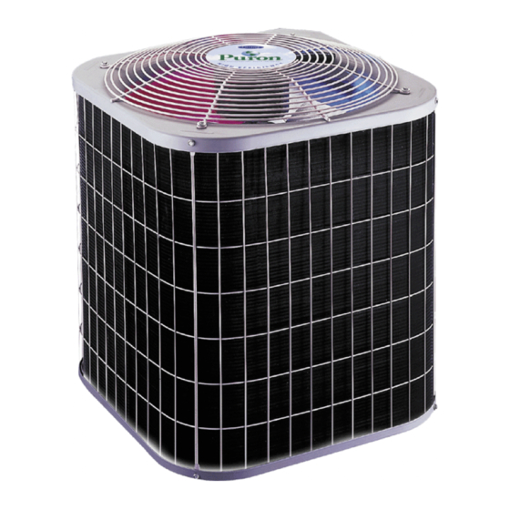
12, 13, 14 SEER Split-System
Air Conditioner with Puron®
Fig. 1—Models 38EZA, 38ETA, 38ESA
.
3. Run refrigerant tubes as directly as possible by avoiding
unnecessary turns and bends.
4. Leave some slack between structure and unit to absorb
vibration.
5. When passing refrigerant tubes through the wall, seal opening
with RTV or other pliable silicon-based caulk. (See Fig. 2.)
6. Avoid direct tubing contact with water pipes, duct work, floor
joists, wall studs, floors, and walls.
7. Do not suspend refrigerant tubing from joists and studs with a
rigid wire or strap which comes in direct contact with tubing.
(See Fig. 2.)
8. Ensure that tubing insulation is pliable and completely sur-
rounds vapor tube.
9. When necessary, use hanger straps which are 1 in. wide and
conform to shape of tubing insulation. (See Fig. 2.)
10. Isolate hanger straps from insulation by using metal sleeves
bent to conform to shape of insulation.
When outdoor unit is connected to factory-approved indoor unit,
outdoor unit contains system refrigerant charge for operation with
indoor unit of the same size when connected by 15 ft of
field-supplied or factory accessory tubing. For proper unit opera-
tion, check refrigerant charge using charging information located
on control box cover and/or in the Check Charge section of this
instruction.
IMPORTANT: Maximum liquid-line size is 3/8-in. O.D. for all
residential applications including long line.
IMPORTANT: Always install the factory-supplied liquid-line fil-
ter drier. If replacing the filter drier, refer to Product Data Digest
for appropriate part number. Obtain replacement filter driers from
your distributor or branch.
Printed in U.S.A.
Form 38ESA-3SI
38EZA, 38ETA, 38ESA
Pg 1
9-02
Replaces: 38ESA-2SI
A99327
Advertisement
Table of Contents

Subscribe to Our Youtube Channel
Related Manuals for Carrier 38ETA


Summary of Contents for Carrier 38ETA
- Page 1 Consult local building codes and National A99327 Electrical Code (NEC) for special requirements. Fig. 1—Models 38EZA, 38ETA, 38ESA Recognize safety information. This is the safety-alert symbol When you see this symbol on the unit and in instructions or 3.
-
Page 2: Installation
→ Step 6—TXV Installation (38ETA and 38ESA Required) wind baffles. Consult the Application Guideline and Service NOTE: All 38ETA and 38ESA units MUST be installed with a Manual — Residential Split-System Air Conditioners and Heat hard shut off Puron® TXV. - Page 3 ⁄ –IN. STRAINER BRASS HEX DISTRIBUTOR PISTON TEFLON SEAL PISTON COPPER TUBE ⁄ –IN. BRASS RING PISTON RETAINER HEX BODY A01164 Fig. 4—AccuRater® Components (38EZA Use) 6. Remove bulb from vapor tube inside cabinet. 7. Braze equalizer stub-tube closed. Use protective barrier as Remove indoor coil piston if unit is to be installed on system necessary to prevent damage to drain pan.
- Page 4 SWEAT CONNECTION 10 O'CLOCK 2 O'CLOCK SENSING BULB To avoid valve damage while brazing, service valves must be wrapped in a heat-sink material such as a wet cloth. STRAP Service valves are closed from factory and ready for brazing. After wrapping service valve and filter drier with a wet cloth, braze SUCTION TUBE sweat connections using industry accepted methods and materials.
- Page 5 LIQUID-LINE FILTER-DRYER CONNECTOR TUBE A99331 Fig. 6—Liquid-Line Filter Drier Table 1—Refrigerant Connections and Recommended Liquid Line and Vapor Tube Diameters (In.) LIQUID VAPOR VAPOR (LONG LINE) UNIT SIZE Connection Diameter Tube Diameter Connection Diameter Tube Diameter Connection Diameter Tube Diameter 018, 024 030, 036 042, 048...
- Page 6 5000 DISCONNECT PER N.E.C. AND/OR 4500 LOCAL CODES 4000 CONTACTOR LEAK IN 3500 SYSTEM 3000 2500 FIELD POWER 2000 WIRING VACUUM TIGHT 1500 BLUE TOO WET 3 PHASE ONLY 1000 TIGHT FIELD GROUND DRY SYSTEM WIRING GROUND A95424 MINUTES A94025 A95424 Fig.
-
Page 7: Sequence Of Operation
Follow these steps to properly start up the system. Step 12—Check Charge 1. After system is evacuated, fully back seat (open) liquid and UNIT CHARGE vapor service valves. Factory charge and charging method are shown on unit informa- 2. Unit is shipped with valve stem(s) front seated (closed) and tion plate. -
Page 8: Care And Maintenance
Table 5—Superheat Charging OUTDOOR EVAPORATOR ENTERING AIR TEMPERATURE (°F WB) TEMP (°F) — — — — — — — — — — — — — — — — — — — — — — — — — — — — —... - Page 9 Table 6—Required Suction-Line Temperature (°F WB) SUPERHEAT SUCTION PRESSURE AT SERVICE PORT (PSIG) TEMP 107.8 112.2 116.8 121.2 126.0 130.8 138.8 140.8 145.8 (°F)
- Page 10 CARRIER CARRIER FA, FB, FC, NON-PROGRAMMABLE NON-PROGRAMMABLE FD, FF, FX SINGLE-STAGE THERMOSTAT THERMOSTAT FAN COIL CONDITIONER MODEL AC FURNACE CONDITIONER MODEL AC 24 VAC HOT 24 VAC HOT 24 VAC COM 24 VAC COM W/W1 HEAT STAGE 1 NOTE 2...
-
Page 11: Wiring Diagram Notes
Fig. 11—Typical 24v Circuit Connections (Continued) WIRING DIAGRAM NOTES: 1. CARRIER THERMOSTAT WIRING DIAGRAMS ARE ONLY ACCURATE FOR MODEL NUMBERS TSTAT _______. 2. WIRING MUST CONFORM TO NEC OR LOCAL CODES. 3. SOME UNITS ARE EQUIPPED WITH PRESSURE SWITCH(ES), TEMPERATURE SWITCH, OR 5-MINUTE COMPRESSOR CYCLE PROTECTION. - Page 12 • Do not use capillary tube coils. • Observe all warnings, cautions, and bold text. Copyright 2002 CARRIER Corp. • 7310 W. Morris St. • Indianapolis, IN 46231 38esa3si Manufacturer reserves the right to discontinue, or change at any time, specifications or designs without notice and without incurring obligations.
Need help?
Do you have a question about the 38ETA and is the answer not in the manual?
Questions and answers