
Related Manuals for Linertec LTS-202N


Summary of Contents for Linertec LTS-202N
- Page 1 TOTAL STATION LTS-200 SERIES LTS-202N LTS-205N INSTRUCTION MANUAL Basic Procedures...
-
Page 4: Table Of Contents
Content Exemption clause ........................3 PRECAUTIONS REGARDING SAFETY ................4 Usage precautions ........................7 1. BASIC OPERATION ......................10 1.1 Names of parts ......................10 1.2 Standard equipment ....................11 1.3 Unpacking and packing ..................... 12 1.4 Removing and attaching the Battery ................. 12 1.5 How to charge the Battery .................. - Page 5 8.3 Entering the mode for initial setting 2 ................ 40 8.4 Entering the mode for initial setting 3 ................ 41 8.5 Entering the mode for initial setting 4 ................ 41 8.6 Entering the mode for initial setting 5 ................ 41 8.7 Example of changing an initial setting content ............
-
Page 6: Exemption Clause
Before using this product, be sure that you have thoroughly read and understood this instruction manual to ensure proper operation. After reading this manual, be sure to keep in a convenient place for easy reference. Exemption clause 1) TI Asahi Co,. Ltd.(TIA) shall not be liable for damage caused by Acts of God, fire, alteration or servicing by unauthorized parties, accident, negligence, misuse, abnormal operating conditions. -
Page 7: Precautions Regarding Safety
PRECAUTIONS REGARDING SAFETY_ Safety precautions (Must be followed) The following items are intended to prevent possible injury to the user or other people and/or damage to the instrument before it occurs. These safety precautions are important to the safe operation of this product and should be observed at all times. Distinctive displays The following displays are used to distinguish precautions by the degree of injury or damage that may result if the precaution is ignored. - Page 8 Never use the telescope to view intense light such as direct sunlight or sunlight reflected through a prism as this may result in loss of sight. Do not disassemble, modify or repair this product as there is a risk of laser radiation. Do not aim the laser beam at a person as it is harmful to the eyes and body.
- Page 9 • Do not touch any fluid which may leak from the battery as there is a risk of chemical burn injury or reaction. • Do not insert or remove the electric plug with wet hands as there is a risk of electric shock. •...
-
Page 10: Usage Precautions
Usage precautions Surveying instruments are high-precision instruments. In order to assure that the LTS-200 series total station which you have purchased will provide long-lasting maximum performance, the precautions in this manual must be followed. Make sure to follow these instructions and use this product properly at all times. [Solar observation] WARNING Never view the sun directly using the telescope as this may result in loss of sight. - Page 11 [Battery & charger] • Do not use any battery or battery charger that is not approved by LINERTEC as it entails a risk of damaging the instrument. • If water should happen to splash on the instrument or the battery, wipe it off immediately and allow it to dry in a dry location.
- Page 12 [Checks and repairs] • Always check the instrument before beginning work and check that the instrument is maintaining the proper level of precision. LINERTEC bears absolutely no responsibility for damages due to survey results obtained from surveys conducted without an initial instrument check.
-
Page 13: Basic Operation
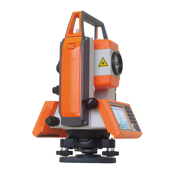
1. BASIC OPERATION 1.1 Names of parts Detachable type Top handle Collimator Focus ring Eyepiece ring Eyepiece Instrument height mark Laser indicator Battery latch Plate vial Battery pack SD & USB cover Telescope tangent screw Display panel Telescope clamp screw Key board Clamp screw Detaching knob... -
Page 14: Standard Equipment
Objective lens Laser plummet Centering knob 1.2 Standard equipment • Instrument • Carrying case • BP04 Battery (2 pcs.) • BC04 Charger • AC Adapter • Power supply cord • Plumb bob • Plummet hook • Hexagonal wrench • Adjusting pin •... -
Page 15: Unpacking And Packing
1.3 Unpacking and packing [Unpacking the Instrument from the case] ① Set the case down gently with the lid facing upwards. ② Open the latches while pressing down on the lock (safety mechanism) and open the lid of the case. ③... -
Page 16: How To Charge The Battery
① The upper part of the battery is pushed. ② Lift up the battery pack and remove it from the instrument. [Attaching the Battery] ① Place the electric contact on the bottom of the battery pack onto the protrusion of the instrument and push the battery pack down into place. 1.5 How to charge the Battery The LTS-200 comes with two lithium-ion rechargeable batteries with a typical operating time between 8(EDM+ETH) to 22hours(ETH only). -
Page 17: External Connections
Description NONE AC cord or AC adapter is not correctly connected Battery is being re-charged GREEN Battery charge is finished. A fully discharged battery will take approximately 2.5 hours to fully charge. Contact a Recycling Center to ensure proper disposal of lithium-ion Batteries. - Page 18 SD cards can be used with the LTS-200 series. This test has been done with only the LINERTEC LTS-200 series Total Station, but no other LINERTEC Total Stations. When using with other LINERTEC Total Stations, please contact us to confirm if it works properly.
-
Page 19: Display And Keyboard
2. DISPLAY AND KEYBOARD 2.1 Display and keyboard Enter key Laser key Power supply key Function key Illumination key ESC key 2.2 Operation keys Description ON/OFF of power supply. [POWER] [ESC] Returns to previous screen or cancels an operation. Turns the illumination of the LCD display and telescope reticle on [ILLU] and off. -
Page 20: Function Keys
2.3 Function keys Display F. Key Description MODE A Pressing this key one time measures the distance in normal [MEAS] mode. Another measurement type can be selected by InitialSetting 2. Pressing this key twice measures the distance in coarse mode. Another measurement type can be selected by initial setting 2. - Page 21 [Other functions] ▽ Moves the cursor to the left. ▽ Moves the cursor to the right. ▽ Moves the cursor up. ▽ Moves the cursor down. [ △ ] Goes back five items on the screen. [ ▽ ] Gose forward five items on the screen. [RETICLE] Changing the reticle illumination when pressing illumination key.
-
Page 22: Alphanumeric Input
2.4 Alphanumeric input The point name is input by the alphanumeric keys as following. Letter under key Letter & figure order to input [@][.][_][-][:][/][0] PQRS [P][Q][R][S][p][q][r][s][1] [T][U][V][t][u][v][2] WXYZ [W][X][Y][Z][w][x][y][z][3] [G][H][I][g][h][i][4] [J][K][L][j][k][l][5] [M][N][O][m][n][o][6] [ ][?][!][_][¯][^][|][&][7] [A][B][C][a][b][c][8] [D][E][F][d][e][f][9] [.][,][:][;][#][(][)] [+/-] [+][-][*][/][%][=][<][>] 2.5 LD POINT, Laser pointer The Laser pointer function turns the laser beam on continuously to become the aiming point so that visual confirmation is possible. -
Page 23: Preparation For Surveying
3. PREPARATION FOR SURVEYING 3.1 Centring and Levelling of the Instrument [Setting up the instrument and the tripod] ① Adjust the tripod legs so that a height suitable for observation is obtained when the instrument is set on the tripod. ②... - Page 24 [For the Shift type laser plummet equipment model] • Turn on the laser plummet function by pushing the [Laser] key and [F4] [PLUM.ADJ] key. • Match the position by the tripod so that the laser mark coincides with the ground mark. •...
-
Page 25: Levelling With Circular Vial
3.3 Levelling with circular vial Tripod is adjusted according to the following points by extending or contracting the legs so that the bubble of the Circular vial goes to the centre of the circle. • Shorten the leg at the side of the bubble or extend the leg opposite of the bubble to position the bubble in the centre of the vial circle. -
Page 26: Eyepiece Adjustment
3.5 Eyepiece adjustment [Eyepiece adjustment] The eyepiece adjustment is performed before target sighting. Vertical line (single) ① Remove the telescope lens cap. Horizontal line ② Point the telescope at a bright object, and rotate the eyepiece ring full counter clockwise. ③... -
Page 27: Target Sighting
3.6 Target sighting [Target sighting by Manual focus] ① Loosen the telescope clamp and horizontal clamp screws. ② Point the telescope at the target using a collimator. ③ Tighten the above two screws. ④ Adjust the eyepiece. ⑤ Look through the telescope and then rotate the Focus ring and stop it where the target can be clearly seen and the target image does not move in relation to reticle even if your eye is vertically and horizontally moved. -
Page 28: Attachment And Detachment Of Tribrach
3.7 Attachment and detachment of tribrach The tribrach of LTS-202N and LTS-205N can be detached from the instrument, if required when replacing the instrument with a prism for example. [Detachment] First loosen the recessed screw with a screwdriver, then rotate the locking knob until the arrow points upward, and lift the instrument up. -
Page 29: Turning The Power On
4. TURNING THE POWER ON 4.1 Turning the power on and off To set power on: To shut down: To turn the power supply off, press the I/O key for more than 1 second and then release it. Power turns OFF. NOTE: The power is automatically turned off after 10 minutes of inactivity (Factory default setting). -
Page 30: Adjusting Illumination Brightness
4.3 Adjusting illumination brightness Press [F5] while holding down the Illumination key to access the screen for adjusting illumination brightness. Pressing the [F1] [ ] will decrease brightness, while pressing the [F2] [ ] will increase brightness. Press [ENT] to exit adjustment mode and return to the previous screen. -
Page 31: Angle Measurement
5. ANGLE MEASUREMENT 5.1 Measuring an angle Aim at the first target, then press [F3] [0 SET] twice in succession to reset the horizontal angle to 0. Aim at the second target, then read the horizontal angle and vertical angle. •... -
Page 32: Holding The Horizontal Angle
• The [F3] [0 SET] cannot reset the vertical angle to 0. • Pressing the [F3] [0 SET] accidentally during measurement does not reset the horizontal angle to 0 unless you press it again. Once the buzzer stops sounding, you can go to the next step. -
Page 33: Displaying The Slope % Of The Vertical Angle
Press [F5] [SELECT] to open the horizontal angle input window. [F5] [CLEAR] is used to clear the values. Press the numeric key as 123.4520. Press the [ENT] key to accept the horizontal angle set to 123° 45' 20" and change the screen. •... -
Page 34: Changing The Horizontal Angle From Clockwise To Counter Clockwise
• The 0% represents the horizontal 0, and +100% and -100% represent 45° up and down slopes respectively. • To return the screen from the slope (%) display to the 360° scale, also take above same steps by entering MODE B. •... -
Page 35: Distance Measurement
6. DISTANCE MEASUREMENT 6.1 Target setting The target mode and its Constant of current setting are shown at the left of the battery mark. For example in case of each Constant 0, Reflectorless (Non-Prism); N 0, Prism; P 0 Pressing [F2] [TARGET] changes the target mode. •... -
Page 36: Distance Measurement
[Distance measurement by reflector sheet mode] Position the Reflector sheet whose reflecting surface faces the aiming line to be approx. right angle when the distance is measured by it. If it is positioned not to be approx. right angle, there is a possibility that correct distance measurement may be impossible by dispersion or reduction of laser beam. - Page 37 the [F1] [MEAS] again terminates both distance measurement and blinking of the “MEAS” text. • Pressing[F5][MODE]and [F1] [DISP] cycles through the sets of display items:“H.angle/H.dst./V.dst.”, “H.angle/V.angle/S.dst.”, and “H.angle/V.angle/H.dst./S.dst./V.dst.” • Pressing the [ESC] or [F2] [TARGET] or [F5] [MODE] during distance measurement stops it.
-
Page 38: Correction Mode
7. CORRECTION MODE 7.1 Changing the target constant Changing the Target Constant can be performed only when the Reflector sheet and Prism Constant setting are “INPUT” in initial setting 1. Example: Prism Constant -25mm setting Press [F4] [CORR] in MODE B. (If the instrument is in MODE A, press [F5] [MODE] to enter MODE B.) Press the [F5] [SELECT] to enable... -
Page 39: Changing The Temperature
• To set the Reflector sheet constant to “0mm” select “0mm” for “SHEET CONST” in “initial setting 1”. • To set the Prism constant to“0mm” or “-30mm” select “0mm” for “PRISM CONST” in “initial setting 1”. • When the “Sheet Constant” has been set to “0mm” in “initial setting 1” and “PRISM CONST”... -
Page 40: Changing The Atmospheric Pressure
Pressing the [ENT] key returns the instrument to MODE A. • The valid range of Temperature input is from -30°C to +60°C. • When “ATM CORR” in “initial setting 1” has been set to “4. NIL”, “*” is displayed to the left of the temperature value on the correction menu screen. -
Page 41: Changing The Ppm Value
Pressing the [ENT] key returns the instrument to MODE A. • The valid range of Pressure input is from 600 to 1120hPa (420 - 840mmHg) . • When “Atmospheric Correction” in “initial setting 1” has been set to “3. NIL”, “*” is displayed to the left of the pressure value on the correction menu screen. - Page 42 Press the [ENT] key to accept the PPM to 31ppm. Pressing the [ENT] key returns the instrument to MODE A. • The valid range of ppm values is from -199 to +199. • Once set, the ppm value is displayed at the centre of the top of the measurement screen. •...
-
Page 43: Initial Setting
8. INITIAL SETTING 8.1 Overview For the LTS-200 series, you can select and save the desired setting for a variety of prescribed instrument conditions, called initial setting. The Initial Setting is saved in five modes, “initial setting 1”, “initial setting 2”, “initial setting 3”, “initial setting 4”, and “initial setting 5”... -
Page 44: Entering The Mode For Initial Setting 3
• Select the item of interest in the same way as in the mode for initial setting 2. 8.4 Entering the mode for initial setting 3 Press the [POWER] key while holding [F3] key down to access the screen for initial setting 3. 8.5 Entering the mode for initial setting 4 Press the [POWER] key while holding [F4] key down to access the screen for initial setting 4. -
Page 45: Example Of Changing An Initial Setting Content
8.7 Example of changing an initial setting content (selection of atmospheric correction) This section describes the operating procedures for selecting “1.ATM CORR” in initial setting 1 as an example of changing an initial setting content. Use this example as a reference when changing other items because it is also applicable to the operating procedures for changing them. -
Page 46: Initial Setting 1
8.8 Initial setting 1 1. Selection of Atmospheric Correction: [ATM CORR] X1.ATM INPUTaXXX Select whether Atmospheric Correction is to be performed 2.ppm INPUT by entering the atmospheric temperature and pressure, 3.NIL by entering ppm value, or by fixing the ppm value to 0 (NIL) not to perform Atmospheric Correction. -
Page 47: Initial Setting 2
8.9 Initial setting 2 1. Selection of the Minimum Distance measurement unit : X1.1mmXXXXXX [EDM MIN DISP] 2.0.1mm More fine angle view is necessary, select 0.1mm, Besides that, select 1mm. X1.1 TIMEXXXXXXX 2. Selection of the Shot count: [SHOT COUNT] 2.3 TIMES Select whether the shot count for Shot distance 3.5 TIMES... - Page 48 9. Selection of Minimum unit of agnle display: [MIN 1.COARSE UNIT ANG.] X2.FINEXXXXXXXXX Select whether to set the minimum angle display mode to “COARSE (5 seconds)” or “FINE (1 second)”. X1.Z.0 XXXXX 9. Selection of Vertical angle style: [V.ANG. STYLE] 2.H.0 Select whether the 0 point for vertical angle is set to be “Z.0”, “H.0”...
-
Page 49: Initial Setting 3
8.10 Initial setting 3 1. Input of date 08/12/24 Set date using [numeric keys]. Year / month / date 00:00:01 2. Input of time Set time using [numeric keys]. Time : minute : second • The date clock is powered by the built-in lithium battery. The lithium battery needs to be replaced in five years. -
Page 50: Initial Setting 4
8.11 Initial setting 4 1. Selection of Temperature unit setting: [TEMP. UNIT] X1.゚ CXXXXXXXXXX Select °C or °F as the unit for Temperature. 2.゚ F 2. Selection of Pressure unit setting: [PRESS UNIT] XXXXX Select hPa (hectopascal), mmHg, inchHg as the unit for 2. - Page 51 X1.NIL XXXXX 3. Selection of Parity: [PARITY BITS] 2.EVEN Select no (NIL) parity bit, even parity or odd parity. 3.ODD X1.1 XaXXXXXX 4. Selection of Stop bits: [STOP BITS] Select the number of stop bits to be used: 1 or 2. 5.
-
Page 52: Accessing The Functions
9. ACCESSING THE FUNCTIONS 9.1 Accessing by help key You can use the [HELP] key to display specific initial setting (such as the prism constant and priority mode). Press the [ILLU]+[ESC] key in MODE A or B. The help menu will then be displayed. Press [F1] [ △ ][F2] [ ▽ ] or [F3] [ ] [F4] [ ] to position the cursor to the desired item. - Page 53 [Instrument setting items] HELP menu list Default Other options TARGET CONST PRISM CONST -30mm 0mm, INPUT SHEET CONST INPUT ATM CORR ATM INPUT ppm INPUT, NIL ATM CORR DISP EDM MIN DISP/QUICK 1mm/OFF 1mm/ON, 0.1mm SHOT COUNT SHOT COUNT 1TIME 3TIMES, 5TIMES, INPUT SHOT INPUT 01TIMES...
-
Page 54: Data Collector
10. DATA COLLECTOR The instrument can communicate directly with a computer through the RS-232c or Bluetooth interface. By use of a data collector you can automate data entry, from the collection of survey data to the transfer of the data to a computer. This is useful in saving time and protecting data integrity. -
Page 55: Circular Vial
Leveling screw to be adjusted. Plate vial Leveling screw to be adjusted. [Adjustments] ① If the bubble of the plate lever moves from the center, bring it half way back to the center by adjusting the leveling screw(s) which is parallel to the plate level. ②... -
Page 56: Vertical Reticle
Turn the bubble adjustment screws with the reticle adjustment pin and put the bubble in the centre of the circle. [Only the detaching type model] Turn the bubble adjustment screws with the reticle adjustment pin and put the bubble in the centre of the circle. -
Page 57: Perpendicularity Of Line Of Sight To Horizontal Axis
Reticle adjusting screws 11.4 Perpendicularity of line of sight to horizontal axis [Checks] ① Position a target Point A at a distance 30m - 50m away from the instrument, and sight it with the telescope. ② Loosen the telescope lock screw and turn the telescope until a point is sighted at a distance roughly equal to that of Point A. -
Page 58: Vertical 0 Point Error
② Using the adjustment pin, rotate the reticle adjustment screws horizontally opposite each other (see preceding page), and move the reticle to sight Point D. ③ Repeat the check and make sure the adjustment is correct. 11.5 Vertical 0 point error Make sure to follow check procedures mentioned below after making adjustments on reticle and perpendicularity of line of sight to horizontal axis. -
Page 59: Offset Constant
A repair engineer does this adjustment. Please contact the LINERTEC dealer. 11.7 Offset constant The offset constant rarely changes. It is recommended, however, that checks be done once or twice a year. The check of the offset constant can be done on a certified base line. It can also be obtained in a simple way as described below. -
Page 60: Beam Axis And Line Of Sight
11.8 Beam axis and line of sight Be sure to check that the beam axis and line of sight are aligned when the adjustments on reticle and perpendicularity of line of sight to horizontal axis are made. [Checks] ① Set the prism at a distance greater than 50m. ②... - Page 61 [Example: Adjustment is necessary] [Example: Adjustment is unnecessary] [Adjustments] At the procedure 4. above, if the “Centre” of laser spot is not within the internal circle (10mm) of the target plate, the adjustment is necessary. Please contact your LINERTEC dealer.
-
Page 62: Appendix
12. APPENDIX 12.1 Warning and Error Messages Warning Meaning What to do Message Out of tilt range Displayed when the instrument is tilted Re-level the instrument. beyond the vertical compensation range Repair is needed if the (±3’) in case automatic compensation is message is displayed selected. -
Page 63: Atmospheric Correction
sighting sharp edge etc. at Reflectorless mode. Li-batt.voltage • The Date Clock is powered by the Have the lithium battery is low. built-in lithium battery. replaced by the dealer • The lithium battery needs to be from whom the instrument replaced in five years. -
Page 64: Hpa And Mmhg Conversion Table
12.3 hPa and mmHg conversion table [Converting from hPa to mmHg] Unit:mmHg 1000 1100 1200 [Converting from mmHg to hPa] Unit:hPa mmHg 1000 1013 1027 1040 1053 1067 1080 1093 1107 1120 1133 1147 1160 1173 1187 1200 1213 1227 1240 1253 1267... - Page 65 [Error table: When hPa (15°C, 1013hPa as standard)] Unit:mm 1200 1100 1013 C° -0.5 -2.6 -5.5 -8.0 -10.5 -13.0 -15.5 -1.8 -4.7 -7.3 -9.9 -12.5 -15.1 -0.9 -4.0 -6.6 -9.3 -12.0 -14.6 -0.0 -3.1 -5.9 -8.6 -11.4 -14.2 -2.2 -5.1 -8.0 -10.8 -13.7...
-
Page 66: Atmospheric Refraction And Earth Curvature Correction
12.5 Atmospheric refraction and earth curvature correction • Atmospheric refraction and earth curvature correction refers to correcting both the bending of the light beam caused by atmospheric refraction and the effect on the height differenTIAl and horizontal distance caused by the earth curvature. •... -
Page 67: Distance Range
12.6 Distance range Generally speaking, the maximum range which can be measured varies considerably depending on the atmospheric conditions. For this reason, the specifications illustrate the values for both good and normal weather conditions. It is extremely difficult to judge when weather conditions are “Good” and when they are “Normal”. -
Page 68: Specifications
12.7 Specifications LTS-202N LTS-205N Model Telescope Image Erect Magnification 30 x Effective aperture 45mm Resolving power 3.0" Field of view 1°30' Minimum focus distance 1.0m Focus Manual Laser Class Visible Laser : Class IIIa ( Reflectorless, sheet ) / Class I ( Prism) Measurement range (Good condition) *3 Reflectorless ... - Page 69 Normal conditions: 20km visibility with slight shimmer Good conditions: 40km visibility with overcast, no heat, no shimmer and moderate wind. EDM measuring time is determined in good conditions. It may takes longer than usual to measure the distance exceeding 2000m in prism mode and 300m in reflectorless mode.
-
Page 70: Notice To The User Of This Product
13. NOTICE TO THE USER OF THIS PRODUCT To assure compliance with the Safety standard 21 CFR, Chapter 1., Subchapter J., the U.S. Bureau of Radiological Health requires the following information to be provided to user.: It can be dangerous to look into the beam with optical equipment such as binoculars and telescopes. -
Page 71: Caution To Maintain The Safety In Compliance With The Standard
C) Maintenance and repair not covered in this manual must be done by an authorized LINERTEC dealer. D) The Laser beam emission by the Distance measurement can be terminated by Pressing [ESC] key. - Page 72 E) Pressing [Laser] key and [F2] [ RED MARK] key can terminate the laser beam emission by the laser pointer. F) The laser beam emission by the laser plummet can be terminated by pressing laser key and [F4] [PLUM.ADJ] key.
-
Page 73: Labelling
13.4 Labelling Aperture label Identification Warning logotype Laser beam is transmitted from this aperture For North America Certification LED is turned on at the time of emission Warning logotype Warning logotype Aperture label Laser beam is transmitted from this aperture... - Page 76 TI Asahi Co., Ltd. International Sales Department 4-3-4 Ueno Iwatsuki-Ku, Saitama-Shi Saitama,339-0073 Japan Tel, +81-48-793-0118 Fax, +81-48-793-0128 E-mail: trade@tilinertec.com LTS200_Basic01A...
Need help?
Do you have a question about the LTS-202N and is the answer not in the manual?
Questions and answers