
Related Manuals for Linertec LTS-200 Series


Summary of Contents for Linertec LTS-200 Series
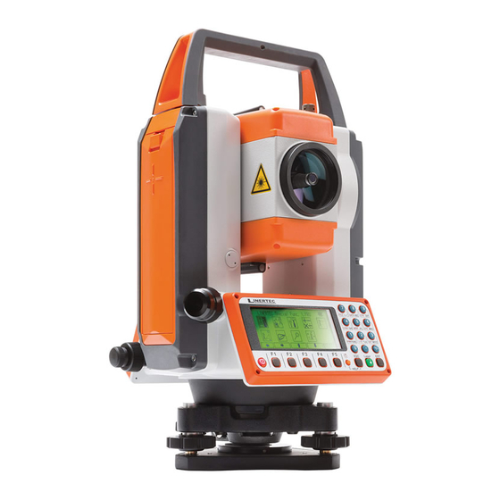
- Page 1 TOTAL STATION LTS-200 SERIES LTS-202N LTS-205N On-Board Application LinertecExpress INSTRUCTION MANUAL - 1 -...
- Page 3 Before using this product, be sure that you have thoroughly read and understood this instruction manual to ensure proper operation. After reading this manual, be sure to keep in a convenient place for easy reference. Exemption clause TI Asahi Co.,Ltd. (TIA) shall not be liable for damage caused by Acts of God, fire, alteration or servicing by unauthorized parties, accident, negligence, misuse, abnormal operating conditions.
-
Page 4: Table Of Contents
DISPLAY AND KEYBOARD....................6 Operation Key........................6 Function Key........................7 1. INTRODUCTION.........................9 1.1 Introduction.........................9 1.2 Before using the LinertecExpress manual..............10 2. ACCESSING LINERTECEXPRESS................12 2.1 How to access LinertecExpress................12 2.2 Allocation of each LinertecExpress Function key..........12 2.3 Typical Function keys of LinertecExpress.............13 3. PROGRAM.........................14 3.1 RDM (Remote Distance Measurement)..............14 3.1.1 PH INPUT.......................15 3.1.2 Reference Point-Target Distance..............15... - Page 5 5.5.12 Both faces meas....................53 5.5.13 Save Mode.....................53 5.5.14 BACKSIGHT SAVE..................53 7.MEASURE..........................81 7.1 Rectangular Coordinates..................81 7.2 Polar Coordinates.....................82 7.3 Rectangular & Polar Coordinates................84 7.4 IH measurement......................86 8. STAKE OUT........................89 8.1 Stake Out........................89 8.2 Point to Line......................94 8.3.1 Three point....................100 8.3.2 Circle radius....................103 9.
- Page 6 All Rights Reserved TI Asahi Co.,Ltd. is a sole proprietor of the LinertecExpress software. The LinertecExpress software and publication or parts thereof, may not be reproduced in any form, by any method, for any purpose. TI Asahi Co.,Ltd. makes no warranty, expressed or implied, including but not limited to any implied warranties or merchantability or fitness for a particular purpose, regarding these materials and makes such materials available.
-
Page 7: Display And Keyboard
DISPLAY AND KEYBOARD • Basic display and keyboard of LTS-200 series are described below, and the function keys of LinertecExpress are described in “2. ACCESSING LINERTECEXPRESS”. Alphanumeric and +/- key Enter Key Laser Key Power Supply Key Function Key Illumination Key... - Page 8 Function Key Moves the cursor to the left. [ ] Moves the cursor to the right. [ ] Moves the cursor up. [ ] Moves the cursor down. [ △ ] Goes back five items on the screen. [ ▽...
- Page 9 Display combination of MODE A or MODE B Function MODE A MODE B MEAS DISP TARGET ANG SET 0 SET HOLD S.FUNC CORR MODE MODE Mode A or Mode B is switched by pressing [F5] [MODE]. • ALPHANUMERIC INPUT The point name etc. is input by the alphanumeric keys as following. Letter &...
-
Page 10: Introduction
Thank you for your first look at LinertecExpress by reading this manual. The LinertecExpress is a user friendly data collection and calculation program for the LINERTEC LTS-200 Series Total Stations. LinertecExpress is developed based on PowerTopo, which is known as a versatile on-board software. -
Page 11: Before Using The Linertecexpress Manual
• Memories in the instrument The LTS-200 series incorporates not only the LinertecExpress surveying programs as the Special Function but also File Manager and Data Transfer Programs. The internal memory of the instrument can store a maximum of 60,000 points of data. - Page 12 “Process type” that takes over the functionality of “LinertecExpress” or “Structure type” that takes over the functionality of our past product in ”Action Method Selection”. The LTS-200 series instrument has a Job name of “LINERTEC” and “COGOPoint” as • its default setting. Each data is stored under “LINERTEC” unless another new Job name is created.
-
Page 13: Accessing Linertecexpress
ACCESSING LINERTECEXPRESS 2.1 How to access LinertecExpress To access the LTS-200 Special Functions of the LinertecExpress, perform the following procedures. Press the [POWER] (ON/OFF) key. The Electronic Vial screeen will comes up. Press Enter Key or Laser Key to proceed to the LTS-200 start-up screen. Then, change to BASE MEASURE screen. -
Page 14: Typical Function Keys Of Linertecexpress
2.3 Typical Function keys of LinertecExpress Following function keys are typical of LinertecExpress and each function key is described for each function in this Manual. Description PAGE Views another function combination. SELECT Selects the Character and moves to next input at PN input etc. ACCEPT Enters the displayed values without new Coordinates value input etc. -
Page 15: Program
3. PROGRAM 3.1 RDM (Remote Distance Measurement) Target 1 Target 2 Ref. P Station With RDM, the Horizontal, Vertical and Slope distance and % of Slope between the Reference point and the Target point are measured. Any Target point can be changed to the new Reference point. -
Page 16: Ph Input
3.1.1 PH INPUT Press [F4] [EDIT] to input the PH, Reference Point Height. 3.1.2 Reference Point-Target Distance Aim at the Reference point and press [F1] [MEAS] to measure the Reference point. It turns to TARGET POINT screen automatically. Aim at the Target 1 and press [F1] [MEAS] to measure a distance. -
Page 17: Rem
Press the [F5] [ENT] to view the TARGET POINT screen. Reference point is changed. Input the new PH and repeat the same procedure as the above. 3.2 REM 3.2.1 General Pictures of Measurement With REM measurement, a prism (Reference point) is set approximately directly below the place to be measured, and by measuring the prism, the height to the target object can be measured. -
Page 18: Vpm
3.3. VPM Virtual plane created by 3 points Coordinates of your aimed point on the vertical plane Vertical plane created by 2 points Azimuth Station Coordinates The Virtual plane includes the Vertical plane. With VPM, the Coordinates on the vertical plane and virtual plane can be obtained by entering the “Station Coordinates and Azimuth”... - Page 19 [LIST] Key All stored points can be displayed as follows by pressing [F2] [LIST]. Press the [F2] [LIST] to view POINT SELECTION FROM THE LIST screen. You can enter Coordinates data by applying the List data. Press [ENT] to open the input window of PN, X, Y, Z and IH value.
- Page 20 Press [ENT] to view the next MEASURE screen. In the same manner, aim at point 2 and press [F1] [ MEAS]. Measured Coordinates are displayed. Press [ENT] to view the COORD. ON THE VIRTUAL PLANE screen. Aim at your desired point and press [ENT]. The Coordinates which you aim at are displayed.
-
Page 21: Communication
4. COMMUNICATION The communication setting and the Input/Output of data are performed by this function. We recommend you not to press any key until data transfer is completed while transfer operation. Notice concerning the unit of data to transfer. Output data (Rect. data & Polar data). Coordinates and Distance data. - Page 22 [Coordinate data] X, Y, and Z coordinate data A 6-digit integer part and a 3-digit fraction part represent coordinate data. [BCC] To detect a data transmission error, BCC is calculated per block and attached to the end of data. [L/F code] use CR/LF BCC is calculated by the following calculation method BCC = ΣA –...
-
Page 23: Text File Read / Write
Press the [2] [COMMUNICATION] of the LinertecExpress to view the TRANSFER MENU screen. 4.1 Text File read / write Text file read/write allows you to input and output format and text data specified recording media. Before taking this procedure, make sure of TextFile Setup (refer to “4.1.3. Text file Setup”). -
Page 24: Reading From Text File
[DATA SAVE PLACE] INTERNAL Save data in the memory of the instrument. Output file can be loaded to PC by connecting a USB (Refer to 4.2 Communication with USB ) SD CARD Save data in the SD card. Output file can be loaded to PC by connecting a USB. - Page 25 Select the format of the file you desire to read and data save place, then press [ENT] [FORMAT SELECTION] (Extension DC1) • (Extension CSV) • ExtCSV (Extension CSV) • [DATA SAVE PLACE] INTERNAL Read the file in the internal memory of the instrument.
- Page 26 The SD cards listed in the following table have been tested by us and • it has been confirmed that the SD cards can be used with the LTS-200 series . This test has been done with only the LINERTEC LTS-200 series Total Station, but no other LINERTEC Total Stations.
-
Page 27: Text File Setup
Regardless of the information mentioned here, take note that not all SDHC cards can be • used with the LTS-200 Total Stations. Test item:The following has been done according to our Test Standards. • ① When data is being sent (by connecting USB), it is necessary to be able to refer to information on the SD card from PC and to operate the file. - Page 28 Press [ENT] to open the selection window. Select each setting and press [ENT]. Press [ACCEPT] to enter when all selections are finished. Factory default setting of 3. SEND POLAR DATA • 1. ROTATION: CW 4.1.3.2 Reading data setting Select the 4. TextFile Setup and press [ENT] to view the TextFile Setup screen.
-
Page 29: Communication With Usb
4.2 Communication with USB By connecting the instrument and PC with USB cable, you can refer to information in the internal memory and SD card. You can use this to transfer the file in the internal memory and SD card to PC or send the file created in the PC to the internal memory or SD card. Connect the instrument and PC by USB cable as follows;... -
Page 30: Data Transfer
Finish USB communication, then return to TRANSFER MENU screen. NOTE: If the Removable Disk doesn’t activate although the USB is connected, click My Computer then double-click Removable disk. CAUTION DAT file in the internal memory is identical with the information in the job file stored in •... -
Page 31: Sending Data
Select the 1. RECEIVE RECT. DATA and press [ENT] to view FORMAT SELECTION screen. Select the DC1 format and press [ENT] to view DATA RCV. CONFIRMATION screen. (Same procedure is performed for CSV format.) Set the PC to be ready to send and press [ENT] to receive the data from the PC. - Page 32 [POLAR DATA] Select the 3. SEND POLAR DATA and press [ENT] to view the FORMAT SELECTION screen. Select DC1 format and press [ENT] to view the DATA SEND. CONFIRMATION screen. (Same procedure is performed for AUX format.) Press [ENT], and set the PC to be ready to receive. 4.3.3 Communication setup The communication parameter is set when stored data is received or sent between the instrument and...
- Page 33 Press [ACCEPT] when all selections are made. DISP.# AXIS: BASIS DIRECT., RIGHT ANGLE, or HEIGHT is selected when • data is transferred between the TS and PC. (cfr. “5.5.2 Coordinate axis definition”) They are used for matching coordinate system between definition in the instrument and definition in the external device when they are different.
- Page 34 Press [ACCEPT] when all selections are made. DISP.# AXIS: BASIS DIRECT, RIGHT ANGLE, or HEIGHT is selected when • data is transferred between the TS and PC. (cfr. “11.2 Coordinate axis definition”) They are used for matching coordinate system between definition in the instrument and definition in the external device when they are different.
- Page 35 6. XON/XOFF: 7. ROTATION:...
-
Page 36: About Datalink Dl-01 Software
4.3.4 About DataLink DL-01 Software DataLink DL-01 Software allows you to send collected data by LTS-200 to other devices, to receive coordinates data, and to convert the resulting files into a number of common formats. a) Recommendation for "PN". It is recommended that “PN” (Point Name) data should consist of less or equal to 4 (one-byte) numeric characters to convert files with DL-01. - Page 37 b-4 Recommended communication settings on LTS-200. Recommended settings for “COMM SETTING SELECTION” on LTS-200 special function is as follows. LTS-200 → PC(DL-01) to “SEND RECT. DATA” 1. BAUD RATE: 1200 2. DATA LENGTH: 3. PARITY BITS: 4. STOP BITS: 5. SIGNAL CONTROL: 6.
- Page 38 For setting “Type of Device” in the “Settings” panel (Menu—“Edit”--”Settings”), select “R-100(PTL) / R-300(PTL)” ,and other setting should be as follows. Please note that these settings should be common with LTS-200's. And if the selection of “Type of Device” is not correct it may result in missing some data. LTS-200 →...
- Page 39 d) Note on converting CSV file. When you attempt to convert CSV file from LTS-200 by DL-01, please note that it may not succeed if CSV data type is not correct. After [CONVERT] button is clicked on DL-01 then “CSV files from PCS/ R-100 (*.*)” is selected for the type of file, “CSV Import Option”...
-
Page 40: Setup
5.SETUP Followings are possible functions and the factory default settings: A language other than English can be selected. Press [ENT] [SETUP] of the LinertecExpress screen to view the FUNCTION SETTING screen. 5.1 ADJUST SETTING Select 1. ADJUST SETTING of the FUNCTION SETTING screen to view the following screen. -
Page 41: [4. Comp Axis]
[4. COMP AXIS] Select the 4. COMP AXIS and press [ENT] to view the following screen. Press the down arrow key to choose and press [ENT] to enter. 5.2 ACTION SETTING Select the 2. ACTION SETTING of the FUNCTION SETTING screen and press [ENT] to view the following screen. - Page 42 [ENT] to enter. [5. TILT DISP UNIT] Select the 6.TILT DISP UNIT and press [ENT] to view the following screen. Press the down arrow key to choose and press [ENT] to enter. [6. LONG RANGE MES.] Select the 7.LONG RANGE MES. and press [ENT] to view the following screen.
-
Page 43: Unit Setting
[ENT] to enter. [12. EDM OFF] Select the 13. EDM OFF and press [ENT] to view the following screen. Press the down arrow key to choose and press [ENT] to enter. [13. ILLU. OFF] Select the 14.ILLU. OFF and press [ENT] to view the following screen. -
Page 44: Communication Setting
[3. DIST. UNIT] Select the 3.DIST. UNIT and press [ENT] to view the following screen. Press the down arrow key to choose and press [ENT] to enter. [4. ANG. UNIT] Select the 4.ANG. UNIT and press [ENT] to view the following screen. Press the down arrow key to choose and press [ENT] to enter. -
Page 45: Language Selection
Recording format to record polar data “HA VA SD” Press [3] [SETUP] of the Linertec screen and press the down arrow key to view the PREFERENCE screen. 5.5.1 Language Selection Select 1. LANGUAGE and press [ENT] to view the LANGUAGE selection window. - Page 46 Select 2. COORD. SYSTEM and press [ENT] to view the coordinate system definition window. Press [ENT] to select and press [F5] [ACCEPT] to enter. Height Basis Direction ( use r difined ) 90° 90° CW CCW 针 (Right Angle) Right Angle Station Point Definition of each selection is as follows.
- Page 47 Item Description Selection Default ex.1 German ex.2 ex.3 Name of the 1st Axis Any name DISP.1 NAME on the screen. (Ex. it is shown 3rd line of the “MEASURE” screen.) Name of the 2nd Any name DISP.2 NAME Axis on the screen. (Ex.
-
Page 48: Input Method Selection
Any name can be defined for all three axes. For the “DISP.# NAME”, it is possible to define same name. However, please note that the same coordinates’ value will be displayed. Three types of axes can be selected for each three axes. - Page 49 1. 10 Key System(ABC/123) These are the standard input method using the Alphanumeric and +/- key. 2. Full template Select each Character by pressing left, right, up and down arrow keys and select each Character by pressing [F5] [SELECT] each time. 3.
-
Page 50: Action Method Selection
5.5.4 Action Method Selection Select 4. ACTION METHOD and press [ENT] to view the following screen. Press the down arrow key to choose and press [ENT] to enter. Process type This input method takes over the functionality of “LinertecExpress”. When this option is selected, the next screen will be shown after inputting necessary items. -
Page 51: Compare Method Selection
1. Cylinder face The Remote measurement is performed on the inner surface of the vertical cylinder as shown left. Cylinder Angle 2. Fixed plane The Remote measurement is performed on the fixed plane, which is perpendicular to the sight of the reference point as shown left. -
Page 52: Request Aiming Selection
When “ALL IN ONE INFO”is selected, all information will be displayed on the result of Stake Out panel. When “LARGE CHARACTER”is selected, result information is shown with two screens and these screens and the Graphics screen can be switched by pressing [SCROLL]. -
Page 53: Elevation Factor
1. PRIM.MAES KEY 1. MEAS. SHOT 2. MEAS. CONT 3. TRACK SHOT 4. TRACK CONT 2. SEC.MEAS KEY 1. TRACK CONT 2. TRACK SHOT 3. MEAS. CONT 4. MEAS. SHOT 3. EDM MIN DISP/QUICK 1. 1mm/OFF 2. -
Page 54: Duplicate Point Check
Cross section of the earth Select 9. Elevation factor and press [ENT] to view the ELEVATION FACTOR selection window. Press [ENT] to select and press [F5] [ACCEPT]. 1. Average Elevation Average (H) = Averaged on-site elevation Input range: -9999.9998 -- +9999.9998m 2. -
Page 55: Meas. Display
5.5.11 Meas. Display This setting allows you to set the order of display when a function of “11. MEAS. DISP” is carried out. When “POLAR DATA” is selected, STATION POINT H.ANGLE SETUP screen appears next to ANG. & DIST. screen. When “RECT. DATA” is selected, MEASURE screen is displayed. -
Page 56: Both Faces Meas
5.5.12 Both faces meas. When “ON” is selected and sighting the BSP (Back Sight Point), you are requested to sight at reverse position as well after normal position. When “OFF” is selected, you can sight only at normal position. 5.5.13 Save Mode If you switch to SAVE MODE, you can change the display when Polar data is displayed. - Page 57 • • Point distance offset Arc distance offset • "COGOPoint" FILE The LTS-200 series automatically creates “COGOPoint” file. In the file, the following 14 coordinates to be used in COGO function, are recorded. Station Point End Point Coordinates Point 1...
- Page 58 which is carried out later. If you wish to input the initial value in advance, edit it by using “VIEW&EDIT of EDIT THE RECT. DATA. (Refer to “5.3 Edit the Data”). 6.1.1 Inverse EP : end point SP : Station Point From the given two point Coordinates, the Direction angle and distance are calculated.
- Page 59 [LIST] key • All stored points can be displayed as follows by pressing [F2] [LIST]. Press [F2] [LIST] to view POINT SELECTION FROM THE LIST screen. Press [ENT] to open the SP input screen. Input your desired Point Name by pressing keys, and press [ENT] to open the X coordinate input screen.
- Page 60 After PC input, press [ENT] or F5[ACCEPT] to viwe the EP screen. Input the PN, X, Y, Z Coordinates and PC name of the End point. Press [ENT] to view the RESULT OF INVERSE screen. C. Another End point Coordinates input Input the PN, X, Y, Z Coordinates and PC name of another End point, and another inverse result can be performed.
- Page 61 6.1.2 Point Coordinates Bearing Distance First Point A point Coordinates is calculated from a known point Coordinates and the Distance and Horizontal angle of the Second point. Input: Coordinates of a known point, Distance and Horizontal angle of the Second point Output: Coordinates of the Second point From the LinertecExpress screen, press 4 to view the CALCULATION screen.
- Page 62 Press [ENT] to open the X coordinate input screen. Press [ENT] to open the Y coordinate input screen. Press [ENT] to open the Z coordinate input screen. Press [ENT] to open the PN input screen. Press [ENT] to open the PC input screen.
- Page 63 Input your desired PC by pressing keys, and press [ENT] to view DI screen. Input your desired value and press [ENT] to open the H. ANGLE input window. Input your desired value to view the RESULT OF COORD. CALCULATE screen. The Second point Coordinates are displayed by plus or minus from the known Coordinates.
- Page 64 Input your desired value and press [ENT] to open the H. ANGLE input window. Input your desired value to view the RESULT OF COORD. CALCULATE screen. The Second point Coordinates are displayed by plus or minus from the known Coordinates. Press [ENT] to view the following screen.
- Page 65 Press [ENT] to view the following screen. The PN, X, Y, Z and PC are viewed and can be edited. If all items are OK, press [F5] [ACCEPT] to save them. 6.1.3 Circle Radius Center P Radius The Center point and radius of the circle drawn by three points are calculated by this function.
- Page 66 Select 1.COGO and press [ENT] to view the COGO screen. Select the 3. CIRCLE RADIUS and press [ENT] to view CIRCLE RADIUS screen. Select 1. P1 and press [ENT] to view P1 screen. Input PN (Point Name), X, Y, Z, and PC (Point Code) of P1 point or import from the memory of rectangular coordinate as P1 by [F2] [LIST].
- Page 67 6.1.4 Line-Arc intersection Point 1 Point 2 Center P Radius Two intersection points of one line and circle are calculated by this function. The line is drawn by SP and EP. The circle is drawn by center point and radius. You can store two possible intersection points.
- Page 68 Select 1. SP and press [ENT] to view SP screen. Input PN (Point Name), X, Y, Z, and PC (Point Code) of SP point or import from the memory of rectangular coordinate as SP by [F2] [LIST]. If you finish the input of SP value, press [F5] [ACCEPT].Then you go to EP input screen.
- Page 69 6.1.5 Line-Line intersection Intersection Point The intersection point of two lines drawn by given four points is calculated by this Function. Input: First line: S1 (Start point) and E1 (End Point) Second line: S2 (Start point) and E2 (End Point) Output: Intersection point between the two lines From the LinertecExpress screen, press 4 to view the CALCULATION screen.
- Page 70 Select 1.S1 and press [ENT] to view S1 screen. Input PN (Point Name), X, Y, Z, and PC (Point Code) of S1 point or import from the memory of rectangular coordinate as S1 by [F2] [LIST]. If you finish the input of S1 value, press [F5] [ACCEPT].
- Page 71 6.1.6 Arc-Arc intersection Center 2 Radius2 Point 1 Arc 2 Center 1 Point 2 Radius 1 Arc 1 Two intersection points of two arcs drawn by each center point and radius are calculated. You can store two possible intersection points. Input: Arc 1: Center point and Radius Arc 2: Center point and Rradius...
- Page 72 Select 1. C1 and press [ENT] to view C1 screen. C1 (Center 1) point is Center point of Arc 1. Input PN (Point Name), X, Y, Z, and PC (Point Code) of C1 point or import from the memory of rectangular coordinate as C1 by [F2] [LIST]. If you finish the input of C1 value, press [F5] [ACCEPT].Then you go to R1 input screen.
- Page 73 If all items are OK, press [F5] [ACCEPT] to save them. 6.1.7 DISTANCE OFFSET Offset P offset New Point Distance Offset P Offset distance of new point to the line and distance of Start point to new point are displayed. Also New Point on the line is calculated by point of start, end, and offset. You can store the New Point.
- Page 74 Select the 7. DISTANCE OFFSET and press [ENT] to view DISTANCE OFFSET screen. Select 1. SP and press [ENT] to view SP screen. Input PN (Point Name), X, Y, Z, and PC (Point Code) of SP point or import from the memory of rectangular coordinate as SP by [F2] [LIST].
- Page 75 6.1.8 Point Distance Offset New Offset Point New Point New Offset Point New offset point is calculated by inputting distance from Start point and Offset from line. Input: line: Start point and End Point Distance from Start point (DI) Offset from the line (OD) (moving in the direction from start point to End Point, right is positive, left is negative) Output: New Point From the LinertecExpress screen, press 4 to view the...
- Page 76 Select 1. SP and press [ENT] to view SP screen. Input PN (Point Name), X, Y, Z, and PC (Point Code) of SP point or import from the memory of rectangular coordinate as SP by [F2] [LIST]. If you finish the input of SP value, press [F5] [ACCEPT].Then you go to EP input screen.
- Page 77 The PN, X, Y, Z and PC are viewed and can be edited. If all items are OK, press [F5] [ACCEPT] to save them. 6.1.9 Arc distance offset New Offset Point New Point New Offset Point Offset point from the arc is calculated. Input: arc: Start point, End Point and Radius (R) Distance along arc from Start point (DI)
- Page 78 Select the 9. ARC DISTANCE OFFSET and press [ENT] to view ARC DISTANCE OFFSET screen. Select 1. SP and press [ENT] to view SP screen. Input PN (Point Name), X, Y, Z, and PC (Point Code) of SP point or import from the memory of rectangular coordinate as SP by [F2] [LIST].
- Page 79 Press [F5] [ACCEPT] to save it。 The PN, X, Y, Z and PC are viewed and can be edited. If all items are OK, press [F5] [ACCEPT] to save them.
- Page 80 6.2 2D SURFACE 3D CONTOUR SURFACE SURFACE 2D CONTOUR ● STORED POINT This function calculates the 2D and 3D contour of a polygon and the 2D surface of the area defined by the polygon. You define the polygon by selecting points and LinertecExpress then calculates contour and 2D surface.
- Page 81 Select 2. 2D SURFACE and press [ENT] to view POINT SELECTION FROM THE LIST screen. If you press [F5] [PAGE], you can see another screen. You select the order of points, which define the polygon at this screen. How to select points of polygon [ENT] Key:...
- Page 83 NOTE: [F1] [ORDER] key Press [F1] [ORDER] to confirm order of selected points after you finished the selection. If you finish point selection of a polygon, press [F1] [ACCEPT] to calculate. The result of calculation is displayed as follows. Press [ENT] or [ESC] to return to POINT SELECTION FROM THE LIST screen. You change a selection, and you can calculate it again.
- Page 84 Please insert English translation of 道路軟件 here.
-
Page 85: Measure
Backsight P. Coordinates Azimuth Station Point Coordinates 7.1 Rectangular Coordinates Press 7 [MEAS] of the LINERTEC to view the MEASURE METHOD SELECTION screen. Select 1.RECTANGULAR COORD. and press [ENT] to view the STATION POINT SETUP screen. Press [F1] [Meas] to measure and display the coordinate. -
Page 86: Polar Coordinates
No survey data is saved when no PN is input. Press [F4] [EDIT] to edit the PN, Point Name, PH, Prism Height and PC, Point Code. Input your desired Point Name, Prism Height and Point Code. Press [F5] [ACCEPT] if the current PN, PH and PC are acceptable. - Page 87 Press 7 [MEAS] of the LINERTEC to view the MEASURE METHOD SELECTION screen. Select 2. POLAR COORD. and press [ENT] to view the STATION POINT SETUP screen. 。 Press [F1] [Meas] to measure and display the coordinate. Press [F2] [SAVE] to save the measured data.
-
Page 88: Rectangular & Polar Coordinates
The target type can be selected by pressing [F2] [TARGET]. 7.3 Rectangular & Polar Coordinates Rectangular Data and Polar Data can be stored at the same time in this function. Press 7 [MEAS] of the LINERTEC and press [ENT]to view the MEASURE METHOD SELECTION screen. - Page 89 If Point Code exists, you can easily select them from the list or edit one of them after pressing [ENT]. For using PointCodeList, please refer to“10.3.2 Point Code”. Pressing [F5][PAGE] switches the screen as follows; MEAS DISPLAY : RECT. MEAS DISPLAY : POLAR Station Point setup can be changed by pressing [F3] [STATION].
- Page 90 For example, change 1.PRIM. MEAS KEY (MEAS) to TRACK SHOT or TRACK CONT if you want to use tracking measurement with PRIM MEAS KEY (MEAS). The target type can be selected by pressing [F2] [TARGET]. Coordinates display and Angle & Distance display 1) Press [F5] [PAGE] twice.
-
Page 91: Ih Measurement
This function is to measure IH based on known point The IH value measured here will be set as an initial value of IH to be used on each function. Press 7 [MEAS] of the LINERTEC and press [ENT]to view the MEASURE METHOD SELECTION screen. - Page 92 Caution 90 ゚ New point New point FIG 1 FIG 2 As illustrated in Fig. 1, it is optimal to choose the known points P1 and P3. The instrument should be set up in such a manner so that the angle between P1 and P3 becomes 90°.
-
Page 93: Stake Out
Stake Out Point Station Point Press [F4] [FUNCTION] of the LinertecExpress screen to view the“LINERTEC FUNCTION” screen. Select 1.STAKE OUT and press[ENT] or [select] to view the “STAKEOUT METHOD SELECTION” screen. Select 1.STAKE OUT and press [ENT] to input the IH, press [ENT] to view the STATION POINT SETUP screen. - Page 94 Press [ESC] to view STATION POINT H.ANGLE SETUP screen. Input the H. angle by pressing [F2] [INPUT], [F3] [0SET] and [F4] [HOLD] or Backsight Coordinates by pressing [F5] [BSP]. Pressing [F2] [INPUT] Input any horizontal angle. Pressing [F5] [BSP] The information for Back Ssight Point is obtained. Press [ENT] to finalize the input.
- Page 95 To display all information at once, To display information with larger select “ALL IN ONE INFO.” character, select “LARGE CHARACTER”. Press [F3] [DISP] to view another screen. Press [F3] [SCROLL] to view another screen. Press [F1] [NEXT] to view another screen.
- Page 96 Press [F5] [PAGE] to view another screen. Press [F5] [PAGE] to view another screen. Press [F2] [DEV.] key, dx, dy, dz change to deviation in meter. Press [F2] [DEV.] key again, return to dx, dy, dz. If you select “LARGE CHARACTER”, the information is shown with four screens and these screens and the Graphics screen can be switched by [F4] [DRAW].
- Page 97 Press [F5] [PAGE] to view another screen. Press [F1] [DISP] to change graphic view. [Point Name] Station Point DEVIATION Measurement Point Design Point [DEVIATION Information] Display the distance and direction from point P to Point O F(Forward) / B(Back) Forward/Backwards L(Left) / R(Right) Left/Right U(UP) / D(Down)
-
Page 98: Point To Line
Press the [F4] [NEXT] to carry out staking out for the next point. Press the [F5] [PAGE] to view the MEASURE screen. 8.2 Point to Line Int. P Stake Out Point : P Station Point You have to select the point A and B. The distance between the two points A and B has to be at least 1m. - Page 99 Open the PN, X, Y, Z, IH and PC input window and input each. Press [ESC] to view the STATION POINT H. ANGLE SETUP screen. Input the H. angle by pressing [F2] [INPUT], [F3] [0SET] and [F4] [HOLD] or Backsight Coordinates by pressing [F5] [BSP]. Press [ENT] to enter Multiple Orientation.
- Page 100 Distance between Point A and B. This is always positive. A -> B P -> A - B Distance between Int. P and P. If P is on the right side of A-B, the value is positive if P is on the left side of A-B, the value is negative. In case of the below drawing, P is on the right side for A-B , P->A-B is negative.
- Page 101 Press [F3] [ADVANCE] to display the ADVANCE screen. Select [1.EQUAL DISTANCE], enter the following screen. Input the divided distance. The divided point's coordinate can be calculated, and displayed. Press the ACCEPT key, the data will be saved, and return to the measure screen. Coordinates will be calculated from A to B in the order of input distance.
- Page 102 Input Distance Calculated Point Select [2.EQUALLY DIVIDE LINE], enter the following screen. Input the divided pieces. The divided point's coordinate can be calculated, and displayed. Press the ACCEPT key, the data will be saved, and return to the measure screen. Coordinates are calculated to be divided by the number you put from A to B Refer to the following drawing.
- Page 103 Calculated Point 8.3 Point to Arc Press [F4] [FUNCTION] of the LinertecExpress screen to view the“LINERTEC FUNCTION” screen. Select STATION and press[ENT] or [select] to view the “STATION” screen. Select 3. POINT TO ARC and press [ENT] to view POINT TO ARC screen.
-
Page 104: Three Point
When point P is inside the circle, the figures of the distance between SOP and ARC is shown as a negative (-) figure 8.3.1 Three point Stake Out Point : P Station Point Input three points to make a circle, obtain the distance from the Stake Out Point to the circumference. - Page 105 Select 1. THREE POINT and press [ENT] to view the STATION POINT SETUP screen. Open the PN, X, Y, Z, IH and PC input window and input each. Save the data by pressing [F1] [SAVE]. Press [ESC] to view STATION POINT H.ANGLE SETUP screen.
- Page 106 After you are finished with the input, press [F1] [SAVE] or [F5] [ACCEPT] to display the measurement screen. Sight the target, Press [F1] [MEAS] to measure the distance. From the measurement results, the distance from the target to the circumference is displayed. Press [F3] [P.
-
Page 107: Circle Radius
8.3.2 Circle radius Radius Stake Out Point : P Station Point Input center coordinate of the circle and radius to make a circle, then obtain the distance from the Stake Out Point to the circumference. Select“2.CIRCLE RADIUS”,Press [ENT] to view“STATION POINT SETTING” screen. Open the PN, X, Y, Z, IH and PC input window and input each. - Page 108 After you finish sighting the reference point, press [ENT] to go to next screen. Input coordinates of the center point and radius to make a circle. After you are finished with input, press [ENT] to display the measurement screen. Sight the target, Press [F1] [MEAS] to measure the distance. From the measurement results, the distance from the target to the circumference will be displayed.
-
Page 109: File Manager
9.1 Information of the remaining memory availability Press [ENT] to view INFORMATION screen. The remaining memory availability and a JOB Name LINERTEC are viewed on the screen. The Job name “LINERTEC” and “COGOPoint” are a default setting. NOTE: Data being used in COGO will be updated in “COGOPoint” file from time to time. -
Page 110: Selection Of A Job Name
9.3 Selection of a Job Name Select 3. SELECT by pressing the down arrow key. 9.4 Deletion of a Job Name If TOKYO is selected, deletion confirmation screen is viewed. Select [F1] DELETE. Press [ENT] to delete or [ESC] to abort. 9.5 All Clear Select [F1] Clear. -
Page 111: View And Edit
10. VIEW AND EDIT Editing of the stored data is possible by this Function. Three menu items are available: EDIT THE RECT. DATA Edit recorded Rect. Data. • : • EDIT THE POLAR DATA : Edit recorded Polar Data POINT CODE LIST Create and edit PointCodeList •... -
Page 112: Edit The Data
Input the PN, X, Y, Z and PC. Press [ENT] to save them. Press [F2] [LIST] to view the saved points. The first line of the screen shows now displayed point and the total number of points. Press [F1] [DELETE] to delete your desired point. Press [F2] [FIND PN] to find your desired point by the PN input. -
Page 113: Point Code List
Your desired points are deleted and found as described above. After selecting desired point with arrow key, press [ENT] to view the POLAR. DATA EDIT screen to edit. 10.3 Point Code List Select 3. POINT CODE LIST and press [ENT] to view the POINT CODE LIST screen. - Page 114 Please note, that the newly entered PointCode on the instrument is not added to the PointCodeList that is stored in the memory. In this case, edit “PointCodeList.csv” separately. Contents of“PointCodeList.csv”: 1,,PointCodeList, 31,,1,ABC,,,, 31,,2,DEF,,,, 31,,3,GHI,,,, 31,,4,JKL,,,, 31,,5,MNO,,,, 31,,6,PQR,,,, 31,,7,STU,,,, 31,,8,VW,,,, 31,,9,XYZ,,,, Format of the “PointCodeList”...
-
Page 115: Pointcode Create
10.3.2 PointCode Create Press [ENT] to view the PointCode Create screen. Press [ENT] to view and input the PC. After input, press [F1] [SAVE] to save the values. 10.3.3 PointCode Edit Select 2. PointCode Edit and press [ENT] to view the PointCodeList screen. -
Page 116: Free Stationing
First, input the height of the instrument (IH). 11.1 Station setup [By Rectangular Coordinates] Press [F4] [FUNCTION] of the LinertecExpress to view the “LINERTEC FUNCTION” screen.Select[STATION]and press [ENT] or[SELECT] to view the STATION screen. Select 1.RECTANGULAR COORD. and press... -
Page 117: Coordinates, X, Y, Z, Ih, And Pc Input
Press[ENT]to view 1.X, 2.Y, 3.Z, 4.PN ,5.PC. 11.1.1 Coordinates, X, Y, Z, IH, and PC input It goes to 1. X coordinate automatically. Press [ENT] to view the X coordinate input screen. Input your desired X coordinate value by pressing keys. -
Page 118: Point Selection From The List
After pressing [ENT], you can edit Point Code data. Input your desired PC name by pressing keys, and press [ENT] to view next screen. 11.1.2 Point selection from the list Inputting coordinate information can be done manually and also by calling known points. Press [F2] [LIST] on STATION POINT SETUP screen to display POINT SELECTION FROM THE LIST screen. - Page 119 NOTE: Searching a point by adding “* ” to the initial of the key word enables you to list point data with PN including a string after “*” For instance, if you need to search a point including “P1” in PN, input “*P1” in the key word, then press [ENT].
-
Page 120: Station Orientation
11.1.3 Station Orientation Press the [F5] [ACCEPT] to view the STATION POINT H.ANGLE SETUP screen. Please note, that the rotation of the “H.angle” depends on the rotation setting of “Coordinate axis definition”. Input the H.angle by pressing [F2] [INPUT], [F3] [0SET] and [F4] [HOLD] or Reference Point Coordinates by pressing [F5] [BSP]. -
Page 121: Multiple Orientation
The measured value to be displayed is the average of measured values measured in normal and reverse position. 11.1.4 Multiple Orientation Aim at the reference point , then press [ENT] to enter Multiple Orientation. Pressing [F1] [NO] of “ADD Ref. Point screen immediately takes you to STATION screen. -
Page 122: Station Setup [By Polar Coordinates]
11.2 Station setup [By Polar Coordinates] The same Point Name of the plural polar points can be saved. Press [F4] [FUNCTION] of the LinertecExpress screen to view the “LINERTEC FUNCTION” screen. Select[STATION]and press [ENT] or[SELECT] to view the STATION screen. -
Page 123: Station Orientation
Whichever you select PROCESS TYPE or STRUCTURE TYPE, Pressing [SAVE] or [ACCEPT] proceeds to next screen Input the TEMP value. Press [ENT]. Input the PRESS value. Press [ENT]. Input ppm value. Press [ENT]. TEMP, PRESS and ppm input depend on the “Initial setting 1” (ATM INPUT, ppm INPUT, NIL). -
Page 124: Free Stationing
If you want to calculate direction angle, Press [F5][INVERS] to jump to INVERSE function. Input SP as Station Point, EP as Back Sight Point Result angle is set here automatically by pressing [ENT] at RESULT OF INVERSE screen. Press [ENT] after aiming back sight point. Aim at the reference point, then press [ENT] to enter multiple orientation. - Page 125 Press the [F1] [ADD] to view the KNOWN POINT COORD. SETUP screen. Aim at Point 2, 3 and 4. In the same manner, input the values of Point 2, 3 and 4. [F3] [P2 MEAS] button appears on 3 point of ADD/CALC.SELECTION MENU screen.
-
Page 126: Stationing By Two Known Points
for Station setup after pressing [F5] [ACCEPT]. Horizontal angle of the result coordinates will be affected to the Station Point for measuring. DEVIATIONS OF THE POINT: Four points or more are needed to view this. Press [ENT] to view the DEVIATIONS OF THE POINT screen. - Page 127 Press [ENT] to view the ADD/CALC. SELECTION MENU screen. Press [F1] [ADD] to view the KNOWN POINT COORD. SETUP screen. In the same manner, aim at the Point 2. Press [ENT] to open the PN, X, Y, Z, PH and PC input window and input each value.
- Page 128 Press [F4] [COMPARE] to view the RESULT COORD. OF STATIONING screen. NOTE: 90 ゚ New point New point FIG 1 FIG 2 As illustrated in Fig. 1, it is optimal to choose the known points P1 and P3. The instrument should be set up in such a manner so that the angle between P1 and P3 becomes 90°.
Need help?
Do you have a question about the LTS-200 Series and is the answer not in the manual?
Questions and answers