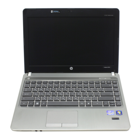
HP ProBook 4430s Maintenance And Service Manual
Notebook pc
Hide thumbs
Also See for ProBook 4430s:
- Maintenance and service manual (153 pages) ,
- Quickspecs (55 pages) ,
- Frequently asked questions manual (25 pages)

Related Manuals for HP ProBook 4430s


Summary of Contents for HP ProBook 4430s
- Page 1 HP ProBook 4430s Notebook PC HP ProBook 4330s Notebook PC Maintenance and Service Guide...
- Page 2 SD Logo is a trademark of its proprietor. The information contained herein is subject to change without notice. The only warranties for HP products and services are set forth in the express warranty statements accompanying such products and services. Nothing herein should be construed as constituting an additional warranty.
- Page 3 Safety warning notice WARNING! To reduce the possibility of heat-related injuries or of overheating the computer, do not place the computer directly on your lap or obstruct the computer air vents. Use the computer only on a hard, flat surface. Do not allow another hard surface, such as an adjoining optional printer, or a soft surface, such as pillows or rugs or clothing, to block airflow.
- Page 4 Safety warning notice...
-
Page 5: Table Of Contents
Table of contents 1 Product description ... 1 2 External component identification ... 8 Display ... 8 Top ... 9 TouchPad ... 9 Lights ... 10 Buttons and fingerprint reader (select models only) ... 12 Keys ... 14 Front ... 16 Left ... - Page 6 Grounding guidelines ... 42 Component replacement procedures ... 45 Service tag ... 45 Battery ... 46 SIM ... 47 Bottom door ... 48 Optical drive ... 49 Hard drive ... 51 Memory modules ... 53 WWAN module ... 55 WLAN/Bluetooth combo card ... 57 Keyboard ...
- Page 7 Using System Diagnostics ... 112 6 Specifications ... 113 Computer specifications ... 113 33.8-cm (13.3-in), HD display specifications ... 114 35.6-cm (14.0-in), HD display specifications ... 115 Hard drive specifications ... 116 Blu-ray BD-R/RE DVD±RW SuperMulti DL Drive ... 117 DVD±RW and CD-RW SuperMulti DL Combo Drive specifications ...
- Page 8 viii...
-
Page 9: Product Description
Product Name Processors Chipset Graphics Panel Description HP ProBook 4430s Notebook PC HP ProBook 4330s Notebook PC Intel® Core™ i7 processor, Dual Core 2620M, 2.70-GHz (Turbo up to 3.40) processor 4-MB L3 cache, 4 threads Intel® Core i5 processors, Dual Core 2540M, 2.60-GHz (Turbo up to 3.30) processor 3-MB L3 cache, 4... - Page 10 ● 4096 (2048 × 2) ● 4096 (4096 × 1) ● 3072 (2048 + 1024) ● 2048 (2048 × 1) Supports 9.5-mm or 7-mm, 6.35-cm (2.50-in) SATA hard drives with HP DriveGuard Customer-accessible 4430s 4330s (UMA) (UMA) √ √ √...
- Page 11 Category Description Supports the following drives: ● 750-GB, 7200-rpm ● 500-GB, 7200-rpm ● 320-GB, 7200-rpm ● 250-GB, 7200-rpm ● 640-GB, 5400-rpm ● 500-GB, 5400-rpm ● 320-GB, 5400-rpm ● 250-GB, 5400-rpm Fixed optical drives Supports the following 12.7-mm SATA optical drives: ●...
- Page 12 Category External media card Ports Keyboard/pointing devices Chapter 1 Product description Description Supports the following WLAN formats: ● Ralink 802.11 b/g/n 1×1 ● Realtek 802.11 b/g/n 1×1 ● Atheros 802.11 b/g/n +BT Combo ● Ralink 802.11 a/b/g/n +BT Combo ● Realtek 802.11 b/g/n +BT Combo ●...
- Page 13 Category Description Touchpad includes: supports 2-way scroll with legend, taps enabled by default, 2-finger scrolling and zoom enabled by default Power requirements Smart AC adapter with localized cable plug support (3-wire plug with ground pin): 65-W 9-cell, 93-Wh Li-ion battery 6-cell, 55-Wh Li-ion battery 6-cell, 47-Wh Li-ion battery Security...
- Page 14 Category Chapter 1 Product description Description Windows 7 Professional 64 with Microsoft Office 2010 Home & Business Windows 7 Professional 64 with Microsoft Office 2010 Professional Windows 7 Home Premium 32 with Microsoft Office 2010 Starter EDGI Windows 7 Home Premium 32 with Microsoft Office 2010 Starter Windows 7 Home Premium 32 with Microsoft Office 2010 Personal Windows 7 Home Premium 32 with Microsoft Office 2010 Home &...
- Page 15 Category Description Web-only support: Windows XP Professional Certified: Microsoft WHQL Serviceability End-user replaceable parts: AC adapter Battery (system) Hard drive Memory module Optical drive WLAN module WWAN module, SIM Keyboard 4430s 4330s (UMA) (UMA) √ √ √ √ √ √ √...
-
Page 16: External Component Identification
External component identification Display Component Speakers (2) Internal display switch WWAN antennas (2)* (select models only) WLAN antennas (2)* Internal microphone(s) (1 or 2 depending on model) Chapter 2 External component identification Description Produce sound. Turns off the display or initiates Sleep if the display is closed while the power is on. -
Page 17: Top
Component Webcam light (select models only) Webcam (select models only) *The antennas are not visible from the outside of the computer. For optimal transmission, keep the areas immediately around the antennas free from obstructions. To see wireless regulatory notices, refer to the section of the Regulatory, Safety, and Environmental Notices that applies to your country or region. -
Page 18: Lights
Lights Component TouchPad light Caps lock light Power light Chapter 2 External component identification Description ● Amber: The TouchPad is off. ● Off: The TouchPad is on. ● White: Caps lock is on. ● Off: Caps lock is off. ● On: The computer is on. - Page 19 Blinking: When the QuickWeb button is pressed, the light blinks 5 times, and then the default Web browser opens. NOTE: To use HP QuickWeb when the computer is off, HP QuickWeb must be enabled in Computer Setup ● White: An integrated wireless device, such as a wireless local area network (WLAN) device and/or a Bluetooth®...
-
Page 20: Buttons And Fingerprint Reader (Select Models Only)
To learn more about your power settings: ● Windows 7—Select Start > Control Panel > System and Security > Power Options. ● Windows Vista—Select Start > Control Panel > System and Maintenance > Power Options ● Or refer to the HP Notebook Reference Guide. - Page 21 Web browser. NOTE: For more information, refer to “HP QuickWeb” in this guide and to the HP QuickWeb software Help. If your computer does not have HP QuickWeb software, the button does not perform any action or function.
-
Page 22: Keys
Keys NOTE: Refer to the illustration that most closely matches your computer. Component Function keys num lk Start key Embedded numeric keypad keys Menu key Chapter 2 External component identification Description Displays system information when pressed in combination with the key. - Page 23 Component Function keys num lk Integrated numeric keypad Start key Menu key Description Displays system information when pressed in combination with the key. Execute frequently used system functions when pressed in combination with the key. Enables/disables the embedded numeric keypad when pressed in combination with the key.
-
Page 24: Front
Chapter 2 External component identification Description ● White: The hard drive or optical drive is being accessed. ● Amber: HP 3D DriveGuard has temporarily parked the hard drive. Supports the following digital card formats: ● Memory Stick Pro ● Memory Stick Duo Pro ●... -
Page 25: Left
Left Component Security cable slot AC adapter light Power connector Vent External monitor port RJ-45 (network) jack Description Attaches an optional security cable to the computer. NOTE: The security cable is designed to act as a deterrent, but it may not prevent the computer from being mishandled or stolen. -
Page 26: Right
Component HDMI port ExpressCard slot SuperSpeed 3.0 USB port (10) USB port Right Component USB ports (2) RJ-11 (modem) jack (select models only) Optical drive Optical drive light Optical drive eject button Chapter 2 External component identification Description Connects an optional video or audio device, such as a high- definition television, or any compatible digital or audio component. -
Page 27: Bottom
Bottom Component Battery and access cover release latches Battery bay SIM slot Vents (2) Access door Description Release the battery from the battery bay, and the access cover from the computer. Holds the battery. Contains a wireless subscriber identity module (SIM) (select models only). -
Page 28: Illustrated Parts Catalog
Illustrated parts catalog Service tag When ordering parts or requesting information, provide the computer serial number and model description provided on the service tag. ● Product name (1). This is the product name affixed to the front of the computer. ●... -
Page 29: Computer Major Components
Computer major components Computer major components... - Page 30 33.8-cm (13.3-inch) HD, BrightView, with webcam ● 33.8-cm (13.3-inch) HD, anti-glare, with webcam and WWAN ● 33.8-cm (13.3-inch) HD, BrightView, with webcam and WWAN For use in HP ProBook 4430s models: ● 35.6-cm (14.0-inch), anti-glare, without webcam ● 35.6-cm (14.0-inch), anti-glare, with webcam ●...
- Page 31 Item Description Atheros AR9002WB-1NGB 802.11b/g/n 1x1 WiFi and Bluetooth 2.1+EDR Combo Adapter for use in Afghanistan, Albania, Algeria, Andorra, Angola, Antigua and Barbuda, Argentina, Armenia, Aruba, Australia, Austria, Azerbaijan, Bahamas, Bahrain, Bangladesh, Barbados, Belarus, Belgium, Belize, Benin, Bermuda, Bhutan, Bolivia, Bosnia and Herzegovina, Botswana, Brazil, the British Virgin Islands, Brunei, Bulgaria, Burkina Faso, Burundi, Cambodia, Cameroon, Canada, Cape Verde, the Cayman Islands, Central African Republic, Chad, Chile, People's Republic of China, Colombia, Comoros, Congo, Costa Rica,...
- Page 32 Item Description Ralink 5390GN 802.11b/g/n 1x1 WiFi Adapter for use in Afghanistan, Albania, Algeria, Andorra, Angola, Antigua and Barbuda, Argentina, Armenia, Aruba, Australia, Austria, Azerbaijan, Bahamas, Bahrain, Baltics, Bangladesh, Barbados, Belarus, Belgium, Belize, Benin, Bermuda, Bhutan, Bolivia, Bosnia and Herzegovina, Botswana, Brazil, the British Virgin Islands, Brunei, Bulgaria, Burkina Faso, Burundi, Cambodia, Cameroon, Canada, Cape Verde, the Cayman Islands, Central African Republic, Chad, Chile, People's Republic of China, Colombia, Comoros, Congo, Costa Rica, Croatia, Cyprus, the Czech Republic,...
- Page 33 Item Description Realtek 8188GN 802.11b/g/n 1x1 WiFi Adapter for use in Afghanistan, Albania, Algeria, Andorra, Angola, Antigua and Barbuda, Argentina, Armenia, Aruba, Australia, Austria, Azerbaijan, Bahamas, Bahrain, Baltics, Bangladesh, Barbados, Belarus, Belgium, Belize, Benin, Bermuda, Bhutan, Bolivia, Bosnia and Herzegovina, Botswana, Brazil, the British Virgin Islands, Brunei, Bulgaria, Burkina Faso, Burundi, Cambodia, Cameroon, Canada, Cape Verde, the Cayman Islands, Central African Republic, Chad, Chile, People's Republic of China, Colombia, Comoros, Congo, Costa Rica, Croatia, Cyprus, the Czech Republic,...
- Page 34 Item Description 2540M, 2.6-GHz (turbo up to 3.3-GHz) processor 3-MB L3 cache (includes phase change material (PCM)) 2520M, 2.5-GHz (turbo up to 3.2-GHz) processor 3-MB L3 cache (includes phase change material (PCM)) 2410M, 2.3-GHz (turbo up to 2.9-GHz) processor 3-MB L3 cache Intel Core i3 processors, Dual Core 2310M, 2.1-GHz processor 3-MB L3 cache (includes thermal grease) Intel Celeron processor, Dual Core...
- Page 35 Item Description 250-GB, 7200-rpm 250-GB, 5400-rpm (22) Bottom door (23) Battery, Li-ion 9-cell (93 WHr, 2.8 Ah) 6-cell (55 WHr, 2.8 Ah) 6-cell (47 WHr, 2.2 Ah) Spare part number 635225-001 622641-001 646341-001 633809-001 628668-001 633805-001 Computer major components...
-
Page 36: Display Components
Item Description Display bezel For use with HP ProBook 4330 models with a webcam For use with HP ProBook 4330 models without a webcam For use with HP ProBook 4430 models with a webcam For use with HP ProBook 4430 models without a webcam... - Page 37 WLAN antennas WWAN antennas (10) Display enclosure For use in HP ProBook 4330s models For use in HP ProBook 4430s models Kensington lock bracket (not illustrated) For use in 4330s models For use in 4430s models Spare part number 646355-001...
-
Page 38: Plastics Kit
Plastics Kit Item Description Plastics Kit RJ-11 holder Secure Digital card protective insert ExpressCard slot protective insert Optical drive protective insert Chapter 3 Illustrated parts catalog Spare part number 646373-001... -
Page 39: Cable Kit
Cable Kit Item Description Cable Kit: Battery connector cable Power connector cable RJ-11 connector cable Mass storage devices Description Optical drives Blu-ray BD-R/RE DVD±RW SuperMulti DL Drive Blu-ray ROM DVD±RW SuperMulti DL Drive DVD±RW and CD-RW SuperMulti DL Combo Drive with LightScribe DVD-ROM Drive Hard drives 750-GB, 7200-rpm... -
Page 40: Miscellaneous Parts
Miscellaneous parts Description AC adapters 65-W AC adapter 65-W AC adapter for use in India 90-W AC adapter 90-W AC adapter for use in India Power cords: For use in Argentina For use in Brazil For use in Denmark For use in Europe, the Middle East, and Africa For use in Israel For use in Italy For use in South Africa... - Page 41 Spare part Description number 490371-081 Power cord for use in Denmark 490371-111 Power cord for use in Switzerland 490371-201 Power cord for use in Thailand 490371-202 Power cord for use in Brazil 490371-AR1 Power cord for use in South Africa 490371-BB1 Power cord for use in Israel 490371-D01...
- Page 42 90-W AC adapter 609947-001 90-W AC adapter for use in India 609948-001 65-W AC adapter for use in India 612600-001 HP lc2010 HSPA Mobile Broadband Module 621565-001 2-GB memory module (PC3-10600, 1333-MHz, DDR3) 621569-001 4-GB memory module (PC3-10600, 1333-MHz, DDR3) 622641-001...
- Page 43 Spare part Description number 630703-001 Ralink 5390GN 802.11b/g/n 1x1 WiFi Adapter for use in Afghanistan, Albania, Algeria, Andorra, Angola, Antigua and Barbuda, Argentina, Armenia, Aruba, Australia, Austria, Azerbaijan, Bahamas, Bahrain, Baltics, Bangladesh, Barbados, Belarus, Belgium, Belize, Benin, Bermuda, Bhutan, Bolivia, Bosnia and Herzegovina, Botswana, Brazil, the British Virgin Islands, Brunei, Bulgaria, Burkina Faso, Burundi, Cambodia, Cameroon, Canada, Cape Verde, the Cayman Islands, Central African Republic, Chad, Chile, People's Republic of China, Colombia, Comoros, Congo, Costa Rica, Croatia, Cyprus, the Czech Republic,...
- Page 44 750-GB, 7200-rpm hard drive 633805-001 6-cell, 47 WHr, 2.2 Ah Li-ion battery 633809-001 9-cell, 93 WHr, 2.8 Ah Li-ion battery 634400-001 HP un2430 EV-DO/HSPA Mobile Broadband Module 634925-001 500-GB, 7200-rpm hard drive 634932-001 500-GB, 5400-rpm hard drive 635225-001 250-GB, 7200-rpm hard drive 638037-001 Intel Core i3 processor, 2310M, 2.1-GHz, 3-MB L3 cache (includes thermal material)
- Page 45 646343-001 Display bezel for use with HP ProBook 4330s models with a webcam 646344-001 Display bezel for use with HP ProBook 4430s models without a webcam 646345-001 Display bezel for use with HP ProBook 4430s models with a webcam 646346-001...
- Page 46 Spare part Description number 646365-161 Keyboard for use in models in Latin America 646365-171 Keyboard for use in models in Saudi Arabia 646365-201 Keyboard for use in models in Brazil 646365-211 Keyboard for use in models Hungary 646365-251 Keyboard for use in models in Russia 646365-261 Keyboard for use in models in Bulgaria 646365-281...
- Page 47 Spare part Description number 646992-001 35.6-cm (14.0-inch) display assembly, anti-glare, with webcam 646993-001 35.6-cm (14.0-inch) display assembly, BrightView, without webcam 646994-001 35.6-cm (14.0-inch) display assembly, BrightView, with webcam 646995-001 33.8-cm (13.3-inch) display assembly, HD, anti-glare, without webcam 646996-001 33.8-cm (13.3-inch) display assembly, HD, anti-glare, with webcam 646997-001 33.8-cm (13.3-inch) display assembly, HD, BrightView, without webcam 646998-001...
-
Page 48: Removal And Replacement Procedures
Removal and replacement procedures Preliminary replacement requirements Tools required You will need the following tools to complete the removal and replacement procedures: ● Flat-bladed screwdriver ● Phillips P0 and P1 screwdrivers ● Torx T8 screwdriver Service considerations The following sections include some of the considerations that you must keep in mind during disassembly and assembly procedures. -
Page 49: Cables And Connectors
Cables and connectors CAUTION: When servicing the computer, be sure that cables are placed in their proper locations during the reassembly process. Improper cable placement can damage the computer. Cables must be handled with extreme care to avoid damage. Apply only the tension required to unseat or seat the cables during removal and insertion. -
Page 50: Grounding Guidelines
Grounding guidelines Electrostatic discharge damage Electronic components are sensitive to electrostatic discharge (ESD). Circuitry design and structure determine the degree of sensitivity. Networks built into many integrated circuits provide some protection, but in many cases, ESD contains enough power to alter device parameters or melt silicon junctions. -
Page 51: Packaging And Transporting Guidelines
Packaging and transporting guidelines Follow these grounding guidelines when packaging and transporting equipment: ● To avoid hand contact, transport products in static-safe tubes, bags, or boxes. ● Protect ESD-sensitive parts and assemblies with conductive or approved containers or packaging. ● Keep ESD-sensitive parts in their containers until the parts arrive at static-free workstations. -
Page 52: Equipment Guidelines
Equipment guidelines Grounding equipment must include either a wrist strap or a foot strap at a grounded workstation. ● When seated, wear a wrist strap connected to a grounded system. Wrist straps are flexible straps with a minimum of one megohm ±10% resistance in the ground cords. To provide proper ground, wear a strap snugly against the skin at all times. -
Page 53: Component Replacement Procedures
Component replacement procedures This chapter provides removal and replacement procedures. There are as many as 95 screws and screw locks, in 15 different sizes, that must be removed, replaced, or loosened when servicing the computer. Make special note of each screw and screw lock size and location during removal and replacement. -
Page 54: Battery
Battery Description 9-cell, 93 WHr, 2.8 Ah Li-ion battery 6-cell, 55 WHr, 2.8 Ah Li-ion battery 6-cell, 47 WHr, 2.2 Ah Li-ion battery Before disassembling the computer, follow these steps: Shut down the computer. If you are unsure whether the computer is off or in Hibernation, turn the computer on, and then shut it down through the operating system. -
Page 55: Sim
NOTE: This section applies only to computer models with WWAN capability. NOTE: If there is a SIM inserted in the SIM slot, it must be removed before disassembling the computer. Be sure that the SIM is reinserted in the SIM slot after reassembling the computer. Before removing the SIM, follow these steps: Shut down the computer. -
Page 56: Bottom Door
Bottom door Description Bottom door Before disassembling the computer, follow these steps: Shut down the computer. If you are unsure whether the computer is off or in Hibernation, turn the computer on, and then shut it down through the operating system. Disconnect all external devices connected to the computer. -
Page 57: Optical Drive
Optical drive NOTE: All optical drive spare part kits include an optical drive bezel. Description Blu-ray BD-R/RE DVD±RW SuperMulti DL Drive Blu-ray ROM DVD±RW SuperMulti DL Drive DVD±RW and CD-RW SuperMulti DL Combo Drive with LightScribe DVD-ROM Drive Before removing the optical drive, follow these steps: Shut down the computer. - Page 58 Remove the optical drive (3) from the computer. If it is necessary to replace the optical drive bracket, position the optical drive with the rear toward you. Remove the two Phillips PM2.0×3.0 screws (1) that secure the optical drive bracket to the optical drive.
-
Page 59: Hard Drive
Hard drive NOTE: All hard drive spare part kits include a hard drive bracket and screws. Description 750-GB, 7200-rpm hard drive 640-GB, 5400-rpm hard drive 500-GB, 7200-rpm hard drive 500-GB, 5400-rpm hard drive 320-GB, 7200-rpm hard drive 320-GB, 5400-rpm hard drive 250-GB, 7200-rpm hard drive 250-GB, 5400-rpm hard drive Hard Drive Hardware Kit (includes hard drive bracket, insulator, and screws) - Page 60 Remove the hard drive (3) from the hard drive bay. If it is necessary to replace the hard drive bracket, remove the tape (1) that secures the Mylar cover down onto the bracket, and then lift to open the Mylar cover (2). Remove the two Phillips PM3.0×3.0 hard drive bracket screws (3) from each side of the hard drive (4 total screws).
-
Page 61: Memory Modules
Memory modules NOTE: Primary and expansion memory is installed in a stacked configuration in the bottom of the computer. Description 1-GB (PC3-10600, 1333-MHz, DDR3) 2-GB (PC3-10600, 1333-MHz, DDR3) 4-GB (PC3-10600, 1333-MHz, DDR3) Before removing the memory module, follow these steps: Shut down the computer. - Page 62 Remove the memory module (2) by pulling the module away from the slot at an angle. NOTE: Memory modules are designed with a notch (3) to prevent incorrect insertion into the memory module slot. NOTE: The computer uses two memory sockets. The top socket houses the expansion memory module and is shown in the following image.
-
Page 63: Wwan Module
CAUTION: The WWAN module and the WLAN module are not interchangeable. Description HP lc2010 HSPA Mobile Broadband Module HP un2430 EV-DO/HSPA Mobile Broadband Module Before removing the WWAN module, follow these steps: Shut down the computer. If you are unsure whether the computer is off or in Hibernation, turn the computer on, and then shut it down through the operating system. - Page 64 Remove the WWAN module (3) by pulling the module away from the slot at an angle. NOTE: WWAN modules are designed with a notch (4) to prevent incorrect insertion. Figure 4-1 Removing the WWAN module NOTE: If the WWAN antennas are not connected to the terminals on the WWAN module, the protective sleeves must be installed on the antenna connectors, as shown in the following illustration.
-
Page 65: Wlan/Bluetooth Combo Card
WLAN/Bluetooth combo card The computer uses a card that provides both WLAN and Bluetooth functionality. CAUTION: The WLAN module and the WWAN module are not interchangeable. Description Atheros AR9002WB-1NGB 802.11b/g/n 1x1 WiFi and Bluetooth 2.1+EDR Combo Adapter for use in Afghanistan, Albania, Algeria, Andorra, Angola, Antigua and Barbuda, Argentina, Armenia, Aruba, Australia, Austria, Azerbaijan, Bahamas, Bahrain, Bangladesh, Barbados, Belarus, Belgium, Belize, Benin, Bermuda, Bhutan, Bolivia, Bosnia and Herzegovina, Botswana, Brazil, the British Virgin Islands, Brunei, Bulgaria, Burkina Faso, Burundi, Cambodia, Cameroon,... - Page 66 Description Realtek 8188BC8 802.11a/b/g/n 2x2 WiFi and Bluetooth 3.0+HS Combo Adapter for use in Afghanistan, Albania, Algeria, Andorra, Angola, Antigua and Barbuda, Argentina, Armenia, Aruba, Australia, Austria, Azerbaijan, Bahamas, Bahrain, Baltics, Bangladesh, Barbados, Belarus, Belgium, Belize, Benin, Bermuda, Bhutan, Bolivia, Bosnia and Herzegovina, Botswana, Brazil, the British Virgin Islands, Brunei, Bulgaria, Burkina Faso, Burundi, Cambodia, Cameroon, Canada, Cape Verde, the Cayman Islands, Central African Republic, Chad, Chile, People's Republic of China, Colombia, Comoros, Congo, Costa Rica, Croatia, Cyprus, the Czech Republic, Denmark,...
- Page 67 Description Ralink 8190BC8 802.11b/g/n 2x2 WiFi and Bluetooth 3.0+HS Combo Adapter for use in Afghanistan, Albania, Algeria, Andorra, Angola, Antigua and Barbuda, Argentina, Armenia, Aruba, Australia, Austria, Azerbaijan, Bahamas, Bahrain, Baltics, Bangladesh, Barbados, Belarus, Belgium, Belize, Benin, Bermuda, Bhutan, Bolivia, Bosnia and Herzegovina, Botswana, Brazil, the British Virgin Islands, Brunei, Bulgaria, Burkina Faso, Burundi, Cambodia, Cameroon, Canada, Cape Verde, the Cayman Islands, Central African Republic, Chad, Chile, People's Republic of China, Colombia, Comoros, Congo, Costa Rica, Croatia, Cyprus, the Czech Republic, Denmark,...
- Page 68 Before removing the WLAN module, follow these steps: Shut down the computer. If you are unsure whether the computer is off or in Hibernation, turn the computer on, and then shut it down through the operating system. Disconnect all external devices connected to the computer. Disconnect the power from the computer by first unplugging the power cord from the AC outlet, and then unplugging the AC adapter from the computer.
- Page 69 Remove the WLAN module (3) by pulling the module away from the slot at an angle. NOTE: WLAN modules are designed with a notch (4) to prevent incorrect insertion. NOTE: If the WLAN antennas are not connected to the terminals on the WLAN module, the protective sleeves must be installed on the antenna connectors, as shown in the following illustration.
-
Page 70: Keyboard
Keyboard NOTE: For a detailed list of available keyboards, see Description Keyboard Before removing the keyboard, follow these steps: Shut down the computer. If you are unsure whether the computer is off or in Hibernation, turn the computer on, and then shut it down through the operating system. Disconnect all external devices connected to the computer. - Page 71 Insert a screwdriver or similar tool into the gap near the fan and push to disengage the keyboard. Position the computer right-side up with the front toward you. Open the computer as far as possible. Lift and rotate the keyboard (1) until it rests on the palm rest (2). Component replacement procedures...
- Page 72 Lift the keyboard connector latch (1), and then disconnect the keyboard cable from the system board (2). Remove the keyboard. Reverse this procedure to install the keyboard. Chapter 4 Removal and replacement procedures...
-
Page 73: Fan
Description Before removing the fan, follow these steps: Shut down the computer. If you are unsure whether the computer is off or in Hibernation, turn the computer on, and then shut it down through the operating system. Disconnect all external devices connected to the computer. Disconnect the power from the computer by first unplugging the power cord from the AC outlet, and then unplugging the AC adapter from the computer. - Page 74 Lift the fan out of the computer (3). Reverse this procedure to install the fan. NOTE: To properly ventilate the computer, allow at least a 7.6-cm (3-in) clearance on the left side of the computer. The computer uses an electric fan for ventilation. The fan is controlled by a temperature sensor and is designed to turn on automatically when high temperature conditions exist.
-
Page 75: Heat Sink
Heat sink All heat sink spare part kits include replacement thermal material. Description Heat sink for use in computers with UMA graphics Before removing the heat sink, follow these steps: Shut down the computer. If you are unsure whether the computer is off or in Hibernation, turn the computer on, and then shut it down through the operating system. -
Page 76: Processor
Reverse this procedure to install the heat sink. Processor NOTE: All processor spare part kits include replacement thermal material. Description Intel Core i7 processor, Dual Core 2620M, 2.7-GHz (turbo up to 3.4-GHz) processor with 4-MB L3 cache Intel Core i5 processors, Dual Core 2540M, 2.6-GHz (turbo up to 3.3-GHz) processor with 3-MB L3 cache (includes thermal grease) 2520M, 2.5-GHz (turbo up to 3.2-GHz) processor with 3-MB L3 cache (includes thermal grease) 2410M, 2.3-GHz (turbo up to 2.9-GHz) processor with 3-MB L3 cache... -
Page 77: Top Cover
Remove the fan (see Remove the heat sink (see Remove the processor: Position the computer upside-down with the front toward you. Use a flat-bladed screwdriver to turn the processor locking screw (1) one-half turn counterclockwise until you hear a click. Lift the processor (2) straight up and remove it. - Page 78 Description With a fingerprint reader Without a fingerprint reader Before removing the top cover, follow these steps: Shut down the computer. If you are unsure whether the computer is off or in Hibernation, turn the computer on, and then shut it down through the operating system. Disconnect all external devices connected to the computer.
- Page 79 Remove the following covers and screws that secure the top cover to the computer: (1): 4 rubber screw covers (2): 10 Torx PM2.5×6.0 screws Remove the following screws that secure the top cover to the computer: (1): 3 Phillips PM2.0×3.0 screws from the optical drive bay and left side of the battery bay (2): 2 Phillips PM2.5×2.5 broadhead screws from the battery bay Position the computer upright with the front toward you.
- Page 80 Remove the following cables from the system board: (1): Fingerprint reader cable (2): Touchpad cable Chapter 4 Removal and replacement procedures...
- Page 81 Disconnect the Quick Launch board cable from the system board. Position the computer on its side with the display open. Component replacement procedures...
- Page 82 Insert a screwdriver through the hole in the battery bay and press to disengage the top cover from the computer. Pull up on the top of the top cover (1), pull upward on the left (2) and right sides (3), and then remove the top cover from the computer (4).
- Page 83 Cable routing path – top Cable routing path – bottom Component replacement procedures...
-
Page 84: Rtc Battery
RTC battery Description RTC battery Before removing the RTC battery, follow these steps: Shut down the computer. If you are unsure whether the computer is off or in Hibernation, turn the computer on, and then shut it down through the operating system. Disconnect all external devices connected to the computer. - Page 85 Lift the battery from the system board (2). Reverse this procedure to install the RTC battery. Component replacement procedures...
-
Page 86: Modem Module
Modem module NOTE: The modem module spare part kit does not include a modem module cable. The modem module cable is included in the Cable Kit, spare part number 646369-001. See for more Cable Kit spare part number information. Description Modem module Before removing the modem module, follow these steps: Shut down the computer. - Page 87 Disconnect the modem module (3) from the system board by lifting it straight up. Reverse this procedure to install the modem module. Component replacement procedures...
-
Page 88: Audio Board
Audio board Description Audio board Before removing the audio board, follow these steps: Shut down the computer. If you are unsure whether the computer is off or in Hibernation, turn the computer on, and then shut it down through the operating system. Disconnect all external devices connected to the computer. -
Page 89: Speaker Assembly
Rotate the audio board upward (3) and then remove it from the top cover. Reverse this procedure to install the audio board. Speaker assembly Description Speaker assembly Before removing the speaker assembly, follow these steps: Shut down the computer. If you are unsure whether the computer is off or in Hibernation, turn the computer on, and then shut it down through the operating system. - Page 90 Optical drive (see WLAN module (see WWAN module (see Fan (see Fan on page Heat sink (see Keyboard (see Top cover (see Remove the speaker assembly: Position the computer upside-down with the front toward you. Disconnect the speaker cable from the system board (1). Remove the speaker cable from the routing path (2) built into the computer.
- Page 91 Lift the speaker from the computer (2) while routing the cable through the hole in the chassis (3). Reverse this procedure to install the speaker assembly. Component replacement procedures...
-
Page 92: Rj-11 Jack Cable
RJ-11 jack cable NOTE: The RJ-11 jack cable is included in the Cable Kit, spare part number 646369-001. Before removing the RJ-11 jack cable, follow these steps: Shut down the computer. If you are unsure whether the computer is off or in Hibernation, turn the computer on, and then shut it down through the operating system. - Page 93 Remove the RJ-11 jack from the clip built into the base enclosure (3). Reverse this procedure to install the RJ-11 jack cable. Component replacement procedures...
-
Page 94: Quick Launch Board
Quick Launch board Description Quick Launch board Before removing the Quick Launch board, follow these steps: Shut down the computer. If you are unsure whether the computer is off or in Hibernation, turn the computer on, and then shut it down through the operating system. Disconnect all external devices connected to the computer. - Page 95 Lift the side of the board (3), slide it out from under the tab, and then remove the board from the top cover (4). Remove the Phillips PM2.0×3.0 screw (1) that secures the board to the top cover. Component replacement procedures...
- Page 96 Lift the side of the board (2), slide it out from under the tab, and then remove the board from the top cover (3). Reverse this procedure to install the Quick Launch board. Chapter 4 Removal and replacement procedures...
-
Page 97: Usb Board
USB board Description USB 2.0 board Before removing the USB board, follow these steps: Shut down the computer. If you are unsure whether the computer is off or in Hibernation, turn the computer on, and then shut it down through the operating system. Disconnect all external devices connected to the computer. -
Page 98: System Board
Lift the board straight up out of the computer (4) Reverse this procedure to install the USB board. System board NOTE: All system board spare part kits include replacement thermal material. Description System boards for use in all countries and regions except for Russia and the People's Republic of China: For use in UMA models with WWAN For use UMA models without WWAN... - Page 99 Before removing the system board, follow these steps: Shut down the computer. If you are unsure whether the computer is off or in Hibernation, turn the computer on, and then shut it down through the operating system. Disconnect all external devices connected to the computer. Disconnect the power from the computer by first unplugging the power cord from the AC outlet, and then unplugging the AC adapter from the computer.
- Page 100 Disconnect the display cable (1) and webcam cable (2) from the system board. Remove the two Phillips PM2.5×4.0 screws (1) that secure the system board to the base enclosure. Lift the optical drive connector latch (2), and then disconnect the optical drive cable (3). Chapter 4 Removal and replacement procedures...
- Page 101 Lift the system board up at an angle (4) to gain access to the cables underneath. On the bottom of the system board, disconnect the battery connector cable (1) from the system board. Disconnect the smaller power cable (2) and the larger power cable (3) from the system board. Lift the system board out of the computer (4).
-
Page 102: Card Reader Board
Card reader board Description Card reader board Before removing the card reader board, follow these steps: Shut down the computer. If you are unsure whether the computer is off or in Hibernation, turn the computer on, and then shut it down through the operating system. Disconnect all external devices connected to the computer. - Page 103 Pull the card reader board downward (2) to disconnect it from the system board connector, and then remove it from the system board. Reverse this procedure to install the card reader board. Component replacement procedures...
-
Page 104: Power Cable
Power cable The power cable is included in the Cable Kit, spare part number 646369-001. Before removing the power cable, follow these steps: Shut down the computer. If you are unsure whether the computer is off or in Hibernation, turn the computer on, and then shut it down through the operating system. - Page 105 Lift the power cable assembly from the computer (2). Reverse this procedure to install the power cable. Component replacement procedures...
-
Page 106: Optical Drive Connector
Optical drive connector Description Optical drive connector Before removing the optical drive connector, follow these steps: Shut down the computer. If you are unsure whether the computer is off or in Hibernation, turn the computer on, and then shut it down through the operating system. Disconnect all external devices connected to the computer. - Page 107 Lift the optical drive connector from the computer (2). Reverse this procedure to install the optical drive connector. Component replacement procedures...
-
Page 108: Display Assembly
33.8-cm (13.3-inch) HD, BrightView, with webcam ● 33.8-cm (13.3-inch) HD, Anti-glare, with webcam and WWAN ● 33.8-cm (13.3-inch) HD, BrightView, with webcam and WWAN For use in HP ProBook 4430s models: ● 35.6-cm (14.0-inch), Anti-glare, without webcam ● 35.6-cm (14.0-inch), Anti-glare, with webcam ●... - Page 109 Modem module (see Modem module on page Keyboard (see Keyboard on page Top cover (see Top cover on page Remove the display assembly: Position the computer upright with the front toward you. Open the computer as far as possible. If necessary, disconnect the display cable (1) and webcam cable (2) from the system board. Remove the two Phillips PM2.5×4.0 screws (1) that secure the security bracket to the computer, and then lift the security bracket from the computer (2).
- Page 110 Lift the display assembly straight up and remove it (5). CAUTION: When installing the display assembly, be sure that the wireless antenna cables are routed and arranged properly. Failure to properly route the antennas can result in degradation of the computer's WLAN and WWAN performance.
- Page 111 To replace the display bezel, remove the two rubber screw covers (1) and the two Phillips PM2.5×4.0 screws (2) in the bottom corners of the display bezel. Flex the top (3) of the bezel, the inside edges of the left and right sides (4), and then the bottom (5) of the bezel until it disengages from the display enclosure.
- Page 112 If it is necessary to replace the webcam module (shown in the following image) or microphone module from the display enclosure, disconnect the cable from the module (1), and then gently pull the module away from the double-sided tape on the display enclosure (2). The webcam module is available using spare part number 642795-001.
- Page 113 Disconnect the display panel cable from the back of the display panel by lifting the tape over the connector (1), and then disconnecting the cable from the panel (2). The display cable is available using spare part number 605766-001. If it is necessary to replace the display hinges, remove the three Phillips PM2.0×3.0 screws (1) that secure each display hinge to the display panel.
- Page 114 Remove the display hinges (2). Display hinges are available using spare part number 646354-001. If you need to remove the WLAN or WWAN antennas, lift the WLAN antenna cables (1) or WWAN antenna cables (2) from the clips and routing paths (3) built into the display enclosure. The WLAN antennas are available using spare part number 646352-001, and the WWAN antennas are available using spare part number 646353-001.
- Page 115 To remove the display cable (1) or webcam cable (2) from the display enclosure, remove the cable from the clips (3) and routing paths in the display enclosure. The display cable is available using spare part number 605766-001. The webcam cable is available using spare part number 646275-001.
-
Page 116: Computer Setup (Bios) And System Diagnostics
Computer Setup (BIOS) and System Diagnostics Using Computer Setup Computer Setup, or Basic Input/Output System (BIOS), controls communication between all the input and output devices on the system (such as disk drives, display, keyboard, mouse, and printer). Computer Setup includes settings for the types of devices installed, the startup sequence of the computer, and the amount of system and extended memory. -
Page 117: Restoring Factory Settings In Computer Setup
NOTE: You can use either a pointing device (TouchPad, pointing stick, or USB mouse) or the keyboard to navigate and make selections in Computer Setup. Press to enter Computer Setup. To exit Computer Setup menus, choose one of the following methods: ●... -
Page 118: Updating The Bios
Updated versions of the BIOS may be available on the HP Web site. Most BIOS updates on the HP Web site are packaged in compressed files called SoftPaqs. Some download packages contain a file named Readme.txt, which contains information regarding installing and troubleshooting the file. -
Page 119: Downloading A Bios Update
Downloading a BIOS update CAUTION: To reduce the risk of damage to the computer or an unsuccessful installation, download and install a BIOS update only when the computer is connected to reliable external power using the AC adapter. Do not download or install a BIOS update while the computer is running on battery power, docked in an optional docking device, or connected to an optional power source. -
Page 120: Using System Diagnostics
● Battery test—This test analyzes the condition of the battery. If the battery fails the test, contact HP Customer Support to report the issue and purchase a replacement battery. You can also view system information and error logs in the System Diagnostics window. -
Page 121: Specifications
Specifications Computer specifications Dimensions Length Width Height (front to rear) Weight (equipped with optical drive, 1 SODIMM, hard drive, WLAN module, 6 cell battery) Input power Operating voltage Operating current Temperature Operating (not writing to optical disc) Operating (writing to optical disc) Nonoperating Relative humidity Operating... -
Page 122: 33.8-Cm (13.3-In), Hd Display Specifications
Operating Nonoperating NOTE: Applicable product safety standards specify thermal limits for plastic surfaces. The computer operates well within this range of temperatures. 33.8-cm (13.3-in), HD display specifications Active diagonal size Resolution Active area Surface treatment Contrast ratio Response time Brightness Viewing angle Backlight Luminance uniformity @ 13 points... -
Page 123: 35.6-Cm (14.0-In), Hd Display Specifications
35.6-cm (14.0-in), HD display specifications Active diagonal size Resolution Active area Surface treatment Contrast ratio Response time Brightness Viewing angle Backlight Luminance uniformity @ 13 points Lifetime (1/2 luminance) Color coordinate (white) Color tolerance (W, R, G, B) Color gamut Metric U.S. -
Page 124: Hard Drive Specifications
Hard drive specifications Dimensions Height Width Weight Interface type Transfer rate Security Seek times (typical read, including setting) Single track Average Maximum Logical blocks Disc rotational speed Operating temperature *1 GB = 1 billion bytes when referring to hard drive storage capacity. Actual accessible capacity is less. Actual drive specifications may differ slightly. -
Page 125: Blu-Ray Bd-R/Re Dvd±Rw Supermulti Dl Drive
Blu-ray BD-R/RE DVD±RW SuperMulti DL Drive Applicable disc Access time Random Maximum Media Capacity (read) Maximum Media Capacity (write) Data transfer rate 24X CD-ROM 8X DVD 2X BD-ROM 16X CD-R 16X CD-RW 8X DVD+R 6X DVD+RW 8X DVD-R 6X DVD-RW 4X DVD+R Dual Layer 4X DVD-R Dual Layer 5X DVD-RAM... -
Page 126: Dvd±Rw And Cd-Rw Supermulti Dl Combo Drive Specifications
DVD±RW and CD-RW SuperMulti DL Combo Drive specifications Applicable disc Center hole diameter Disc diameter Standard disc Mini disc Disc thickness Track pitch Access time Random Full stroke Audio output level Cache buffer Data transfer rate 24X CD-ROM 8X DVD-ROM 24X CD-R 16X CD-RW 8X DVD+R... -
Page 127: Blu-Ray Rom Dvd±Rw Supermulti Dl Drive
Blu-ray ROM DVD±RW SuperMulti DL Drive Applicable disc Access time Random Cache buffer Data transfer rate 24X CD-ROM 8X DVD 24X CD-R 16X CD-RW 8X DVD+R 4X DVD+RW 8X DVD-R 4X DVD-RW 2.4X DVD+R(9) 5X DVD-RAM 1X BD-ROM 1X BD-R read 1X BD-RE read Transfer mode Read:... -
Page 128: Dvd-Rom Drive Specifications
DVD-ROM Drive specifications Applicable disc Center hole diameter Disc diameter Standard disc Mini disc Disc thickness Track pitch Access time Random Full stroke Audio output level Cache buffer Data transfer rate CD-R (24X) CD-RW (10X) CD-ROM (24X) DVD (8X) Multiword DMA mode 2 Startup time Stop time Chapter 6 Specifications... -
Page 129: Specification Information In Device Manager
Specification information in Device Manager Device Manager allows you to view and control the hardware attached to the computer, as well as provides hardware specification information. You can also add hardware or modify device configurations using Device Manager. NOTE: Windows 7 and Windows Vista include the User Account Control feature to improve the security of your computer. -
Page 130: Backup And Recovery
Recovering information using recovery tools NOTE: For detailed instructions, perform a search for these topics in Help and Support. In case of system instability, HP recommends that you print the recovery procedures and save them for later use. NOTE: Windows includes the User Account Control feature to improve the security of your computer. -
Page 131: Backing Up Your Information
Backing up your information Recovery after a system failure is as good as your most recent backup. You should create system repair discs (select models only) by using the installed optical drive (select models only) or an optional external optical drive, and your initial backup immediately after software setup. As you add new software and data files, you should continue to back up your system on a regular basis to maintain a reasonably current backup. -
Page 132: Using The Windows Recovery Tools
Recovery disc (both purchased separately). For additional information, refer to 7 operating system DVD (purchased separately) on page If the Windows partition and the HP Recovery partition are listed, restart the computer, and then press before the Windows operating system loads. -
Page 133: Using A Windows 7 Operating System Dvd (Purchased Separately)
To recover the original hard drive image using f11: If possible, back up all personal files. If possible, check for the presence of the HP Recovery partition: click Start, right-click Computer, click Manage, and then click Disk Management. NOTE: If the HP Recovery partition is not listed, you must recover your operating system and programs using the Windows 7 operating system DVD and the Driver Recovery disc (both purchased separately). -
Page 134: Windows Vista
NOTE: For detailed instructions, perform a search for these topics in Help and Support. NOTE: In case of system instability, HP recommends that you print the recovery procedures and save them for later use. NOTE: Windows® includes the User Account Control feature to improve the security of your computer. -
Page 135: Performing A Recovery
NOTE: DVDs and DVDs with double-layer (DL) support store more information than CDs, so using them for backup reduces the number of recovery discs required. ● When backing up to discs, number each disc before inserting it into the optical drive of the computer. -
Page 136: Using F11 Recovery Tools
Recovery discs have been included for computers that do not have a partition. Use these discs to recover your operating system and software. To check for the presence of a recovery partition, select Start > Computer. If the partition is present, an HP Recovery drive is listed in the Hard Disk Drives section of the window. -
Page 137: Using A Windows Vista Operating System Dvd (Purchased Separately)
Follow the on-screen instructions. Using a Windows Vista operating system DVD (purchased separately) To order a Windows Vista operating system DVD, go to http://www.hp.com/support, select your country or region, and follow the on-screen instructions. You can also order the DVD by calling technical support. -
Page 138: Power Cord Set Requirements
Power cord set requirements The wide range input feature of the computer permits it to operate from any line voltage from 100 to 120 volts AC, or from 220 to 240 volts AC. The 3-conductor power cord set included with the computer meets the requirements for use in the country or region where the equipment is purchased. -
Page 139: Requirements For Specific Countries And Regions
Requirements for specific countries and regions Country/region Australia Austria Belgium Canada Denmark Finland France Germany Italy Japan The Netherlands Norway The People's Republic of China South Korea Sweden Switzerland Taiwan The United Kingdom The United States The flexible cord must be Type HO5VV-F, 3-conductor, 1.0-mm² conductor size. Power cord set fittings (appliance coupler and wall plug) must bear the certification mark of the agency responsible for evaluation in the country or region where it will be used. -
Page 140: Recycling
NOTE: Materials Disposal. This HP product contains mercury in the backlight in the display assembly that might require special handling at end-of-life. Disposal of mercury may be regulated because of environmental considerations. For disposal or recycling information, contact your local authorities, or see the Electronic Industries Alliance (EIA) Web site at http://www.eiae.org. - Page 141 Perform the following steps to disassemble the display assembly: Remove all screw covers (1) and screws (2) that secure the display bezel to the display assembly. Lift up and out on the left and right inside edges (1) and the top and bottom inside edges (2) of the display bezel until the bezel disengages from the display assembly.
- Page 142 Disconnect all display panel cables (1) from the display inverter and remove the inverter (2). Remove all screws (1) that secure the display panel assembly to the display enclosure. Remove the display panel assembly (2) from the display enclosure. Position the display panel assembly upside-down. Remove all screws that secure the display panel frame to the display panel.
- Page 143 Remove the display panel frame (2) from the display panel. Remove the screws (1) that secure the backlight cover to the display panel. Lift the top edge of the backlight cover (2) and swing it outward. Remove the backlight cover. Position the display panel right-side up.
- Page 144 Remove the backlight cables (1) from the clip (2) in the display panel. Position the display panel upside-down. WARNING! backlight to avoid damaging this component and causing exposure to the mercury. Remove the backlight frame from the display panel. Chapter 9 Recycling The backlight contains mercury.
- Page 145 Remove the backlight from the backlight frame. Disconnect the display panel cable (1) from the LCD panel. Remove the screws (2) that secure the LCD panel to the display rear panel. Release the LCD panel (3) from the display rear panel. Release the tape (4) that secures the LCD panel to the display rear panel.
-
Page 146: Index
Index AC adapter light 17 AC adapter, spare part numbers 32, 34 access cover release latches 19 antennas disconnecting 55, 60 audio board removal 80 spare part number 22, 39, 80 audio, product description 3 audio-in (microphone) jack 16 audio-out (headphone) jack 16 Backup and Restore 123 Backup and Restore Center 126, base enclosure, spare part... - Page 147 spare part number 26, 31, 39, 49 specifications 120 DVD±RW and CD-RW SuperMulti DL Combo Drive with LightScribe precautions 41 removal 49 spare part number 26, 31, 39, 49 electrostatic discharge 42 embedded numeric keypad, identifying 14 esc key, identifying 14, 15 Ethernet, product description 3 ExpressCard slot insert, illustrated illustrated 30...
- Page 148 ports external monitor 17 HDMI 18 product description 4 USB 18 power button, identifying 12 power cable removal 96 spare part number 96 power connector cable, illustrated 31 power connector, identifying 17 power cord set requirements 130 spare part numbers 32 power light 10 power requirements, product description 5...
- Page 149 webcam 9 product description 3 spare part number 29, 36 webcam light, identifying 9 webcam, identifying 9 Windows 7 operating system DVD 125 Windows Backup and Restore Windows Vista operating system DVD 129 wireless antennas disconnecting 55, 60 wireless antennas, identifying 8 wireless button, identifying 13 wireless light 11 wireless, product description 3...
Need help?
Do you have a question about the ProBook 4430s and is the answer not in the manual?
Questions and answers