
Subscribe to Our Youtube Channel
Related Manuals for NexSens Technology CB-650

Summary of Contents for NexSens Technology CB-650
- Page 1 CB-650 Data Buoy User Guide Last Revision: 27 June 2022 Date Generated: 1 July 2022 Copyright © 2022 NexSens Technology, Inc.
-
Page 2: Table Of Contents
Table of Contents 1. General CB-650 Data Buoy Overview Key Components and Definitions Key Specifications CB-Series Data Buoy Planning & Precautions 2. Buoy Assembly Using NexSens Electronics in CB-Series Data Buoys Data Loggers Battery Packs Installing User-Supplied Electronics in CB-Series Data Buoys... - Page 3 Connecting Mooring Hardware Deployment Single-Point Mooring Deployment Two-Point and Three-Point Mooring Deployment 4. Troubleshooting and Maintenance Verify Battery Voltage of a CB-Series Buoy Replace a Battery in a CB-Series Data Buoy Battery Removal New Battery Installation Test a CB-Series Buoy Solar Tower Data Buoy Storage Requirements 5.
-
Page 4: General
Data Well – The waterproof compartment located in the center of the buoy hull for placement of system electronics such as batteries and data loggers. On the CB-650 model, the data well has a 10.3” (26.2 cm) diameter and 21.5″ (54.6 cm) height. - Page 5 For users supplying their own electronics, the CB-650 is delivered as an open platform with empty data well or with battery only. A data well top plate can be supplied in one of three ways: 1. A standard CB-PTL Pass Through Lid for passing of instrument cables through gland fittings 2.
-
Page 6: Key Specifications
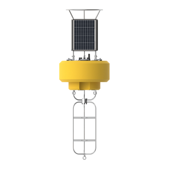
CB-650 buoy frame with instrument cage installed. Key Specifications The key specifications of the CB-650 buoy are given below: Hull Outer Diameter: 38.0” (96.5cm) Hull Height: 22.0” (55.9cm) Data Well Inner Diameter: 10.3” (26.2cm) Data Well Height: 21.5″ (54.6cm) Pass-Through Hole Diameter: 4.0″... -
Page 7: Cb-Series Data Buoy Planning & Precautions
CB-Series Data Buoy Planning & Precautions Buoy deployments are usually complex operations that involve many elements including sensors, data loggers, mounting hardware and mooring equipment. Careful planning is essential to the success of a buoy project, not only for system operation and data collection but also to ensure the project personnel’s safety and minimize the risk of damage to expensive system components. - Page 8 limited to, working on/near water and lifting of heavy equipment. Important factors to consider for personnel safety are: Use of safety equipment (i.e., life jackets, gloves, steel toed boots, etc.,) Proper lifting and mooring techniques Awareness of on-site and surrounding weather conditions and advisories Despite careful planning, unforeseen situations are always still a possibility.
-
Page 9: Buoy Assembly
Series data buoys with data well and solar charging (model CB-150 and larger) X2-CBMC Buoy-Mounted Data Logger – lid-mounted package with wet-mate connectors for use on CB-Series data buoys in challenging environments such as offshore, typical on model CB-650 and larger X2-SDL data logger. -
Page 10: Battery Packs
CB-A05-4 CB-A01-2 CB-A05-1 CB-A05-2 CB-A05-3 CB-150 CB-250 CB-450 CB-650 CB-950 CB-1250 NexSens battery harnesses are typically shipped pre-installed in CB-Series data buoys. However, in cases where batteries need to be installed or replaced, detailed instructions can be found here. -
Page 11: Installing User-Supplied Electronics In Cb-Series Data Buoys
Installing User-Supplied Electronics in CB-Series Data Buoys NexSens CB-Series data buoys are flexible platforms that allow for use with both NexSens and user- supplied electronics. For those wishing to integrate their electronics, including batteries, data loggers, and modems, several accessories are available to facilitate installation inside the watertight data well located in the center of the buoy. -
Page 12: Securing Data Well Plate
Bulkhead cable assemblies – Ports on a CB-PTL may be interchanged with bulkhead cable assemblies for power, RF signals and sensor data cables. The following options are available: UW6-BULK – 6-pin power cables for connection of batteries, solar panels and regulator RF-BULK –... -
Page 13: Cb-Ptl Bulkhead Connector Assembly Installation
CB-PTL Bulkhead Connector Assembly Installation NexSens CB-Series buoy data wells capped with CB-PTL pass through lids may optionally have UW plug ports replaced with bulkhead cable connector assemblies. Connector Types The CB-PTL comes standard with a UW-6 power bulkhead cable assembly (UW6-BULK) pre-installed. Wiring instructions for connection of this cable to user-supplied electronics are available here. -
Page 14: Power Bulkhead Connector Assembly Wiring
UW-6 Power Bulkhead Connector Assembly Wiring CB-Series Buoys without NexSens integrated electronics will ship with a solar tower and pass-through plate outfitted with a UW-6 power bulkhead connector (UW6-BULK) port. Information regarding the port pinout and different options for wiring power to user-supplied electronics is supplied below. For installation instructions, follow the guide here. -
Page 15: Wiring Options
UW6-Bulk Pin # Molex Wire Color¹ Flying Lead Wire Color² Notes – – – – – Solar Connector Jumps to Pin 6 Black Black Yellow – Orange Solar Connector Jumps to Pin 3 ¹Molex connector is designed to interface with a NexSens CB-A01-2 or CB-A05-x battery harness. If this accessory was not ordered, connector can be cut off to wire to user-supplied components. -
Page 16: M650 Beacon For Cb-Series Data Buoys
M650 Beacon for CB-Series Data Buoys NexSens M650 Solar Marine Light is a common accessory added to NexSens CB-650, CB-950 and CB-1250 data buoys. It has a 4 nautical mile range and is normally delivered with flange mount hardware, yellow color and default 15 flash/minute pattern (Model M650H-Y). -
Page 17: Operation
3. Align the (3) holes at the base of the marine light with the mounting points. M650 mounting alignment. 4. Place a bolt with a lock washer and flat washer into each mounting point. Tighten down with a 7/16” socket wrench. Securing the M650 solar marine light. - Page 18 Turn beacon on and off Check the battery pack charge status Change the flash pattern and intensity The M650 battery can also be user-replaced: Replace battery...
-
Page 19: Cb-Series Data Buoy Instrument Cage Installation
CB-Series Data Buoy Instrument Cage Installation instrument cage attaches to the bottom of CB-Series buoys for water sensor deployments while simultaneously lowering the center of gravity and increasing stability. Model number CAGE is 39″ (99 cm) in length and is normally used with the CB-50, CB-150, CB-250 and CB-450 buoys. -
Page 20: Cb-Cca Anti-Rotation Collar
It is included standard and should always be used with buoy models CB-650 and larger that come with the CAGE-L. For installation instructions, see the CB-CCA installation guide. -
Page 21: Use Of Sacrificial Anodes On Cb-Series Data Buoys
Use of Sacrificial Anodes on CB-Series Data Buoys Sacrificial zinc anodes are recommended for use on CB-Series data buoys any time they will be used in saltwater environments. This helps to prevent corrosion on the stainless steel frame, as zinc is a more active metal that will be consumed while protecting the stainless steel. -
Page 22: Cb-Series Data Buoy Instrument Mounts
912M – 2″ diameter for use with CB-150 and CB-250 buoys 914M – 4″ diameter for use with CB-450 and CB-650 buoys 916M – 6″ diameter for use with CB-950 buoy 918M – 8″ diameter for use with CB-1250 buoy... - Page 23 918M-PO4 – 8″ diameter for use HydroCycle PO4 sensor on CB-1250 buoy Click for product information instructions for use. Miscellaneous Instrument Mounts – Mounting hardware for some commonly used sensors: Airmar SS510 Sonar Sensor Mount MC-600 Instrument Mooring Clamp Underwater PAR Sensor Mounting Arm YSI EXO Sonde Mooring Clamps Profiling Instrument Mounts –...
-
Page 24: Deployment
3. Deployment CB-Series Data Buoy Ballast Weight & Stability Ballast weight may be needed to prevent overturning a CB-series buoy system and ensure stability in the water. The center of gravity of NexSens CB-Series buoys is near the water surface without instruments connected. -
Page 25: Top-Side Weight
Top-Side Weight Top-side weight is any weight mounted on the buoy above the water surface or the buoys’ center of gravity. Top-side weight located further from the buoys’ center of gravity will cause greater instability of the buoy. For example, suppose a weather sensor is mounted 36″ above the water surface (Figure 2). In that instance, the sensor mount will cause more buoy instability than mounted 24″... -
Page 26: Ballast Weight
Ballast Weight Ballast weight is any weight mounted on the buoy below the water surface or the buoys’ center of gravity. Contrary to top-side weight, a ballast weight added further below the surface (Figure 4) will provide a more significant stabilizing effect than the same size weight mounted closer to the surface (Figure 5). -
Page 27: Buoy Ballast Weights
CB-250, & CB-450 buoy models and is an optional purchase for the CB-50. The large model instrument cage (26 lbs.) is included with the purchase of CB-650, CB-950, & CB-1250 buoy models. Typically, no additional ballast weight is necessary for the CB-25-SVS, CB-25, & CB-40 models as each buoy comes standard with either 1/2″... -
Page 28: Mooring Data Buoys
For first-time mooring designers, it is best to include an experienced marine engineer. NexSens Technology supplies mooring hardware to support user-designed systems but does not endorse any particular mooring strategy for any specific application and does not take responsibility for mooring performance or damage resulting from mooring failure. - Page 29 1. Catenary Moorings For shallow deployments with minimal wind, wave and current loading, most data buoys utilize catenary moorings. Shallow deployments can be designed with all chain or a combination of heavy bottom chain and light water column chain. Deeper water moorings may need to use a combination of chain and rope. Example catenary mooring deployment with single Example catenary mooring with combination of rope chain for shallow waters.
- Page 30 Small-buoy catenary moorings Additional surface or subsurface floatation may be required for smaller buoyancy buoy applications where the floatation may not be adequate to support the mooring weight. Extra floatation can also free motion for wave measurement applications or offer additional resistance to horizontal loading. Example small-buoy catenary mooring with subsurface Example small-buoy catenary mooring with surface flotation.
- Page 31 Horizontal Loading As wind, wave and current loads increase, the buoy is driven away from the anchor and mooring can be pulled taut resulting in the buoy listing to one side. Damage can result with topside equipment and solar panels becoming submerged. Additional surface or subsurface floatation may be required. Depiction of horizontal loading resulting Force diagram representing external forces acting on in buoy listing to one side.
- Page 32 2. Semi-taut two point moorings For calm, shallow water with limited horizontal loading, semi-taut two point moorings can be utilized. These moorings are useful for suspending sensor lines by pulling the mooring lines free and clear. Rough water, shifting bottom or horizontal loads can tangle two point moorings and lead to chafing and cable failure.
- Page 33 3. Inverse-catenary (S-shape) moorings Inverse-catenary moorings are often referred to as S-shaped moorings. Floats and weights on the mooring lines create an S-shape, which provides spring action in the water column. Waves and water level changes are easily managed. This mooring type is most common on deep water deployments but has utility in shallow rough water applications.
-
Page 34: Cb-Series Data Buoy Deployment Tips
CB-Series Data Buoy Deployment Tips NexSens Technology supplies mooring hardware to support user-designed systems but does not endorse any particular mooring strategy for any specific application and does not take responsibility for mooring performance or damage resulting from mooring failure. -
Page 35: Deployment
Shackle connections between the buoy tether line and Shackle connections between the anchor, chain, and marker buoy. water column line. Bow shackles must be properly connected and secured to prevent loosening, especially in rough water conditions. To attach a mooring line, remove the pin from the shackle and run it through the thimble of the mooring line (left image below). -
Page 36: Single-Point Mooring Deployment
system safely. Buoy systems are heavy, and personnel can quickly become entangled with mooring lines and anchors. Safety and flotation gear should be worn at all times when working on or near the water. Remember to perform a complete system test onshore before deployment. Learning the system’s nuances is better handled onshore or in a lab rather than in the field. -
Page 37: Two-Point And Three-Point Mooring Deployment
Single-point mooring system on CB-450 data buoy. Two-Point and Three-Point Mooring Deployment 1. Connect all mooring components inside the boat. Stage the components so that they can be lifted over the side of the boat and laid out without becoming entangled. 2. -
Page 38: Troubleshooting And Maintenance
4. Troubleshooting and Maintenance Verify Battery Voltage of a CB-Series Buoy The battery voltage of a CB-Series data buoy can be measured using a DC volt/multimeter on the UW-6 (6-pin) SOLAR port on the data well top plate. This method works for both user-supplied battery systems with CB-PTL pass-through lid and NexSens-supplied CB-A01 and CB-A05 SLA battery systems. -
Page 39: Replace A Battery In A Cb-Series Data Buoy
For the CB-150, CB-250 and CB-450: Remove the (6) bolts and lock washers holding the solar tower to the buoy using a 9/16″ socket wrench. b. For the CB-650, CB-950, and CB-1250: Remove the three clevis pins securing the solar panel tower legs to the buoy hubs and carefully lift upwards to detach the assembly. - Page 40 3. Remove the (8) bolts with lock washers from the buoy plate using a 9/16″ socket wrench. Remove lid to access the buoy data well. 4. Lift the buoy plate off of the data well. Disconnect the 6-pin UW-plug running between the solar regulator and the X2-CB and protect the connectors.
-
Page 41: New Battery Installation
5. Remove the foam coverings to expose the battery harness. Top-view of the solar regulator and battery assembly with protective foam removed. 6. Remove the two nut, lock washer and flat washer pairs securing the regulator bracket to the battery mount posts (threaded rod). - Page 42 2. [Only for systems with 2 or more batteries] a. Discard any pre-installed hardware on the new battery terminals. Using the original battery terminal bolts and a 10mm socket wrench, tighten the ring terminal cables to the new battery. b. Make sure that the cables point toward the corners of the battery. Always insulate the detached cable leads to prevent short-circuiting the battery during installation.
- Page 43 Hand-tighten solar regulator bracket to the top battery using original mounting hardware. e. Using a 9/16″ socket wrench, tighten down the regulator bracket until it is snug and the lock washers are flattened. Do not over-tighten as this may bow or crack the regulator bracket. f.
- Page 44 UW-6 SOLAR port receptacle pinout for X2-CB data loggers and CB-PTL pass-through lids. 6. Connect the 6-pin solar panel plug to the buoy’s SOLAR port to reapply power to the data logger.
-
Page 45: Test A Cb-Series Buoy Solar Tower
Test a CB-Series Buoy Solar Tower This test process applies to all CB-Series buoy solar towers from the CB-150 up to the CB-1250. Pictures depict a CB-450 tower. 1. Remove the solar tower from the buoy (optional) and verify all panels are clear of debris. 2. - Page 46 CB-150 [10W] – between 0.37-0.46A b. CB-250 [15W] – between 0.59-0.72A c. CB-450 [15W] – between 0.59-0.72A d. CB-650 [32W] – between 1.36-1.67A e. CB-950 [46W] – between 2-2.4A f. CB-1250 [71W] – between 2.59-3.17A Measuring DC Amperage on a CB- 450 tower panel.
-
Page 47: Data Buoy Storage Requirements
Data Buoy Storage Requirements The following practices should be carried out when storing a CB-Series buoy with an X2-CB data logger for an extended period of time: 1. Store the buoy in a dry environment that is kept above freezing. a. - Page 48 6. Top off the charge of the buoy batteries every 2-3 months by: a. Connecting a NexSens CB-Series Battery Float Charger Kit* b. Reconnecting the solar panel and moving the buoy outdoors into the sun.* NexSens CB-Series Battery Float Charger Kit *While charging, the data logger will be running.
-
Page 49: Warranty
12 months from the date of delivery to the original customer. This warranty is limited to the replacement or repair of such defects, without charge, when the product is returned to NexSens Technology, Inc. Damage due to accidents, misuse, tampering, lack of reasonable care, loss of parts, failure to perform prescribed maintenance, or accidents of nature are not covered.
Need help?
Do you have a question about the CB-650 and is the answer not in the manual?
Questions and answers