Table of Contents
Advertisement
Quick Links
Advertisement
Table of Contents

Related Manuals for Murrelektronik Data Panel xtreme DB DP-34044-2

Summary of Contents for Murrelektronik Data Panel xtreme DB DP-34044-2
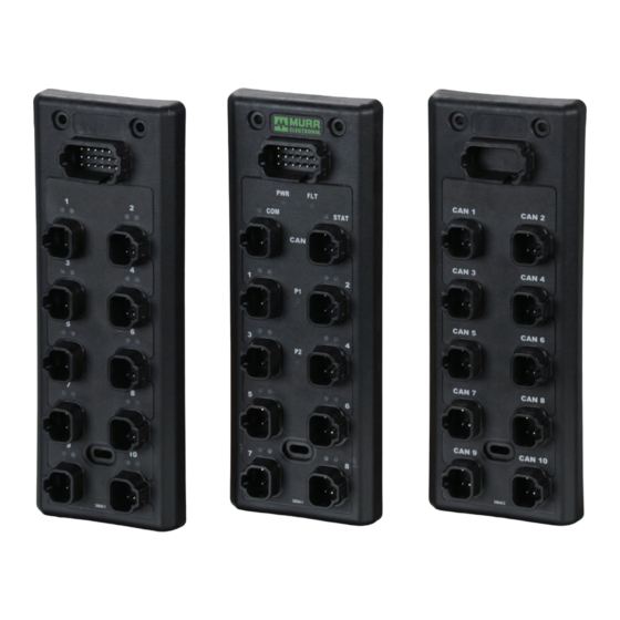
- Page 1 A Murrelektronik Company xtreme DB DP-34044-2 User Guide...
-
Page 2: Table Of Contents
| CONTENTS 1. Concerning this manual 2. Safety Information 2.1 Designated Use 2.2 Target Groups 2.3 Regulations 2.3.1 General Information 2.4 License Disclaimer 2.5 Example of Symbols 2.5.1 Use of Attention Signs 2.5.2 Use of Danger Signs 3. Installation Information 3.1 XtremeDB Installation 4. -
Page 3: Concerning This Manual
A Murrelektronik Company 1. CONCERNING THIS MANUAL The text, illustrations, diagrams and examples used in this manual exist solely for the purpose of explaning the operation and usage of xtremeDB Input/Output modules. If you have any further questions regarding the installation and set-up of the equipment de- scribed in this manual, please do not hesitate to contact us. We will be glad to assist you. Murrelektronik reserves the right to make technical changes or modifications to this manual without prior notice. 2. SAFETY INFORMATION 2.1 DESIGNATED USE The input/output modules of the XtremeDB series are designated for use only in those areas as described in this manual. Strict adherence to the data specified in this manual must be ensured. The products have been developed, manufactured, tested and documented in compliance with currently valid safety codes. The equipment poses no danger to operating personnel or material if configuration, assembly and operation are performed in compliance with the stated handling and safety regulations. Unqualified intervention in the hardware and software of our equipment, disregard of warning labels found on the equipment or non-observance of the information in this manual can result in injury or serious damage to man and/or material. Any application or usage beyond and above this shall be regarded as non-designated. Warning! Good chemical and oil resistance. When using aggressive mediums, material resistance based on application must be checked. -
Page 4: Example Of Symbols
2.5 EXAMPLE OF SYMBOLS 2.5.1 USE OF ATTENTION SIGNS Notes containing important information are specially marked. These are illustrated as follows: Attention text... 2.5.2 USE OF DANGER SIGNS Danger signs are indicated by text and a corresponding symbol inside of a frame CAUTION! Disregard of safety measures may result in damage to equipment and other serious consequences. - Page 5 A Murrelektronik Company 1.3” ATTENTION! Modules must be mounted a minimum of 3mm from each other.
-
Page 6: Module Overview
4. MODULE OVERVIEW Configuration & Power Plug CAN Ports 1 & 2 Non-Isolated 16 Inputs... -
Page 7: Configuring The Baud Rate
A Murrelektronik Company 4.1 CONFIGURING THE BAUD RATE Configuration of the baud rate is done using pins 1 & 7 of the Power and Configuration plug shown below. Currently there are 2 baud rates supported, 250kb and 500kb. If you are connecting to a 250kb network no jumpers are required. If connecting to a 500kb network, jumper pin 1 to pin 7. Configuration & Power Plug Baud1-A Baud1-B 9 10 11 12 13 14 15 16 17 18 Baud Rate No Jumper = 250kb Baud1-A to Baud1-B = 500kb Please note that all devices on the same J1939 network must have the same baud rate... -
Page 8: Configuring The Node Id
4.2 CONFIGURING THE NODE ID The Node ID is configured by jumpering the matching Config-A to Config-B. The Node ID starts with a base source address of 61408 (0xEFE0) with no jumpers installed. The offset address is configured with the use of binary coded decimal (BCD). A power cycle is required when changing the Node ID. If a duplicate source address is on the network on a power up our module will stay in address arbitration mode and will not function. Config4-A Config3-A Config2-A Config1-A Node ID (0-15 Offset) in BCD Config1-A (pin 2) to Config1-B (pin 8) = 1’s Config2-A (pin 3) to Config2-B (pin 9) = 2’s 9 10 11 12 Config3-A (pin 4) to Config3-B (pin 10) = 4’s Config4-A (pin 5) to Config4-B (pin 11) = 8’s 13 14 15 16 17 18 Config1-B Config2-B Config3-B Config4-B Node ID... -
Page 9: Powering The Module
A Murrelektronik Company 4.3 POWERING THE MODULE The module recieves its power from the CAN ports. The module power is limited to 13 amps and is used to power connected modules down the line. This power is also used for all input ports as well. CAN Ports 1 & 2 Non-Isolated Power (J1939) Pin 2 = CAN High Pin 1 = 8-32V DC Pin 4 = CAN Low Pin 3 = Module & Input Ground (A) The connection between CAN1 & CAN2 for the power feed is not fused (protected from short circuit current). During installation the module power wiring on CAN1 &... -
Page 10: Leds
4.4 LEDs During start up the LEDs will come on for 3-5 seconds to verify that they are working (bulb test). PWR LED - Blue Indicates module power is connected FLT LED - Red Fault Status COM LED - Green Communication Status STAT LED - Green Module Status PORT I/O LED - Yellow Left LED = Input A Right LED = Input B Status 1. Steady On = Input is on 2. Flashing On (Input Port)= Input is pulsing... -
Page 11: Led Status
A Murrelektronik Company 4.4.1 LED STATUS COM LED - Green Communication Status COM Fault Description Bootload Mode Indicates traffic on bus Valid Communication Network Source Address (SA) Arbitration 1 Short CANBUS Hardware Fault 2 Short 1 Long Output Control Message Missing 3 Short DM13 Detected* 4 Short * See J1939-73 diagnostics, another device has requested module to stop broadcasting FLT LED - Red Fault Status Fault Description Bootload Mode 1 Short 1 Short... -
Page 12: Circuit Protection
4.5 CIRCUIT PROTECTION Sensor Power The module shall monitor Port Sensor Power current and shut off the sensor power in a port if the maximum current exceeds 3 amps per port. Both short circuit and overcurrent protection is provided. S1 = Port 1 power, 3 amps. S5 = Port 5 power, 3 amps. S2 = Port 2 power, 3 amps. S6 = Port 6 power, 3 amps. S3 = Port 3 power, 3 amps. S7 = Port 7 power, 3 amps. S4 = Port 4 power, 3 amps. S8 = Port 8 power, 3 amps. Module Power The module power delivered by the CAN ports has short circuit protection. This circuit has a separate ground that is supplied by the CAN port as well, Ground (A) 5. MODULE CONFIGURATION 5.1 CONFIGURATION STEPS Module default configuration: • Factory Default Config returns 1 in Status message 1-Status 1, this should not be on if the module has been configured. • Default operation of the module is on/off digital control. PWM control messages are not needed. • Default configuration does not require a Command 0x52 message to enable operation. Command 0x52 (This message needs to be sent until the message confirmation bit is set true): Value Name Data Type... - Page 13 A Murrelektronik Company • Module configuration message, needed when not using module default configuration. • All Status messages need to be turned on (set to value of 1) to be received by controllers at the intervals customer sets. • Enable 24V DC: Enables the low and over voltage fault limits for 24V DC system, otherwise feeding 24V DC to 12V DC system would cause system over voltage error. This is also used for the output overcurrent and short circuit detection. • FREQ1: There needs to be a value put in this parameter or the outputs won’t work. Frequency Pre-Scale to Hz Setting Setting Setting Setting 1140 • Mode 2: Configure all the inputs at the same time, override Command 0x53 and 0x54. • ID1: This is used to give a number to the node that will be transmitted back in Status Message 1-User ID. Default as 0, please note this User ID is not node ID (node address), please see “Configuring the Node ID” for setting node address. • Save Configuration: Turn on the bits (value of 1) after configuring module, inputs and outputs, otherwise changes will only be saved until power cycle. Command 0x53 & 54 (These messages only need to be sent one time): • Configure individual input modes if they haven’t been configured in Mode 2 in Command 0x52. Command 0x57 (This message needs to be written all the time if a person is controlling the counter. A person needs to keep the counter on and needs to be able to reset the count): • Configure the counters/encoder if using.
- Page 14 Status messages - Status message 1 PGN (EF(Controller Source Address)): • Status 1 – Factory default configuration returns a value of 1, this should not be on if a module has been configured. • Status 2 – Configuration Saved returns a value of 1 if the alternate configuration was on (value of 1) and saved the configuration using “Save Configuration” in Command 52. • Status 3 – Alternate configuration, a new configuration was made to the module but hasn’t been saved. • Status 9-14 – Returns a value of 1 each time a Command message 52-57 is sent, to ensure each configuration has been sent. This is on for a brief moment and then resets. Configuration Sample Flowchart: Configure Module (Command 0 x 52) Configure Inputs (Command 0 x 53 & 54) Configure the Counters/Encoder (if using) (Command 0 x 57) Save Configuration (Command 0 x 52) Check Status Message 1 (Software and Node Status)
-
Page 15: Input Configuration
A Murrelektronik Company 5.2 INPUT CONFIGURATION 5.2.1 POWERING THE INPUTS CAN Ports 1 & 2 Non-Isolated Module and Input Power CAN High CAN Low Module and Input Ground(A) Power (Module and Input, 13A) Pin 1 = 8-32V DC Pin 3 = Ground (A) Please note that module and input power is provided via the CAN port... -
Page 16: Input Layout
5.2.2 INPUT LAYOUT Inputs (Ports 5-8) 8-32V DC Power Input B Input A Ground(A) Power Pin 1 = 8-32V DC Pin 3 = Ground A Configurations Input A 1. Positive 2. Ground 3. Frequency/Counter/Encoder (7A & 8A) Input B 1. Positive 2. Ground 3. 4-20mA 4. 0-5V DC 5. 0-10V DC 6. 0-32V DC 9. Ratiometric Inputs • Port 1, Pin 4: Input 1A • Port 1, Pin 2: Input 1B • Port 2, Pin 4: Input 2A • Port 2, Pin 2: Input 2B • Port 3, Pin 4: Input 3A • Port 3, Pin 2: Input 3B • Port 4, Pin 4: Input 4A • Port 4, Pin 2: Input 4B • Port 5, Pin 4: Input 5A • Port 5, Pin 2: Input 5B... -
Page 17: Configuring Inputs
A Murrelektronik Company 5.2.3 CONFIGURING INPUTS Input Mode There are two ways to configure the inputs. All configuration is done through the same PGN. PGN 61408 is used for multiple messages by use of a different value put into the “Command” byte of the PGN. This value is used as an index or pointer as to where the information goes in the module. 1. All Input Configuration (Only used if you want all the inputs to be configured the same. Only works for digital configuration.) Configuring all of the inputs is done through the “MODE2” byte in PGN 61408. The J1939 message structure, Command Value 61408 (0xEFE0) Node offset of 0 82 (0x52) Source Address Transmit rate (0x?? (CSA*)) 50 ms PDU Format Msg timeout 239 (0xEF) 200 ms PDU Specific Priority 224 (0xE0) Built Message... - Page 18 2. Individual Configuration Individual output configuration is done through the “input mode” nibble in PGN 61408 Command Value 61408 (0xEFE0) Node offset of 0 82 (0x52) Source Address Transmit rate (0x?? (CSA*)) 50 ms PDU Format Msg timeout 239 (0xEF) 200 ms PDU Specific Priority 224 (0xE0) Built Message (0x18EFE0??) Name Data Type Byte Bits Description Command Byte Command for index pointer (which message your sending) INMODE1A 1,2,3,4 Mode 0x0=disabled, 0x1=Digital Positive, 0x2=Digital Ground Mode 0x0=disabled, 0x1=Digital Positive, 0x2=Digital Ground, 0x3= 4-20mA (4000-20000), INMODE1B...
-
Page 19: Frequency
A Murrelektronik Company Command Value 84 (0x54) Name Data Type Byte Bits Description Command Byte Command for index pointer (which message you’re sending) Mode 0x0=disabled, 0x1=Digital Positive, 0x2=Digital Ground, 0x7=Digital Positive INMODE8A 1,2,3,4 Frequency, 0x8= Counter 4 bit Mode 0x0=disabled, 0x1=Digital Positive, 0x2=Digital Ground, 0x3= 4-20ma (4000- INMODE8B 5,6,7,8 20000), 0x4= 0-5V DC (0-5000), 0x5= 0-10V DC (0-10000), 0x6= 0-32V DC(0-32000), 0x9= Ratiometric (0-100.0% of source V DC) - Page 20 | INPUT OPERATION The input operation will be different depending on the configuration chosen for the input and the input pin being configured. Input power for each port needs to be enabled to recevie 9-32V DC on pin1, See Control Message 1. Input A 1. Disabled, MODE = 0 It is recommended to disable any inputs that aren’t being used. Putting a “0” in the mode for an input disables the input. 2. Positive On/Off, MODE = 1 This puts the input into the standard discrete positive operation mode. When a positive voltage is present on the input pin, the low bit will turn on. High Bit Low Bit 3.
- Page 21 A Murrelektronik Company Input B 1. Disabled, MODE = 0 It is recommended to disable any inputs that aren’t being used. Putting a “0” in the mode for an input disables it. 2. Positive On/Off, MODE = 1 High Bit Low Bit This puts the input into the standard discrete positive operation mode. When a positive voltage is present on the input pin, the low bit will turn on. 3. Ground On/Off, MODE = 2 High Bit Low Bit This puts the input into the standard discrete ground operation mode. When a ground is present on the input pin, the low bit will turn on. 4. 4-20mA, MODE = 3 This puts the input into 4-20mA mode with a value of 4,000 - 20,000 = 4000 - 20,000 macro amps. A word is allocated for this input. The 1st byte is...
-
Page 22: Frequency/Counter/Encoder Operation
5.3.4 FRE./COUNTER/ENCODER OPERATION 5.3.4.1 FREUENCY 1. The input must be put into Frequency MODE = 7 (Only valid on input 7A & 8A) This puts the Input into frequency operation mode. When a positive signal is present on the input pin, the frequency will be shown. Command Value 83 (0x53) Name Data Type Byte Bits Description Command Byte Command for index pointer (which message your sending) INMODE1A 1,2,3,4 Mode 0x0=disabled, 0x1=Digital Positive, 0x2=Digital Ground Mode 0x0=disabled, 0x1=Digital Positive, 0x2=Digital Ground, 0x3= 4-20mA (4000-20000), INMODE1B 5,6,7,8 0x4= 0-5V DC (0-5000, 0x5= 0-10V DC (0-10000), 0x6= 0-32V DC(0-32000),... - Page 23 A Murrelektronik Company A Murrelektronik Company Value 84 (0x54) Name Data Type Byte Bits Description Command Byte Command for index pointer (which message your sending) Mode 0x0=disabled, 0x1=Digital Positive, 0x2=Digital Ground, 0x7=Digital Positive Frequency, INMODE8A 4 bit 1,2,3,4 0x8= Counter Mode 0x0=disabled, 0x1=Digital Positive, 0x2=Digital Ground, 0x3= 4-20ma (4000-20000), INMODE8B...
-
Page 24: Counter/Encoder
5.3.4.2 COUNTER/ENCODER 1. The input must be put into Counter MODE = 8 (Only valid on input 7A & 8A) This puts the Input into counter operation mode. When a positive signal is present on the input pin, the count will start to accrue. Command Value 83 (0x53) Name Data Type Byte Bits Description Command Byte Command for index pointer (which message your sending) INMODE1A 1,2,3,4 Mode 0x0=disabled, 0x1=Digital Positive, 0x2=Digital Ground Mode 0x0=disabled, 0x1=Digital Positive, 0x2=Digital Ground, 0x3= 4-20mA (4000-20000), INMODE1B 5,6,7,8 0x4= 0-5V DC (0-5000, 0x5= 0-10V DC (0-10000), 0x6= 0-32V DC(0-32000), 0x9= Ratiometric (0-100.0% of source V DC) INMODE2A 1,2,3,4... - Page 25 A Murrelektronik Company Command Value 84 (0x54) Name Data Type Byte Bits Description Command Byte Command for index pointer (which message you’re sending) Mode 0x0=disabled, 0x1=Digital Positive, 0x2=Digital Ground, INMODE8A 1,2,3,4 0x7=Digital Positive Frequency, 0x8= Counter 4 bit Mode 0x0=disabled, 0x1=Digital Positive, 0x2=Digital Ground, 0x3= 4-20ma (4000- INMODE8B 5,6,7,8 20000), 0x4= 0-5V DC (0-5000), 0x5= 0-10V DC (0-10000), 0x6= 0-32V DC(0-32000), 0x9= Ratiometric (0-100.0% of source V DC)
- Page 26 NOTES 1. Turning off the counter doesn’t reset the accumulative value of the counter, a reset is required to reset the count. 2. If roll-over isn’t selected the counter will only accrue up to the setpoint entered. 3. Designated outputs can be controlled by the counter to work asynchronous to the controller, when setpoint has been reached, the output will shut off if the enable bit is on. Please note the output must be turned on as it will not automatically turn on when the counter is on. 4. Turning the counter OFF will not clear the current count value or set point. 5. A counter reset does not clear the counter set point. 6. A counter reset will clear the current count and does not turn the counter OFF. 7. The Roll-Over signal will not change the Output3A and Output4A Enable function. COUNTER OPERATION EXAMPLES Counter Basic Set Point zero, Reset off, Roll Over off Counter Input Counter Input Counter On Counter On Counter Counter Input Counter Set Point Set Point Counter On Counter Set Point Counter - Using Reset Set Point zero, Roll Over off Counter Input Counter Input...
- Page 27 A Murrelektronik Company Counter - Roll Over and Output Enable Set Point set, Reset off, Roll Over on, Output Enable on Counter Input Counter On Counter Set Point Output Command Output Status ENCODER OPERATION • Input 7A & 8A are used for encoder mode. Channel A of the encoder is connected to Input 7A & Channel B is connected to Input 8A. • When the encoder channels are correctly connected, as shown above, firmware takes care of incrementing or decrementing the count. • The functions that work when using encoder mode are tied to counter 7A, the on/off & reset are the only commands that work at this time. 2. The Count and Counter Set Point are shown in the message below/Encoder...
-
Page 28: Input Status
5.2.4.3 INPUT STATUS J1939 Digital Status Name Data Type Byte Bits Description 65301 (0xFF15) Input1A E0=SA Input1B Input2A Input2B Input3A Input3B Input4A Input4B 2 bit 00 = Off, 01 = On, 10 = Fault Input5A Input5B Input6A Input6B Input7A Input7B Input8A Input8B Not used Byte J1939 Analog Status 1 Name Data Type Byte Bits... - Page 29 A Murrelektronik Company J1939 Analog Status 2 Name Data Type Byte Bits Description 65303 (0xFF17) Analog Input 3A Word Low Byte Not Used on this module, discrete only High Byte Analog Input 3B, (4-20mA = 4,000 - 20,000) (0-5V DC = 0 - 5,000mV) Analog Input 3B Word Low Byte (0-10V DC = 0-10,000mV) (0-32V DC = 0 - 32,000mV) (Ratiometric = 0 - 100.0% of source voltage) High Byte Analog Input 4A...
- Page 30 J1939 Frequency Status 65307 (0xFF1B) Source Address Transmit rate 224 (0xE0) 50 ms PDU Format Msg timeout 255 (0xFF) PDU Specific Priority 27 (0x1B) 24 (0x18) Built Message (0x18FF1BE0) Name Data Type Byte Bits Description Input 7A, Hertz is used when the input is configured as a frequency input, Hertz_Count Input 7A Word Low Byte Count is used when the input is configured as a high speed counter High Byte Input 7A, Duty Cycle is used when the input is configured as a frequency input, Duty Cycle_ SP Input 7A Word Low Byte Set Point is used when the input is configured as a high speed counter High Byte Input 8A, Hertz is used when the input is configured as a frequency input,...
-
Page 31: Status Messages
A Murrelektronik Company 5.3 STATUS MESSAGES 5.3.1 MODULE STATUS Status Message 1 (Software and Node Status) Name Data Type Byte Bits Description (0xEF(CSA)) Software Version Version of the current software Byte Software Revision Revision of the current software Status 1 Factory Default Configuration Status 2 Configuration Saved (module is configured) Status 3 Alternate Configuration Received Status 4 Node Alive... - Page 32 Status Message 2 (Configuration and Input Power) Name Data Type Byte Bits Description 65531 (0xFFFB) Config Pair 1 Baud rate configuration jumper is applied Config Pair 2 Node ID 1's configuration jumper is applied Config Pair 3 Node ID 2's configuration jumper is applied Config Pair 4 Node ID 3's configuration jumper is applied Config Pair 5 Node ID 4's configuration jumper is applied Not used, will see (11b) Input Power Port 1 Status of output for Input Power on Port 1, (00 = off), (01 = on), (10 = fault) Not used, will see (11b) Input Power Port 2 Status of output for Input Power on Port 2, (00 = off), (01 = on), (10 = fault) Not used, will see (11b) Input Power Port 3 Status of output for Input Power on Port 3, (00 = off), (01 = on), (10 = fault) Not used, will see (11b) 2 Bit...
-
Page 33: Data Sheet
A Murrelektronik Company 5.4 DATA SHEET 5.4.1 PORT CONFIGURATION Configuration & Power Plug See page 30 for pinout guide 9 10 11 12 13 14 15 16 17 18 CAN Ports 1 & 2 Non-Isolated Power (J1939) (Module & Input-13A) Pin 2 = CAN High Pin 1 = 8-32V DC... - Page 34 Configuration & Power Plug Pinouts 1. Baud1-A 7. Baud1-B 13. N/C 2. Config 1-A 8. Config 1-B 14. N/C 3. Config 2-A 9. Config 2-B 15. N/C 9 10 11 12 4. Config 3-A 10. Config 3-B 16. N/C 13 14 15 16 17 18 5. Config 4-A 11. Config 4-B 17. N/C 6. N/C 12. N/C 18. N/C Baud Rate No Jumper = 250kb Baud1-A to Baud1-B = 500kb. Node ID (0-15) Config1-A to Config1-B = 1s Config2-A to Config2-B = 2s Config3-A to Config3-B = 4s...
-
Page 35: Technical Data
A Murrelektronik Company 5.4.2 TECHNICAL DATA Port Deutsch Plugs Needed Art. No. / Description DP-34044-1 / Combo Block Power Port Connector DT16-18SA-K004 Dimension 3.802" x 10.427" Installation (3) M5 x 1 screws CAN & I/O Port Connector DT06-4S Wedgelock DT Series Communication 2 non-isolated J1939 ports (250kb & 500kb) 4-pin Socket Voltage Range... -
Page 36: Message Structure
6. MESSAGE STRUCTURE All addresses are shown as module configured with no jumpers (Offset = 0) Value 61408 (0xEFE0) Node offset of 0 82 (0x52) Source Address Transmit rate (0x?? (CSA*)) 50 ms PDU Format Msg timeout 239 (0xEF) 200 ms PDU Specific Priority 224 (0xE0) Built Message (0x18EFE0??) *CSA = Controller Source Address... - Page 37 A Murrelektronik Company J1939 Output Control - Control Message 1 (Output Control) Command Value 81 (0x51) Name Data Type Byte Bits Description Command Byte Command for index pointer (which message your sending) Output1A Output1B Output2A Output2B Output3A Output3B Output4A Output4B Not used on this module Output5A Output5B Output6A Output6B 2 bit Output7A Output7B Output8A Output8B Input Power Port1...
- Page 38 J1939 Output Configuration 2 Command Value 83 (0x53) Name Data Type Byte Bits Description Command Byte Command for index pointer (which message you’re sending) INMODE1A 1,2,3,4 Mode 0x0=disabled, 0x1=Digital Positive, 0x2=Digital Ground Mode 0x0=disabled, 0x1=Digital Positive, 0x2=Digital Ground, 0x3= 4-20mA (4000-20000), INMODE1B 5,6,7,8 0x4= 0-5V DC (0-5000, 0x5= 0-10V DC (0-10000), 0x6= 0-32V DC(0-32000), 0x9= Ratiometric (0-100.0% of source V DC) INMODE2A 1,2,3,4...
- Page 39 A Murrelektronik Company J1939 Counter Configuration Message Command Value 61408 (0xEFE0) Node offset of 0 87 (0x57) Source Address Transmit rate 224 (0xE0) 50 ms PDU Format Msg timeout 239 (0xEF) PDU Specific Priority 224 (0xE0) 24 (0x18) Built Message 0x18EFE0E0) Name Data Type Byte Bits Description Command Byte Command for index pointer (which message your sending) Counter 7A On/Off Enable Counter 7A, 00 = Off, 01 = On Used in Encoder mode Counter 7A Reset...
- Page 40 J1939 Digital Status 65301 (0xFF15) EO=SA Node offset of 0 Transmit rate Source Address 224 (0xE0) 50 ms Msg timeout PDU Format 255 (0xFF) 200 ms PDU Specific Priority 21 (0x15) Built Message (0x18FF15E0) Name Data Type Byte Bits Description Input1A Input1B Input2A Input2B Input3A Input3B Input4A Input4B 2 bit 00 = Off, 01 = On, 10 = Fault Input5A Input5B Input6A...
- Page 41 A Murrelektronik Company J1939 Analog Status 1 65302 (0xFF16) Transmit rate Source Address 224 (0xE0) 50 ms PDU Format Msg timeout 255 (0xFF) 200 ms PDU Specific Priority 22 (0x16) Built Message (0x18FF16E0) Name Data Type Byte Bits Description Analog Input 1A Word Low Byte Not Used on this module, discrete only...
- Page 42 J1939 Analog Status 3 65304 (0xFF18) Transmit rate Source Address 224 (0xE0) 50 ms Msg timeout PDU Format 255 (0xFF) 200 ms PDU Specific Priority 24 (0x18) Built Message (0x18FF18E0) Name Data Type Byte Bits Description Analog Input 5A Word Low Byte Not Used on this module, discrete only High Byte Analog Input 5B, (4-20ma = 4,000 - 20,000) (0-5V DC = 0 - 5,000mv) (0-10V DC = 0-10,000mv) Analog Input 5B...
- Page 43 A Murrelektronik Company J1939 Frequency Status 65307 (0xFF1B) Transmit rate Source Address 224 (0xE0) 50 ms Msg timeout PDU Format 255 (0xFF) 200 ms PDU Specific Priority 27 (0x1B) Built Message (0x18FF1BE0) Name Data Type Byte Bits Description Input 7A, Hertz is used when the input is configured as a frequency input, Hertz_Count Input 7A Word Low Byte Count is used when the input is configured as a high speed counter High Byte Input 7A, Duty Cycle is used when the input is configured as a frequency input,...
- Page 44 STATUS MESSAGES Status Message 1 (Software and Node Status) (0xEF(CSA)) Source Address Transmit rate 50 ms 224 (0xE0) PDU Format Msg timeout 239 (0xEF) 200 ms Priority PDU Specific (0x?(CSA)) Built Message (0x18EF??E0) Name Data Type Byte Bits Description Software Version Version of the current software Byte Software Revision Revision of the current software Status 1 Factory Default Configuration Status 2 Configuration Saved (module is configured) Status 3 Alternate Configuration Received...
- Page 45 A Murrelektronik Company Status Message 2 (Configuration and Input Power) 65531 (0xFFFB) Transmit rate Source Address 50 ms 224 (0xE0) Msg timeout PDU Format 255 (0xFF) 200 ms Priority PDU Specific 251 (0xFB) Built Message (0x18FFFBE0) Name Data Type Byte Bits Description Config Pair 1 Baud rate configuration jumper is applied Config Pair 2 Node ID 1's configuration jumper is applied Config Pair 3 Node ID 2's configuration jumper is applied Config Pair 4 Node ID 3's configuration jumper is applied...
- Page 46 Status Message 3 (Controller Information) Status Message 3 (Controller Information) 65532 (0xFFFC) Name Data Type Byte Bits Description Source Address Transmit rate CNFG1 Hardware Configuration Byte 224 (0xE0) 50 ms CNFG2 PCB Assembly Revision PDU Format Msg timeout VBAT 10 Bit Battery Voltage 255 (0xFF) 200 ms 1, 2 PDU Specific Priority TEMP 12 Bit Module Temperature...
-
Page 47: Pgns Used
A Murrelektronik Company 7. PGNs USED Depending on the Node ID selected for the module, the PGNs and source address will be different for the module. The section below shows which are used for each Node ID. Module Control Module Status Digital Input Status Analog Inputs 1A-2B Analog Inputs 3A-4B Analog Inputs 5A-6B EFE0 (EF(CSA)) (SA=E0) FF15 (SA=E0) FF16 (SA=E0) FF17 (SA=E0) FF18 (SA=E0) EFE1 (EF(CSA)) (SA=E1) FF15 (SA=E1) FF16 (SA=E1) FF17 (SA=E1) FF18 (SA=E1) EFE2 (EF(CSA)) (SA=E2) FF15 (SA=E2) FF16 (SA=E2) -
Page 48: Firmware Updates
8. FIRMWARE UPDATES All modules are capable of in the field firmware updates with the use of the xtreme DB Programming Kit (DP-34005-12). DP Loader is the software used to download the firmware to the xtreme DB blocks. Please reference the DP Loader User Manual for instructions. - Page 49 A Murrelektronik Company A Murrelektronik Company 1327 Northbrook Parkway, Suite 460 | Suwanee, GA 30024 P: 770-497-9292 | F: 770-497-9391 | murrinc.com...
Need help?
Do you have a question about the Data Panel xtreme DB DP-34044-2 and is the answer not in the manual?
Questions and answers