Table of Contents
Advertisement
Advertisement
Table of Contents

Subscribe to Our Youtube Channel
Related Manuals for Asus Z590 WIFI


Summary of Contents for Asus Z590 WIFI
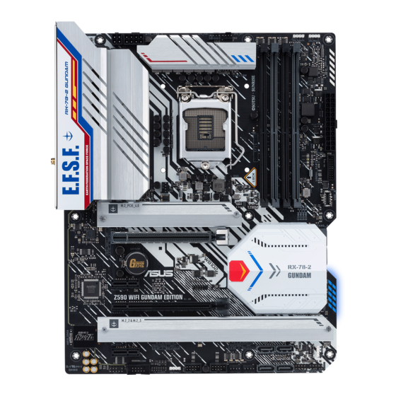
- Page 1 Z590 WIFI GUNDAM EDITION...
- Page 2 Product warranty or service will not be extended if: (1) the product is repaired, modified or altered, unless such repair, modification of alteration is authorized in writing by ASUS; or (2) the serial number of the product is defaced or missing.
-
Page 3: Table Of Contents
Contents Safety information ...................... iv About this guide ......................v Z590 WIFI GUNDAM EDITION specifications summary .......... vi Connectors with shared bandwidth ................x Package contents ....................... xi Installation tools and components ................xii Chapter 1: Product Introduction Before you proceed ................... 1-1 Motherboard layout .................. -
Page 4: Safety Information
Safety information Electrical safety • To prevent electrical shock hazard, disconnect the power cable from the electrical outlet before relocating the system. • When adding or removing devices to or from the system, ensure that the power cables for the devices are unplugged before the signal cables are connected. If possible, disconnect all power cables from the existing system before you add a device. -
Page 5: About This Guide
Refer to the following sources for additional information and for product and software updates. ASUS website The ASUS website (www.asus.com) provides updated information on ASUS hardware and software products. Optional documentation Your product package may include optional documentation, such as warranty flyers, that may have been added by your dealer. -
Page 6: Z590 Wifi Gundam Edition Specifications Summary
DDR4 2666MHz. * 11 Gen Intel ® processors support 3200/2933/2800/2666/2400/2133 natively. * Refer to www.asus.com for the Memory QVL (Qualified Vendors Lists), and memory frequency support depends on the CPU types. 1 x DisplayPort 1.4** 1 x HDMI 2.0*** Graphics specifications may vary between CPU types. - Page 7 Z590 WIFI GUNDAM EDITION specifications summary Raid function for PCIe mode SSD in Intel ® Rapid Storage Technology is available with either 1. Intel ® SSDs installed in both CPU-attached and PCH-attached slots, or 2. any other 3rd party SSDs installed in PCH-attached slots.
- Page 8 Z590 WIFI GUNDAM EDITION specifications summary Fan and cooling related 1 x 4-pin CPU Fan header 1 x 4-pin CPU OPT Fan header 1 x 4-pin AIO Pump header 3 x 4-pin Chassis Fan headers Power related 1 x 24-pin Main Power connector...
- Page 9 12 inch x 9.6 inch (30.5 cm x 24.4 cm) • Specifications are subject to change without notice. Please refer to the ASUS website for the latest specifications. • MyASUS offers a variety of support features such as helping to troubleshoot issues, optimizing product performance, integrating ASUS software, and recovery drive creation.
-
Page 10: Connectors With Shared Bandwidth
Connectors with shared bandwidth RGB_HEADER2 CPU_FAN CPU_OPT ADD_GEN 2_2 KBMS ATX_12V_2 ATX_12V_1 _USB1112 DIGI+ 1442K HDMI U32G2X2_1 U32G1_78 LGA1200 LAN_U32G2_34 BOOT CNVI(WIFI) DRAM AUDIO AIO_PUMP 2242 2260 2280 22110 CHA_FAN1 PCIEX16_1 Intel ® I225-V BATTERY Intel ® Z590 64Mb 128Mb BIOS BIOS PCIEX1_1... -
Page 11: Package Contents
Package contents Check your motherboard package for the following items. Motherboard 1 x Z590 WIFI GUNDAM EDITION motherboard Cables 2 x SATA 6Gb/s cables 1 x ASUS Wi-Fi moving antennas 2 x M.2 Rubber Packages Miscellaneous 1 x M.2 SSD screw package... -
Page 12: Installation Tools And Components
Installation tools and components Phillips (cross) screwdriver PC chassis Power supply unit Intel ® LGA 1200 CPU Intel ® LGA 1200 compatible CPU Fan DDR4 DIMM SATA hard disk drive SATA optical disc drive (optional) Graphics card (optional) M.2 SSD module (optional) 1 Bag of screws The tools and components in the table above are not included in the motherboard package. -
Page 13: Chapter 1: Product Introduction
Before you install or remove any component, ensure that the ATX power supply is switched off or the power cord is detached from the power supply. Failure to do so may cause severe damage to the motherboard, peripherals, or components. Z590 WIFI GUNDAM EDITION... -
Page 14: Motherboard Layout
Motherboard layout 24.4cm(9.6in) RGB_HEADER2 CPU_FAN CPU_OPT ADD_GEN 2_2 KBMS _USB1112 ATX_12V_2 ATX_12V_1 DIGI+ 1442K HDMI U32G2X2_1 U32G1_78 LGA1200 LAN_U32G2_34 BOOT CNVI(WIFI) DRAM AUDIO AIO_PUMP 2242 2260 2280 22110 CHA_FAN1 PCIEX16_1 Intel ® I225-V BATTERY Intel ® Z590 64Mb 128Mb BIOS BIOS PCIEX1_1 Super... - Page 15 11. AURA Addressable Gen2 headers 1-16 12. AURA RGB headers 1-17 13. Clear CMOS header 1-18 14. COM Port header 1-19 15. Front Panel Audio header 1-19 16. System Panel header 1-20 17. Thunderbolt header 1-21 18. Q-LEDs 1-21 Z590 WIFI GUNDAM EDITION...
- Page 16 Contact your retailer immediately if the PnP cap is missing, or if you see any damage to the PnP cap/socket contacts/motherboard components. ASUS will shoulder the cost of repair only if the damage is shipment/ transit-related.
- Page 17 A DDR4 memory module is notched differently from a DDR, DDR2, or DDR3 module. DO NOT install a DDR, DDR2, or DDR3 memory module to the DDR4 slot. Recommended memory configurations DIMM_A1 DIMM_A2* DIMM_A2* DIMM_A2* DIMM_B1 DIMM_B2* DIMM_B2* Z590 WIFI GUNDAM EDITION...
- Page 18 (D/C) from the same vendor. Check with the vendor to get the correct memory modules. • Refer to www.asus.com for the Memory QVL (Qualified Vendors Lists), and memory frequency support depends on the CPU types. Chapter 1: Product Introduction...
- Page 19 Expansion slots Unplug the power cord before adding or removing expansion cards. Failure to do so may cause you physical injury and damage motherboard components. PCIEX16_1 PCIEX1_1 PCIEX16_2 PCIEX1_2 Z590 WIFI GUNDAM EDITION...
- Page 20 Recommended VGA configuration Slot Description Single VGA Dual VGA PCIe 4.0 x16_1 PCIe 3.0 x16_2 Connect a chassis fan to the chassis fan connectors when using multiple graphics cards for better thermal environment. PCIe bifurcation & M.2 settings in PCIe x16 slots (from CPU) PCIe bifurcation &...
- Page 21 • Ensure the cable is fully inserted into the header. Header Max. Current Max. Power Default Speed Shared Control CPU_FAN Q-Fan Controlled CPU_OPT Q-Fan Controlled CHA_FAN1 Q-Fan Controlled CHA_FAN2 Q-Fan Controlled CHA_FAN3 Q-Fan Controlled AIO_PUMP Full-Speed Z590 WIFI GUNDAM EDITION...
- Page 22 Power connectors These Power connectors allow you to connect your motherboard to a power supply. The power supply plugs are designed to fit in only one orientation. Find the proper orientation and push down firmly until the power supply plugs are fully inserted. ATX_12V_1 ATX_12V_2 PIN 1...
- Page 23 2. any other 3rd party SSDs installed in PCH-attached slots. • To enable Intel ® Optane™ Memory (Hybrid Storage device), it must be installed in PCH-attached slots with Intel ® Rapid Storage Technology. The M.2 SSD module is purchased separately. Z590 WIFI GUNDAM EDITION 1-11...
- Page 24 When a device is installed on the M.2_3 socket, SATA6G_56 ports cannot be used. Before creating a RAID set, refer to the RAID Configuration Guide. You can • download the RAID Configuration Guide from the ASUS website. 1-12 Chapter 1: Product Introduction...
- Page 25 The USB 3.2 Gen 1 connector provides data transfer speeds of up to 5 Gb/s. U32_5 VBUS SBU2 TX2+ SBU1 TX2- VBUS RX2+ RX1- RX2- RX1+ TX1- TX1+ VBUS The USB 3.2 Gen 1 module is purchased separately. Z590 WIFI GUNDAM EDITION 1-13...
- Page 26 USB 3.2 Gen 1 header The USB 3.2 Gen 1 header allows you to connect a USB 3.2 Gen 1 module for additional USB 3.2 Gen 1 ports. The USB 3.2 Gen 1 header provides data transfer speeds of up to 5 Gb/s. U32G1_910 PIN 1 USB3+5V...
- Page 27 480 Mbps connection speed. USB_E12 PIN 1 USB_E34 PIN 1 DO NOT connect a 1394 cable to the USB connectors. Doing so will damage the motherboard! The USB 2.0 module is purchased separately. Z590 WIFI GUNDAM EDITION 1-15...
- Page 28 AURA Addressable Gen2 headers The Addressable Gen2 headers allow you to connect individually addressable RGB WS2812B LED strips or WS2812B based LED strips. ADD_GEN 2_2 ADD_GEN 2_1 PIN 1 The Addressable Gen2 headers support WS2812B addressable RGB LED strips (5V/ Data/Ground), with a maximum power rating of 3A (5V), and the addressable headers on this board can handle a combined maximum of 500 LEDs.
- Page 29 RGB LED strip is connected in the correct orientation, and the 12V connector is aligned with the 12V header on the motherboard. • The LED strip will only light up when the system is powered on. • The LED strip is purchased separately. Z590 WIFI GUNDAM EDITION 1-17...
- Page 30 Clear CMOS header This header allows you to clear the Real Time Clock (RTC) RAM in CMOS. You can clear the CMOS memory of date, time, and system setup parameters by erasing the CMOS RTC RAM data. The onboard button cell battery powers the RAM data in CMOS, which include system setup information such as system passwords.
- Page 31 HD Audio. Connect one end of the front panel audio I/O module cable to this header. We recommend that you connect a high-definition front panel audio module to this connector to avail of the motherboard’s high-definition audio capability. Z590 WIFI GUNDAM EDITION 1-19...
- Page 32 System Panel header The System Panel header supports several chassis-mounted functions. PLED PWRSW SPEAKER CHASSIS PANEL PIN 1 HDD_LED RESET PLED • System Power LED header (PLED) The 2-pin header allows you to connect the System Power LED. The System Power LED lights up when the system is connected to a power source, or when you turn on the system power, and blinks when the system is in sleep mode.
- Page 33 BOOT (YELLOW GREEN) VGA (WHITE) DRAM (YELLOW) CPU (RED) The Q-LEDs provide the most probable cause of an error code as a starting point for troubleshooting. The actual cause may vary from case to case. Z590 WIFI GUNDAM EDITION 1-21...
- Page 34 1-22 Chapter 1: Product Introduction...
-
Page 35: Building Your Pc System
NOT install a CPU designed for LGA1155, LGA1156, and LGA1151 sockets on the LGA1200 socket. • ASUS will not cover damages resulting from incorrect CPU installation/removal, incorrect CPU orientation/placement, or other damages resulting from negligence by the user. Z590 WIFI GUNDAM EDITION... - Page 36 Chapter 2: Basic Installation...
-
Page 37: Cooling System Installation
2.1.2 Cooling system installation Apply Thermal Interface Material to the CPU cooling system and CPU before you install the cooling system, if necessary. To install a CPU heatsink and fan assembly Z590 WIFI GUNDAM EDITION... - Page 38 To install an AIO cooler If you wish to install an AIO cooler, we recommend installing the AIO cooler after installing the motherboard into the chassis. AIO_PUMP CPU_FAN CPU_OPT Chapter 2: Basic Installation...
-
Page 39: Dimm Installation
2.1.3 DIMM installation To remove a DIMM Z590 WIFI GUNDAM EDITION... -
Page 40: Installation
2.1.4 M.2 installation Supported M.2 type varies per motherboard. • The illustrations only show the installation steps for a single M.2 slot, the steps are the same for the other M.2 slots if you wish to install an M.2 to another M.2 slot. •... - Page 41 Rotate and adjust the M.2 Q-latch so that the handle points away from the M.2 slot. Install your M.2 to the M.2 slot. Rotate the M.2 Q-Latch clockwise to secure the M.2 in place. Z590 WIFI GUNDAM EDITION...
- Page 42 • To install an M.2 using the removable M.2 Q-Latch screw For M.2_1: Type 2242, 2260, 2280 M.2 (optional) Remove the M.2 rubber pad. Follow this step only if you wish to install an M.2 to type 2242. (optional) If required, remove the pre-installed removable M.2 Q-Latch screw at the 2280 length screw hole.
- Page 43 Install the bundled removable screw stand to the M.2 length screw hole you wish to install your M.2 to. Install your M.2 to the M.2 slot. Secure your M.2 using the bundled removable screw stand’s screw. Removable screw stand Removable screw stand’s screw Z590 WIFI GUNDAM EDITION...
- Page 44 Remove the plastic film from the thermal pads on the bottom of the heatsink. Replace the heatsink. Secure the heatsink using the screws removed previously. 2-10 Chapter 2: Basic Installation...
-
Page 45: Motherboard Installation
Place the motherboard into the chassis, ensuring that its rear I/O ports are aligned to the chassis’ rear I/O panel. Place nine (9) screws into the holes indicated by circles to secure the motherboard to the chassis. DO NOT over tighten the screws! Doing so can damage the motherboard. Z590 WIFI GUNDAM EDITION 2-11... -
Page 46: Atx Power Connection
2.1.6 ATX power connection • DO NOT connect the 4-pin power plug only, the motherboard may overheat under heavy usage. • Ensure to connect the 8-pin power plug, or connect both the 8-pin and 4-pin power plugs. 2-12 Chapter 2: Basic Installation... -
Page 47: Sata Device Connection
2.1.7 SATA device connection Z590 WIFI GUNDAM EDITION 2-13... -
Page 48: Front I/O Connectors
2.1.8 Front I/O connectors To install the front panel header To install USB 3.2 Gen 1 connector ® (USB Type-C USB 3.2 Gen 1 (USB Type-C ® This connector will only fit in one orientation. Push the connector until it clicks into place. To install USB 3.2 Gen 1 connector To install USB 2.0 connector USB 3.2 Gen 1... -
Page 49: Expansion Card Installation
2.1.9 Expansion card installation To install PCIe x16 cards To install PCIe x1 cards Z590 WIFI GUNDAM EDITION 2-15... - Page 50 To install Thunderbolt series card 6-pin PCIe power connector USB Type-C ® port connects to Thunderbolt devices MiniDP in port connects to DP out port on the motherboard or a VGA card USB 2.0 header Thunderbolt header Ensure to install the Thunderbolt series card to a PCIe slot from PCH.
-
Page 51: Wi-Fi Antennas Installation
2.1.10 Wi-Fi antennas installation Installing the ASUS Wi-Fi antennas Connect the bundled ASUS Wi-Fi antennas connectors to the Wi-Fi ports at the back of the chassis. • Ensure that the ASUS Wi-Fi antennas are securely installed to the Wi-Fi ports. -
Page 52: Motherboard Rear And Audio Connections
Motherboard rear and audio connections 2.2.1 Rear I/O connection Rear panel connectors PS/2 mouse/keyboard combo port DisplayPort USB 3.2 Gen 1 Type-A ports Ethernet (RJ-45) port* USB 2.0 Type-A ports HDMI™ port ® USB 3.2 Gen 2x2 port (USB Type-C USB 3.2 Gen 2 Type-A ports Wi-Fi module Optical S/PDIF OUT port... -
Page 53: Audio I/O Connections
Mic In Mic In Mic In Orange – – Center/Sub woofer Center/Sub woofer Black – Rear Speaker Out Rear Speaker Out Rear Speaker Out 2.2.2 Audio I/O connections Audio I/O ports Connect to Headphone and Mic Z590 WIFI GUNDAM EDITION 2-19... - Page 54 Connect to Stereo Speakers Connect to 2-channel Speakers Connect to 4-channel Speakers 2-20 Chapter 2: Basic Installation...
- Page 55 Connect to 5.1-channel Speakers Connect to 7.1-channel Speakers Z590 WIFI GUNDAM EDITION 2-21...
-
Page 56: Starting Up For The First Time
Starting up for the first time After making all the connections, replace the system case cover. Ensure that all switches are off. Connect the power cord to the power connector at the back of the system chassis. Connect the power cord to a power outlet that is equipped with a surge protector. Turn on the devices in the following order: Monitor External SCSI devices (starting with the last device on the chain) -
Page 57: Chapter 3: Bios And Raid Support
Knowing BIOS The new ASUS UEFI BIOS is a Unified Extensible Interface that complies with UEFI architecture, offering a user-friendly interface that goes beyond the traditional keyboard- only BIOS controls to enable a more flexible and convenient mouse input. You can easily navigate the new UEFI BIOS with the same smoothness as your operating system. -
Page 58: Bios Setup Program
BIOS Setup program Use the BIOS Setup to update the BIOS or configure its parameters. The BIOS screens include navigation keys and brief onscreen help to guide you in using the BIOS Setup program. Entering BIOS at startup To enter BIOS Setup at startup, press <Delete> or <F2> during the Power-On Self Test (POST). -
Page 59: Asus Ez Flash 3
ASUS EZ Flash 3 The ASUS EZ Flash 3 feature allows you to update the BIOS without using an OS-based utility. Ensure to load the BIOS default settings to ensure system compatibility and stability. Select the Load Optimized Defaults item under the Exit menu or press hotkey <F5>. -
Page 60: Asus Crashfree Bios 3
ASUS CrashFree BIOS 3 The ASUS CrashFree BIOS 3 utility is an auto recovery tool that allows you to restore the BIOS file when it fails or gets corrupted during the updating process. You can restore a corrupted BIOS file using a USB flash drive that contains the BIOS file. -
Page 61: Raid Configurations
For more information on configuring your RAID sets, please refer to the RAID Configuration Guide which you can find at https://www.asus.com/support, or by scanning the QR code. RAID definitions RAID 0 (Data striping) optimizes two identical hard disk drives to read and write data in parallel, interleaved stacks. - Page 62 Chapter 3: BIOS and RAID Support...
-
Page 63: Appendix
Appendix Appendix Notices FCC Compliance Information Responsible Party: Asus Computer International Address: 48720 Kato Rd., Fremont, CA 94538, USA Phone / Fax No: (510)739-3777 / (510)608-4555 Identification of the assembled product: INTEL Wi-Fi 6 AX201 Identification of the modular components used in the assembly:... - Page 64 Compliance Statement of Innovation, Science and Economic Development Canada (ISED) This device complies with Innovation, Science and Economic Development Canada licence exempt RSS standard(s). Operation is subject to the following two conditions: (1) this device may not cause interference, and (2) this device must accept any interference, including interference that may cause undesired operation of the device.
- Page 65 Tenez cet appareil à distance du ventre des femmes enceintes et du bas-ventre des adolescents. Z590 WIFI GUNDAM EDITION...
- Page 66 ASUS products sold in Vietnam, on or after September 23, 2011,meet the requirements of the Vietnam Circular 30/2011/TT-BCT. Các sản phẩm ASUS bán tại Việt Nam, vào ngày 23 tháng 9 năm2011 trở về sau, đều phải đáp ứng các yêu cầu của Thông tư 30/2011/TT-BCT của Việt Nam.
- Page 67 DO NOT throw the mercury-containing button cell battery in municipal waste. This symbol of the crossed out wheeled bin indicates that the battery should not be placed in municipal waste. Regional notice for California WARNING Cancer and Reproductive Harm - www.P65Warnings.ca.gov Z590 WIFI GUNDAM EDITION...
- Page 68 2014/53/EU. Cijeli di: https://www.asus.com/support/ tekst EU izjave o sukladnosti dostupan je na https://www.asus.com/support/ WiFi yang Beroperasi pada 5150-5350 MHz akan terbatas untuk penggunaan WiFi koji radi na opsegu frekvencija 5150-5350 MHz bit će ograničen na...
- Page 69 ASUSTek Computer Inc. tukaj izjavlja, da je ta naprava skladna s temeljnimi Contains zahtevami in drugimi relevantnimii določili Direktive 2014/53/EU. Polno besedilo izjave EU o skladnosti je na voljo na https://www.asus.com/ support/ WiFi, ki deluje v pasovnem območju 5150–5350 MHz, mora biti v državah, navedenih v spodnjem seznamu, omejen na notranjo uporabo: Declaración de conformidad simplificada para la UE...
-
Page 70: Warranty
ASUS offers a voluntary manufacturer’s Commercial Guarantee. • ASUS zadržava prava na tumačenje odredbi ASUS komercijalnog • ASUS reserves the right to interpret the provisions of the ASUS Commercial Guarantee. jamstva. • This ASUS Commercial Guarantee is provided independently and •... - Page 71 • Si tiene alguna queja o necesidad de un centro de reparación local o el periodo de garantía del producto ASUS, por favor visite el sitio Información de garantía de ASUS de Soporte de ASUS en https://www.asus.com/mx/support/ para •...
-
Page 72: Asus Contact Information
+1-510-739-3777 +1-510-608-4555 Web site https://www.asus.com/us/ Technical Support Support fax +1-812-284-0883 Telephone +1-812-282-2787 Online support https://qr.asus.com/techserv ASUS COMPUTER GmbH (Germany and Austria) Address Harkortstrasse 21-23, 40880 Ratingen, Germany Web site https://www.asus.com/de Online contact https://www.asus.com/support/Product/ContactUs/ Services/questionform/?lang=de-de Technical Support Telephone (DE) +49-2102-5789557 Telephone (AT)
Need help?
Do you have a question about the Z590 WIFI and is the answer not in the manual?
Questions and answers