
Subscribe to Our Youtube Channel
Related Manuals for MICROTRONIX DX-2200

Summary of Contents for MICROTRONIX DX-2200
- Page 1 ICROTRONIX DX-2200 1 SDI V VIEW IDEO WITCHER – V 3.75 ANUAL ERSION 4056 Meadowbrook Drive, Unit 126 London, ON Canada N6L 1E3 www.microtronix.com...
- Page 2 DX-2200 Dual-view 2x2 SDI Switcher User Manual Document Revision History This User Manual provides operating instructions and information on the Microtronix DX-2200 Dual-view 2x1 SDI Video Switcher, (Model PN: DX-2200-SW-02). The following table shows the document revision history. Date Rev. Description Jan.
- Page 3 DX-2200 – Dual-view 2x1 SDI Video Switcher – User Manual Changed zoom to be controlled for selected/non-selected input instead of by input connector number. Added alpha blending effects for secondary layer. Changed second alpha set by TPB / TSB commands to apply to both transition effects and split screen modes.
- Page 4 Mar. 21, 2018 3.75 Updated the Tahoma 18 regular font to correct a character spacing issue NOTE: The graphics overlay feature requires the use of the DX-2200 Software Uploader utility which is used to upload graphic images into the unit. Contact support@microtronix.com...
- Page 5 Safety Critical & Life System Applications – Notice to User The Microtronix DX-2200 SDI Video Products are not designed or approved by Microtronix for use in safety- critical or life-critical system or application in which a failure or malfunction may result in one (or more) of the following outcomes: (a) death or serious injury to people, (b) loss or severe damage to equipment/property, or (c) environmental harm.
-
Page 6: Table Of Contents
DX-2200 – Dual-view 2x1 SDI Video Switcher – User Manual Table of Contents Key Product Features ..........................11 Supported Functionality ........................11 Introduction ............................. 12 Text Overlay OSD Features ......................12 Hardware ..............................13 Power & Operating Requirements ....................13 3.1.1... - Page 7 DX-2200 – Dual-view 2x1 SDI Video Switcher – User Manual Text Fields – Field Type 1 ..................40 4.8.1.10.9.1 Rectangle Fields – Field Type 2 ................41 4.8.1.10.9.2 4.8.1.10.9.3 Rectangle Field Display Example ................42 Corner Marker Fields – Field Type 3 ..............42 4.8.1.10.9.4...
- Page 8 DX-2200 – Dual-view 2x1 SDI Video Switcher – User Manual RS-232 Serial Control Port ......................79 A.2.1 RS-232 3-Pin Header, J2 ......................79 Power Requirements ........................80 A.3.1 Power Connectors ........................80 JTAG Header ........................... 80 A.4.1 JTAG Firmware Upload Procedure ..................80 Reset Pushbutton SW1 ........................
- Page 9 DX-2200 – Dual-view 2x1 SDI Video Switcher – User Manual Listing of Tables Table 1: Description of LED Status Indicators Table 2: Serial Port Command Acknowledgement Codes Table 3: Function of the Inputs for Each Display Mode Table 4: Input Selection SERIAL Command Codes...
- Page 10 DX-2200 – Dual-view 2x1 SDI Video Switcher – User Manual Listing of Figures Figure 1: DX-2200 – Dual-view 2x1 SDI Video Switcher Figure 2: 12Vdc 1.33A 100-240VAC Power Adapter Figure 4: Pin Assignments of 2-pin Power Plug Figure 5: 14.4VDC Lithium Batter and D-TAP Cable Figure 3: Digital Zoom PiP Figure 4: Dual-view –...
-
Page 11: Key Product Features
One DB9, RS-232 Serial Control Port Note: With custom DX-2200 firmware, the RTS & CTS modem signals on the DB9 RS-232 Serial Port can be configured to operate as a second Serial Data Port with RS-232 Receiver and Transmitter signals. A custom serial “Y” cable is used to bring out the two ports. -
Page 12: Introduction
10) Eight font / text size combinations. The text is supplied to the DX-2200 Switcher through the RS-232 serial port. The user can optionally store the text fields in the on-board flash in which case they will be retained power ON/OFF power cycles. -
Page 13: Hardware
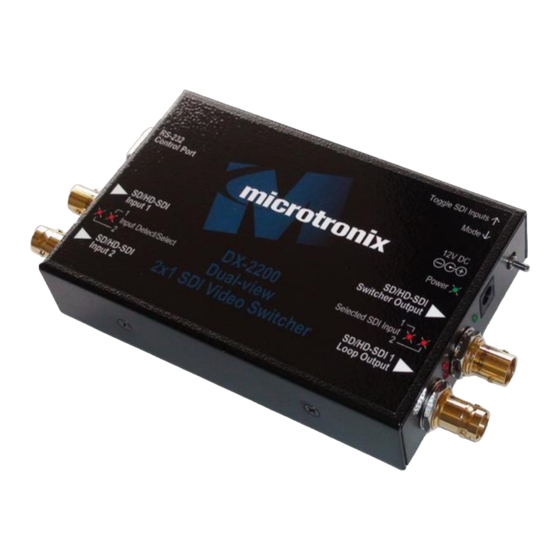
DX-2200 – Dual-view 2x1 SDI Video Switcher – User Manual 3 Hardware The DX-2200 – Dual-view 2x1 SDI Video Switcher is available as a stand-alone product supplied in an enclosure as show in Error! Reference source not found. below or as an open-frame board (for building into embedded video system) as shown in Error! Reference source not found. -
Page 14: Example Of 14.4Vdc Lithium Battery
DX-2200 – Dual-view 2x1 SDI Video Switcher – User Manual Figure 2: 12Vdc 1.33A 100-240VAC Power Adapter Figure 3: Pin Assignments of 2-pin Power Plug 3.1.2 Example of 14.4VDC Lithium Battery A picture of a 14.4VDC the AC power adapter is shown in the figure below. -
Page 15: Environmental Operating Limits
DX-2200 – Dual-view 2x1 SDI Video Switcher – User Manual Figure 4: 14.4VDC Lithium Batter and D-TAP Cable Microtronix does not sell Lithium Ion batteries. The 14.4VDC D-TAP adapter cable (shown in the figure above) can be ordered using Microtronix part number D-TAP-2P-C 3.2 Environmental Operating Limits... -
Page 16: Operation
DX-2200 – Dual-view 2x1 SDI Video Switcher – User Manual 4 Operation 4.1 Display Modes The DX-2200 Switcher supports the display of the SDI video either full-screen or in a variety of dual-viewer window modes. The display modes include: •... -
Page 17: Display Mode 5: Alpha Blended Overlay
The Standby Switcher automatically switches between the two inputs sources. The selected input is the preferred source, but if no signal is available the other source will be displayed. The DX-2200 returns to the preferred source if the signal is restored. - Page 18 DX-2200 – Dual-view 2x1 SDI Video Switcher – User Manual Figure 6: Dual-view – Picture-and-Picture display with text & time code Frame Counter Figure 7: Dual-view – Vertically Stacked with text OSD Figure 8: Alpha Blended PiP with Text Overlay OSD...
-
Page 19: Default Startup Configuration
SDI output will display black. User specific setups can be stored in flash to enable the DX-2200 to start in other modes, for example, with a PiP or PAP configuration or with a preset text overlay. -
Page 20: Output Video Format
ON: SDI 2 input available and selected as primary input 4.5 Output Video Format The settings of the DX-2200 and the video source connected to SDI input 1 (SDI-1) determine the output video format. The output video has three Modes of operation: Output Mode 1: The output video format is the same as the SDI Input 1 format. -
Page 21: Default Output Video Mode
LED. Depending on the operating settings of the DX-2200, the format of the video connected to SDI input 1 may determine the output video format. If the SDI-1 video format is changed the unit may switch to a different output video format. -
Page 22: Serial Mode Of Operation
When SERIAL control is used, the DX-2200 Switcher is controlled via commands sent to the DB9 Serial Control Port. The serial port of the computer connected to the DX-2200 should be configured for 115,200 baud, 1 stop bit, and no flow control. -
Page 23: Input Selection Serial Commands
DX-2200 – Dual-view 2x1 SDI Video Switcher – User Manual 4.8.1.2 Input Selection SERIAL Commands The Input Selection SERIAL Commands, (see Table 1 Table 4), are used to select the SDI input. Switching between SDI inputs is supported at all video resolutions. The table below shows the function of the selected input and the non-selected input for each Display Mode. -
Page 24: Input Auto Switch Serial Command
‘TP’ affect the non-selected layer. The DX-2200 provides Wipe effects in 4 directions and a fade effect. The rate of change for the Wipe effect is programmable in units of pixels per frame with the ‘TPI’ or ‘TSI’ command. The rate of change for the fade is programmable in units of alpha per frame by using the ‘TPA’... - Page 25 The valid range for alpha is 0 to 255.Setting a value greater than 255 causes the DX-2200 to use the default alpha, which is the inverse of the initial alpha. Selected Layer: Complete any transition effect immediately or exit from the Alpha Split modes.
-
Page 26: Example 1A
‘nnnn’ is a number of between one and four digits in length. TSBnnnn The valid range for alpha is 0 to 255.Setting a value greater than 255 causes the DX-2200 to use the default alpha, which is the inverse of the initial alpha. -
Page 27: Example 1B
4.8.1.6 Alpha Blended Overlay Size and Position SERIAL Commands When operating in Alpha Blended Mode, the DX-2200 allows the size and position of the output video windows corresponding to the selected and non-selected inputs to be changed. By default, both windows occupy the full screen. - Page 28 If both the width and height are set to ‘9999’, then the video will be full screen. The minimum size (width or height) for a window is 32 pixels. The DX-2200 will accept a smaller value in the commands, but will never display less than 32x32 pixels.
-
Page 29: Example 1A
DX-2200 – Dual-view 2x1 SDI Video Switcher – User Manual 4.8.1.6.1 E XAMPLE Select the Alpha Blended Overlay Mode and scale both inputs to 1000 x 562 pixels and position them in the center of the output video. This example is designed for use when the switcher operates with 720p output video. -
Page 30: Picture-In-Picture Position & Size Serial Commands
DX-2200 – Dual-view 2x1 SDI Video Switcher – User Manual Figure 14: Alpha Blended Vertical split with frame counter – Example 1b 4.8.1.7 Picture-in-Picture Position & Size SERIAL Commands The position and size of the Picture-in-Picture (PiP) display is selected through character commands sent via the RS-232 port per Table 9 below. -
Page 31: Alpha Blending Transparency Serial Command
(the PiP window). For Alpha Blended Overlay mode, the commands set the transparency of the selected and non-selected inputs. Alpha blending for PiP is stored separately by the DX-2200 so that PiP and Full Screen Alpha Blended Overlay modes can be configured independently. The ‘An’ and ‘Annn’ commands set the PiP transparency when operating in PiP mode, and set the transparency of the non-selected input for Alpha Blended Overlay Mode when executed in any mode other than PiP. - Page 32 DX-2200 – Dual-view 2x1 SDI Video Switcher – User Manual Note: In Alpha Blended Overlay mode with default window positions, setting the transparency of the non-selected input to 0 causes the non-selected layer to completely cover the selected layer, making it invisible.
-
Page 33: Baud Rate Serial Command
255 is 100% transparent 4.8.1.9 Baud Rate SERIAL Command The DX-2200 always powers up at 115200 baud. After power up, the baud rate can be changed using the MBnnnnnnn command, where nnnnnnn is the new baud rate between 9600 and 1000000 baud. -
Page 34: Graphic Overlay Serial Commands
During this time, the active buffer continues to provide the Graphic Overlay video output. After rendering is complete, the DX-2200 switches the active and spare buffers. The buffer that was active before the update becomes the new spare buffer and is cleared by the unit to so that it is ready for text to be rendered again when the next update occurs. -
Page 35: Reset Graphic Field
DX-2200 – Dual-view 2x1 SDI Video Switcher – User Manual Some commands combine the last two operations in the above list, for example the S2S command enables the display of Graphic Field 2 and also updates the layer. The following commands are a simple example that displays a rectangle. These commands are intended for use with the DX-2200 in the factory default configuration: ‘... -
Page 36: Line Color And Transparency
DX-2200 – Dual-view 2x1 SDI Video Switcher – User Manual NOTES: 1) Some monitors will not display the entire video frame, particularly when operating in NTSC or PAL modes. Graphic Fields placed close to the edges of the overlay may not be visible on some monitors. -
Page 37: Background Color And Transparency
DX-2200 – Dual-view 2x1 SDI Video Switcher – User Manual visible and no content on lower video layers will be visible through the Line Color. An alpha of 255 sets the Line Color fully transparent. At this setting the color will be completely invisible. - Page 38 DX-2200 – Dual-view 2x1 SDI Video Switcher – User Manual Table 14: Text and Symbol Fonts Height Fixed Code Range Font Font Name Width Code Pixels (Hexadecimal) Tahoma Bold 20-7E & A0-FF Tahoma Bold 20-7E & A0-FF Tahoma Bold 20-7E & A0-FF Tahoma Bold 20-7E &...
- Page 39 DX-2200 – Dual-view 2x1 SDI Video Switcher – User Manual ✓ Larable Bold 20-7E ✓ Larable Bold 20-7E Wingdings 20-5F Wingdings 20-5F Wingdings 20-5F Notes: Refer to Table 28: Extended ASCII Character Table for a list of characters that are mapped to codes A0-FF.
-
Page 40: Graphic Field Type
The ASCII text is set using the SnnT”Text” command where the characters to be displayed are enclosed in the quotation marks. If a quotation mark is required in the test, it must be preceded by the backslash character. For example to set the text string for Field 7 to display Model "DX-2200" use the command S07T"Model \"DX-2200\"". -
Page 41: Rectangle Fields - Field Type 2
DX-2200 – Dual-view 2x1 SDI Video Switcher – User Manual 4.8.1.10.9.1.1 Text Field Display Example: 4T" DX-2200 " ' set the text to display S4F3 ' select Tahoma Bold 78 pixel height S4R0 ' character red=0 S4G255 ' character green=255... -
Page 42: Rectangle Field Display Example
The x position for coordinate A should be less than that of coordinate B and the y position for coordinate A should be less than the y position for coordinate B. The DX-2200 will automatically reverse the x and/or y coordinates when drawing the corner markers if they are set incorrectly. -
Page 43: Target Marker Fields - Field Type 4
Image Fields – Field Type 5 4.8.1.10.9.6 An Image Field displays an image that has been uploaded to the DX-2200. Image Fields can be used to display a logo or other custom graphics. The DX2200 Uploader software supplied with the product is used to upload images and store them in flash memory. -
Page 44: Rectangle Xywh - Field Type 6
DX-2200 – Dual-view 2x1 SDI Video Switcher – User Manual Images are loaded from flash into main memory the first time they are required for a layer update. The first layer update using an image will be significantly slower than subsequent updates. - Page 45 DX-2200 – Dual-view 2x1 SDI Video Switcher – User Manual Figure 20: Sample of Corner Markers, Target and Text Table 15: Graphic Overlay SERIAL Command Codes Command Code Mode of Operation Graphic Overlay Commands Reset all Graphic Fields to default. This command only resets the parameters of the Fields, but does not update the layer.
- Page 46 DX-2200 – Dual-view 2x1 SDI Video Switcher – User Manual Command Code Mode of Operation Hide (turn off) Graphic Field nn and update the layer to make the change SnnH visible. Disable the visibility setting for a Graphic Field without updating the output.
- Page 47 DX-2200 – Dual-view 2x1 SDI Video Switcher – User Manual Command Code Mode of Operation For Graphic Field nn, set the value of the blue component of the line color to bbb, where bbb is a number between 1 and 3 digits in length and in the range 0 to 255.
- Page 48 DX-2200 – Dual-view 2x1 SDI Video Switcher – User Manual Command Code Mode of Operation Set the Width parameter of Graphic Field nn to the value wwww for both x and SnnWwwww y directions. wwww is a number between 1 and 4 digits in length.
- Page 49 DX-2200 – Dual-view 2x1 SDI Video Switcher – User Manual Command Code Mode of Operation Set the font / size for Field nn. fff is a number of between 1 and 3 digits in length. The following font/size combinations are available.
-
Page 50: Sample Text Field Commands
DX-2200 – Dual-view 2x1 SDI Video Switcher – User Manual Command Code Mode of Operation For Graphic Field nn, set the justification mode. These commands use the field length that is set separately by the SnnJmm command. m = 0... -
Page 51: Example 2
DX-2200 – Dual-view 2x1 SDI Video Switcher – User Manual S1BG255 S1BB255 Figure 21: Example 1 - Red text OSD with white background This text field can be updated and replaced with new text have the same attributes by overwriting with a new text string. -
Page 52: Low Level Text Control Commands
The DX-2200 text overlay process uses two memory buffers where text strings are converted to a rendered image that is mixed with the output video. At any one time, one buffer is being mixed with the video and the other is the spare buffer used to render the next image when the text overlay is changed (eg by the SnV, SnS, or SnH commands). -
Page 53: Application Example 1
4.8.1.13 Frame Counter Overlay SERIAL Commands The DX-2200 has a Frame Counter that displays the frame number as a text overlay on the video. The Frame Counter is supported for progressive video modes only and counts the output frames from the DX-2200. -
Page 54: Frame Counter Modes 2 - 4
The current frame count value used in Modes 2, 3 and 4 can be set by the ‘SFNnnnn’ command. The two count values are independent of each other. Both counters start at zero when the DX-2200 is powered on or reset. The frame counts continue to be updated when the counter is not displayed for progressive video formats. -
Page 55: Sample Frame Counter Commands
Frame Counter Example 1: With DX-2200 starting from the factory defaults, turn on the frame counter in the upper left corner of the screen with white text on a blue background and set the current frame counter value to 11:25:00... -
Page 56: Frame Counter Example 3
DX-2200 – Dual-view 2x1 SDI Video Switcher – User Manual 4.8.1.13.4.3 Frame Counter Example 3: Show the message “Frame Count” in the top left corner of the video and show the frame counter below it. The text properties are set for default white text with no background. - Page 57 DX-2200 – Dual-view 2x1 SDI Video Switcher – User Manual Command Code Mode of Operation Set the Y position - xxxx must be a four-digit number. If the position places the text SFnnYyyyy off screen, then the text is placed at the bottom of the video.
-
Page 58: Overlay Control Serial Commands
The Layer Control commands include a layer number as a parameter that is represented by 'nnn' in the command descriptions. The DX-2200 Dual View Switcher supports a single overlay layer. The layer number used in the commands should be set to '1'. A value of '0' is also accepted and has the same effect. -
Page 59: Low Level Buffer Control
IZING VERLAYS By default, the graphic overlay is the same size as the video output of the DX-2200. The LnKxxxx,yyyy command sets a preferred size for the overlay. If the preferred size is smaller than the video size, the overlay is reduced in size to match the preferred size. The overlay will never be larger than the output video size. - Page 60 DX-2200 – Dual-view 2x1 SDI Video Switcher – User Manual Table 19: Layer Control SERIAL Command Codes Command Mode of Operation Code Layer Control Commands Update layer n by rendering all Fields on the layer(s) to the spare buffer, then switching the spare and active buffers to make the update visible.
-
Page 61: Digital Zoom Command
The selected region is referred to as the zoom window in this manual. The scaler in the DX-2200 will scale up the selected zoom window to the size needed for the output video, resulting in a zoomed in view. - Page 62 ‘ZSLYnnn’ commands. The zoom size is set by the ‘ZSLWnnn’ and ‘ZSLHnnn’ commands. The minimum zoom window the DX-2200 will display is 64 x 64 pixels. If the requested zoom window is larger than the input video size, the window will be reduced to the video size. If the position places the window outside the input video, then the position is automatically adjusted to make the window fit.
- Page 63 Increasing the zoom setting beyond these limits does not increase the magnification. Note: Only certain discrete zoom values are acheivable and the step size between achievable values increases as the zoom increases. The DX-2200 will automatically select the closest acheivable zoom based on the parameter. For example at low zoom a change from 100.0% to 100.1% may produce a change in the display, but at high zoom...
-
Page 64: User Interface Commands
The DX-2200 has 4 DIP switches than can be assigned and a toggle switch that can toggle left and toggle right. Different commands are used to assign the DIP and toggle switches. -
Page 65: Resetting Dx-2200 Switches To Factory Default Configuration
The UF commands are used to assign commands to the user interface functions. For example, the command UF07,00:”M2” assigned user interface function 07, selection number 00 to have the command M2 (set the mode of the DX-2200 to PiP). Any previous command assignment for this user interface function and selection is erased by this command. - Page 66 DIP switch settings are applied only when the DIP switches are changed. This mode may be useful when the DX-2200 is operating primarily under SERIAL control, but the DIP switches are also being used. DIP switch settings are applied when the DIP switches are changed, at startup, and also whenever the mode is changed.
-
Page 67: Dx-2200 Example Configuration Command File
' controls to provide the functions needed in specific user applications. ' This script is one example of how the product can be configured using SERIAL commands. ' ( all lines starting with ' can be transmitted to the DX-2200 and will be ignored as comments ) ' -----------------------------------------------------------------------------------------------... -
Page 68: Output Video Format Command
' Assume the user wants the DX-2200 to display the operating mode using text overlay ' momentarily after each toggle of the switch. This allows us to demonstrate use of text ' command in configuration commands, including the use of \" when a quote is used within ' a string. -
Page 69: Configuration Flash Serial Commands
Note: xxx must always be three digits 4.8.1.23 Configuration Flash Serial Commands The DX-2200 uses Flash memory to retain user configuration information. The Flash is configured using the “Fx” software commands shown in Table 23 below. To save the current configuration, use the 'FW' command. This command saves the current operating settings of the DX-2200 including the display mode (PiP, Stacked, etc…), default resolution, and graphic... -
Page 70: Other Serial Command Codes
DX-2200 – Dual-view 2x1 SDI Video Switcher – User Manual If the DX-2200 firmware is updated, the saved configuration will be lost. Baud rate cannot be saved in the configuration. The DX-2200 always starts at 115200 baud. Table 23: Flash Serial Command Codes... -
Page 71: Manual Mode Of Operation
1 is 1080p video, and input 2 is 1080i, the RI2 command returns return X=0. Even though 1080i is supported by the DX-2200, it cannot be used as a PiP overlay when Input 1 is a progressive video format. In this case, the return value of 0 indicates the video cannot be displayed. -
Page 72: Bypass The Saved Configuration Using The Toggle Switch
To recover from this situation, disconnect power from the unit, push the Toggle Switch left (towards the power connector), and then re-connect power while continuing to hold the Switch for four seconds. The DX-2200 will start with the defaults instead of loading the saved configuration. -
Page 73: Dx-2200 Software Upload Utility
Appendix A or contact Microtronix sales about upgrading the unit. 5.2 Uploading Images The DX-2200 can store one or more images in memory. A stored image can be displayed on the Overlay by configuring a Graphic Field to show that image. -
Page 74: Extended Font Tables
DX-2200 – Dual-view 2x1 SDI Video Switcher – User Manual 6 Extended Font Tables 6.1 Wingding Font The wingdings fonts have been selected from the three wingdings tables and the webding table. Table 27: Windings Character Table Symbol Char Symbol... -
Page 75: Extended Ascii Fonts
DX-2200 – Dual-view 2x1 SDI Video Switcher – User Manual 6.2 Extended ASCII Fonts Table 28: Extended ASCII Character Table Symbol Symbol Symbol Symbol Value Value Value Value 00A0 ¸ 00B8 Ð 00D0 è 00E8 ¡ 00A1 ¹ 00B9 Ñ... -
Page 76: Product Warranty
Customer or a third party (including, but not limited to, loss of data or information, loss of profits, or loss of use). Microtronix reserves the right to revise or update its Products, software, or documentation without obligation to notify any individual or entity. - Page 77 DX-2200 – Dual-view 2x1 SDI Video Switcher – User Manual Page 77 of 93...
-
Page 78: Appendix A: Internal Circuit Board Description
DX-2200 – Dual-view 2x1 SDI Video Switcher – User Manual Appendix A: Internal Circuit Board Description The DX-2200 – Dual-view 2x1 SDI Switcher Board is shown in the following figure. Figure 25: DX-2200 – Dual-view 2x1 SDI Switcher Board The DX-2200 – Dual-view 2x1 SD/HD-SDI Switcher Board utilizes the following hardware devices: •... -
Page 79: Sdi Video Interfaces
An optional splitter cable is available that connects to the DB9 connector and provides both ports on separate DB9 sockets with transmit data on pin 2 and receive data on pin 3. The pin assignments of the DB9 connector on the DX-2200 are provided in the following table. Table 29: RS-232 Serial Port DB9 Pin Assignments... -
Page 80: Power Requirements
The JTAG header is used to program the configuration flash device used load the FPGA device on power up with the DX-2200 program file. This method is designed for OEM’s who have purchased the DX-2200 product as an open-frame board. The procedure required the user to load a JIC file into the on-board serial flash configuration device through the JTAG Interface. -
Page 81: Reset Pushbutton Sw1
DX-2200 – Dual-view 2x1 SDI Video Switcher – User Manual 4) A dialog box may appear with a selection for EP3C120 or EP4CE115. Select EP3C120, and click Close. 5) Select the line in the programmer window containing the EP3C120 device. - Page 82 DX-2200 – Dual-view 2x1 SDI Video Switcher – User Manual Page 82 of 93...
-
Page 83: Appendix B: Usb To Rs-232 Serial Port Adapter
DX-2200 – Dual-view 2x1 SDI Video Switcher – User Manual Appendix B: USB to RS-232 Serial Port Adapter The USB to DB9 RS-232 Serial Port Adapter Kit (PN: 811-USB-RS232 Kit) is used to connect the DB9F Serial Port to a USB port of a PC. The Kit consists of a USB 2.0 to RS232 DB9 Serial Adapter Cable (StarTech PN: ICUSB232V2) and a 6 foot male to female DB9 RS232 serial cable as shown in the figure below. -
Page 84: Establishing Serial Communications
Type the “ENTER” to get an * response from the unit. iv) Type rv to display the version of the software used by the DX-2200 product. This confirms Serial communication with the DX-2200 product. The figures below show some of the PuTTY configuration screens. - Page 85 DX-2200 – Dual-view 2x1 SDI Video Switcher – User Manual Figure 29: PuTTY Session User Settings Figure 30: PuTTY Terminal Settings Page 85 of 93...
- Page 86 DX-2200 – Dual-view 2x1 SDI Video Switcher – User Manual Figure 31: PuTTY Serial Port Settings Page 86 of 93...
- Page 87 DX-2200 – Dual-view 2x1 SDI Video Switcher – User Manual Page 87 of 93...
-
Page 88: Appendix C: Regulatory Compliance Information
4056 Meadowbrook Drive, Unit 126, London, ON Canada TEL: +(1) 519-690-0091 The Responsible Party declares the DX-2200, 2x1 SDI Video Switcher product has been tested and found to comply FCC PART 15, SUBPART B, Class A – Unintentional Radiators. Operation is subject to the following two conditions: (1) This device may not cause harmful interference, and (2) this device must accept any interference received, including interference that may cause undesired operation. -
Page 89: Ce Declaration Of Conformity
STANDARD(S) TO WHICH CONFORMITY IS DECLARED: The DX-2200, 2x1 SDI Video Switcher product has been tested in accordance with: • CISPR 24: 2010 / EN 55024:2010 – Electromagnetic Compatibility Requirements – Information Technology Equipment –...
Need help?
Do you have a question about the DX-2200 and is the answer not in the manual?
Questions and answers