Advertisement
Quick Links
Quick Start Guide
SAFETY CHECKLIST
S
urvey the test station. Make sure it is safe & orderly.
A
lways keep unqualified/unauthorized personnel away from the test area.
F
amiliarize yourself with safety protocols in the event of a problem.
E
xercise caution and never touch products or connections during a test.
T
rain operators. Never touch clips directly and always connect the return lead first.
Y
ou should always know when a test is being performed.
WARNING: THIS GUIDE WAS CREATED FOR OPERATORS HAVING SOME FAMILIARITY WITH ELECTRICAL SAFETY
TESTING. AN ELECTRICAL SAFETY TESTER PRODUCES VOLTAGES AND CURRENTS THAT CAN CAUSE HARMFUL
OR FATAL ELECTRIC SHOCK. TO PREVENT ACCIDENTAL INJURY OR DEATH, THESE SAFETY PROCEDURES MUST
BE STRICTLY OBSERVED WHEN HANDLING AND USING A TEST INSTRUMENT. CONTACT US AT
INFO@ARISAFETY.COM FOR MORE INFO ON HOW TO GET TRAINED ON ELECTRICAL SAFETY TESTING.
SC6540
Model SC6540
TÜV Rheinland
US
C
Advertisement

Related Manuals for Associated Research SC6540-HH


Summary of Contents for Associated Research SC6540-HH
- Page 1 Quick Start Guide SC6540 Model SC6540 TÜV Rheinland SAFETY CHECKLIST urvey the test station. Make sure it is safe & orderly. lways keep unqualified/unauthorized personnel away from the test area. amiliarize yourself with safety protocols in the event of a problem. xercise caution and never touch products or connections during a test.
-
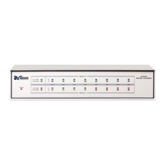
Page 2: Front Panel Controls
FRONT PANEL CONTROLS POWER INDICATOR: Indicates the power has been turned ON. For a SC6540 Main, this lights up when the power switch on the rear panel of the unit is turned ON. For a SC6540 Secondary, this lights up when the power switch on the host instrument is turned ON. -
Page 3: Back Panel Controls
(Secondary Scanner, HGS, Back Panel) SCANNER BUS INPUT: Interconnect port for the control cable between the SC6540 Secondary and an automated Associated Research electrical safety tester or SC6540 Main scanner. SAFETY GROUND CONNECTOR: Must be connected to a known good ground system to ensure operator safety. - Page 4 BACK PANEL CONTROLS (Main Scanner, HGM, Back Panel) BUS INTERFACE: Standard connector for interconnection to the USB/RS-232 Bus interface. Optional IEEE-488 interface or Ethernet Interface may be substituted for the USB/RS-232. FUSE RECEPTACLE: To change the fuse, unplug the power (mains) cord and turn the fuse receptacle counter-clockwise.
- Page 5 Main and a Secondary. A Main Scanner can only be controlled remotely via a PC. A secondary Scanner can be controlled locally by an Associated Research testing instrument or by a Main Scanner. MAIN A Main Scanner communicates directly with a PC via a USB/RS-232 (standard), GPIB interface, or Ethernet.
- Page 6 BACK PANEL CONFIGURATIONS The modular design allows for a variety of configurations. In addition to Main or Secondary configurations, the scanners can also be set-up with the following configurations: 8 or 16 High Voltage testing channels, 8 High Voltage and Ground Bond testing channels, and 8 or 16 Ground Bond testing channels.
- Page 7 CONNECTIONS WARNING: UNDER CERTAIN CONDITIONS HIGH VOLTAGE CAN APPEAR ON THE CABINET OF THE SC6540. THE GROUND TERMINAL ON THE REAR PANEL OF THE SC6540 MUST BE CONNECTED TO A GOOD EARTH GROUND TO ENSURE OPERATOR SAFETY. CAUTION: MULTIPLE HIGH VOLTAGE OR CONTINUITY CURRENT CHANNELS CAN BE SET TO ACTIVATE SIMULTANEOUSLY.
- Page 8 Low (L) for the Return connection, or Open (O) for OFF. Channel setup is done using the HypotULTRA menu or accompanying automation software. For information on SC6540 setup through Associated Research’s Autoware ® Automation Software, consult the Autoware 3 help file.
- Page 9 CONNECTIONS OPERATING THE SC6540 WITH HYPOTULTRA (Continued) OPERATION Once the SC6540 is incorporated into a test system, it will act as an extension of the HypotULTRA. The outputs will only activate while a test is being performed and will deactivate when the test is not running. When a failure is detected, the test will stop, the output will be deactivated and the HypotULTRA will give a visual and audible indication of failure.
- Page 10 12 gauge wire for operation at 30 amps, and 10 gauge wire for 40 amps. The wires should be attached using the hook-style crimp lugs provided, to minimize connection resistance. The Kelvin connection of an Associated Research Ground Bond tester will end at the Ground Bond input terminals of the SC6540 Scanner. For...
- Page 11 CONNECTIONS OPERATING THE SC6540 WITH OMNIA II 8204 (Continued) GROUND BOND CONNECTIONS OMNIA II REMOTE INTERFACE RS232 SCANNER 1 SCANNER 2 SIGNAL OUTPUT SIGNAL INPUT OUTPUT INPUT SENSE+ SENSE - CAT. II H.V. T10A 250V CURRENT RETURN CAUTION HIGH VOLTAGE 5KV MAX.
- Page 12 Low (L) for the Return connection, or Open (O) for OFF. Channel setup is done using the OMNIA II menu or accompanying automation software. For information on the SC6540 setup through Associated Research’s Autoware ® Automation Software, consult the Autoware 3 help file.
- Page 13 CONNECTIONS OPERATING THE SC6540 WITH OMNIA II 8204 (Continued) OPERATION Once the SC6540 is incorporated into a test system, it will act as an extension of the OMNIA II. The outputs will only activate while a test is being performed and will deactivate when the test is not running.
- Page 14 OPERATING THE SC6540 WITH LINECHEK 620L SETUP This option allows the 620L to be connected to an Associated Research SC6540 Modular Scanning Matrix, model HN. With this option installed and a Scanner connected to the Scanner control bus on the rear of the instrument, the 620L and accompanying Scanner can be used for multi-point Line Leakage testing.
- Page 15 CONNECTIONS OPERATING THE SC6540 WITH LINECHEK 620L (Continued) OPERATION Within the Line Leakage Edit screen on the 620L, the “Scanner Select” parameter (soft key) will automatically appear when the highlighted cursor moves to the Scanner Setup area using the Up and Down Arrow keys or Enter key.
- Page 16 Safety Is Our Only Focus ® For additional information about these and other key features of the SC6540, please consult the full Operation and Service Manual or call us toll-free 1-800-858-TEST (8378) or 1-847-367-4077 © Associated Research arisafety.com • FOLLOW US!
Need help?
Do you have a question about the SC6540-HH and is the answer not in the manual?
Questions and answers