Associated Research SC6540 Operation And Service Manual
High voltage and high current scanning matrix
Hide thumbs
Also See for SC6540:
- Quick start manual (16 pages) ,
- Quick start manual (16 pages) ,
- Operation and service manual (69 pages)
Table of Contents
Advertisement
Quick Links
Advertisement
Table of Contents

Related Manuals for Associated Research SC6540


Summary of Contents for Associated Research SC6540
- Page 1 OPERATION AND SERVICE MANUAL MODEL SC6540 High Voltage and High Current Scanning Matrix SERIAL NUMBER Item 38616 Ver 3.13 Associated Research 28105 North Keith Drive - Lake Forest, IL 60045 USA T. 1-847-367-4077 F. 1-847-367-4080 info@arisafety.com www.arisafety.com...
- Page 2 DECLARATION OF CONFORMITY Manufacturer: Associated Research, Inc. Address: 28105 North Keith Dr. Lake Forest, IL 60045 Product Name: SC6540® High Voltage and High Current Scanning Matrix Model Number: SC6540 Conforms to the following Standards: Safety: UL 61010-1:2012 CAN/CSA-C22.2 NO. 61010-1-12...
-
Page 3: Table Of Contents
4.2.2. Connection Diagrams ................. 23 4.2.3. Setup ..................... 25 4.2.4. Operation ....................27 4.3. Operation of the SC6540 with OMNIA 8100/8200 Series ....... 29 4.3.1. Cables and Connections Description ..........29 4.3.2. Connection Diagrams ................. 30 4.3.3. Setup ..................... 33 4.3.4. - Page 4 4.4.2. Connection Diagram ................37 4.4.3. Scanner Addressing ................39 5. BUS REMOTE INTERFACE GPIB / USB / RS-232 / ETHERNET ....44 5.1. USB/RS-232 Interface ................... 44 5.1.1. RS-232 Connector ................44 5.1.2. Communications Port Configuration ..........45 5.1.3. Sending and Receiving Commands ..........45 5.2.
-
Page 5: Introduction
5-Year Program All Associated Research instruments include the opportunity to extend the standard warranty for up to a period of 5 years. Returning instruments to Associated Research for their annual calibration and inspection will extend the instrument's warranty for an additional year. - Page 6 Elimination of any connections in the earth grounding system or bypassing any safety systems will void this warranty. This warranty does not cover accessories not of Associated Research, Inc. manufacture. Parts used must be parts that are recommended by Associated Research, Inc. as an acceptable specified part. Use of non-authorized parts in the repair of this instrument will void the warranty.
-
Page 7: Safety Symbols
1.2. Safety Symbols 1.2.1. Product Marking Symbols Product will be marked with this symbol when it is necessary to refer to the operation and service manual in order to prevent injury or equipment damage. Product will be marked with this symbol when hazardous voltages may be present. - Page 8 Direct Current, DC: Current that flows in one direction only. The source of direct current is said to be polarized and has one terminal that is always at a higher potential than the other. Frequency: The number of cycles an AC waveform repeats over time. Usually given in Hertz (Hz). Ground: Refers to the point of low potential in a circuit to which all other voltages are referenced.
-
Page 9: Safety
LAKE FOREST, IL 60045-4546 U.S.A. FAX: 1 (847) 367-4080 E-MAIL: info@asresearch.com Service Interval Associated Research, Inc. will not be held liable for injuries suffered if the instrument is not properly maintained and safety checked annually. See section 1.1. Warranty Policies for more information. -
Page 10: Test Station
1.4.2. Test Station Location Select an area away from the mainstream of activity where employees do not walk while performing their normal duties. If this is not practical because of production line flow, then the area should be roped off and marked for HIGH VOLTAGE TESTING. No employees other than test operators should be allowed inside. -
Page 11: Test Operator
1.4.3. Test Operator This instrument generates voltages and currents that can cause harmful or fatal electric shock and must only be operated by a skilled worker trained in its use. The operator should understand the electrical fundamentals of voltage, current, and resistance. - Page 12 currents generated by the instrument are very dangerous. If contacted, the instrument may cause heart-related problems. Please have the test operator consult a physician for recommendations.
-
Page 13: Key Features And Benefits: Sc6540
1.5. Key Features of the SC6540 The SC6540 can be purchased as a “main” scanning matrix with its own power source, or as a “secondary” CONFIGURABLE scanning matrix controlled through an automated SCANNING MATRIX Associated Research instrument. Each main Scanner can control up-to four additional secondary Scanners, allowing a total of 80 test points. -
Page 14: Getting Started
If the instrument is damaged, notify the carrier and Associated Research, Inc.’s customer support department. Please save the shipping carton and packing material for the carrier’s inspection. Our customer support department will assist you in the repair or replacement of your instrument. - Page 15 DESCRIPTION AR PART NUMBER 100’ White 18AWG Wire 37534 High Voltage Cable Kit HS-8-13 W/ GROUND BOND MODULE 20 Hook-Style Crimp Lugs 38599 W/ HYPOTULTRA 3 INTERCONNECT High Voltage Cable HS-8-12 2 Return Cables HS-8-11 W/ HYPOTULTRA INTERCONNECT High Voltage Cable HS-8-12 2 Return Cables HS-8-11...
- Page 16 SC6540 Contents of the Carton Additional Carton Contents for use with OMNIA 80xx Additional Carton Contents for use with OMNIA 81xx and OMNIA 8204/8254...
- Page 17 Additional Carton Contents for use with OMNIA 8206, 8256, 8207, 8257 Additional Carton Contents for use with HypotULTRA...
-
Page 18: Installation
This may cause internal damage and represents a safety risk to the operator. The SC6540 must be connected to a good ground. Be certain that the power wiring is properly polarized and that... -
Page 19: Basic Connections
the proper low resistance bonding to ground is in place. 2.2.3. Basic Connections Power Cable The instrument is shipped with a line cord containing a protective earth ground. When the line cord is connected to an appropriate AC power source the cable will connect the chassis to earth ground. - Page 20 Failure to operate this instrument within the specified conditions could result in damage. If the instrument is used in a manner not specified by the manufacturer, the protection provided by the instrument may be impaired. More Information For more information on test operator and workstation safety please visit the Events and Training section of our website at http://www.asresearch.com/events- training/Default.aspx...
-
Page 21: Specifications And Controls
3. SPECIFICATIONS AND CONTROLS 3.1. SC6540 Functional Specifications SC6540 SC6540 MAIN SECONDARY 115 VAC (+/-10%), 50/60 Hz, Single Input Phase 230 VAC (+/-10%), 50/60 Hz Single Phase User Selectable Fuse 250V/2A/Fast-Blow PC Control GPIB, USB/RS232, or Ethernet 1 Scanner Bus Output... -
Page 22: Instrument Controls
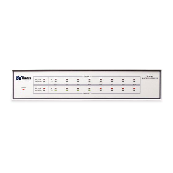
1. POWER INDICATOR: Indicates the power has been turned ON. For a SC6540 Main, this lights when the power switch on the rear panel of the unit is turned ON. For a SC6540 Secondary, this lights when the power switch on the host instrument is turned ON. -
Page 23: Rear Panel Controls
SC6540 in a multiple SC6540 system. 6. ADDRESS SWITCHES: 8-pin DIP switch used to address the modules in a SC6540 secondary or used to configure the address of a SC6540 main. 7. CURRENT INPUT JACK: Connector used to attach the high current input lead or continuity current input lead from the host instrument. - Page 24 10. BUS INTERFACE: Standard 9 pin D-Subminiature connector for the USB/RS-232 Bus interface. Optional IEEE 488 or Ethernet interface available. 11. POWER SWITCH: Switch with international ON ( | ) and OFF (0) markings. 12. FUSE RECEPTACLE: To change the fuse, unplug the power (mains) cord and turn the fuse receptacle counter-clockwise.
-
Page 25: Operating Instructions
4. OPERATING INSTRUCTIONS 4.1. Scanner Configurations The SC6540 is available in 2 configurations according to how it sends and/or receives data: a main and a secondary. A main Scanner can only be controlled remotely via a PC. A secondary Scanner can be controlled locally by an Associated Research, Inc. -
Page 26: Cables And Connections Description
HypotULTRA. 4.2.1. Cables and Connections Description A number of hardware and interconnect cables are included with the SC6540 Scanner depending on its configuration and the number of modules. The following hardware and interconnect cables are included with each of the following items:... -
Page 27: Connection Diagrams
Under certain conditions high voltage can appear on the cabinet of the SC6540. The ground terminal on the rear panel of the SC6540 must be connected to a good earth ground to ensure operator safety. 4.2.2. Connection Diagrams... - Page 28 HypotULTRA and SC6540 Secondary HypotULTRA 3 and SC6540 Main...
-
Page 29: Setup
HypotULTRA 3 and SC6540 Secondary 4.2.3. Setup The SC6540 Scanner channels can be set as High (H) for high voltage or Continuity testing output, Low (L) for the return connection, or Open (O) for OFF. Channel setup is done using the HypotULTRA / HypotULTRA III menu or accompanying automation software. - Page 30 The “Int Scanner” parameter in the menu pertains to an internal 8-channel Scanner and the “Ext Scanner1” parameter pertains to an 8- channel high voltage SC6540 Scanner. NOTE: The HypotULTRA can only control up to one external 8-channel scanner (model HN).
-
Page 31: Operation
8 external). The “Scanner” parameter in the menu pertains to an internal 8- channel Scanner and the “Ex Scanner” parameter pertains to an 8-channel high voltage SC6540 Scanner. NOTE: The HypotULTRA III can only control up to one external 8-channel scanner (model HN). - Page 32 HypotULTRA III is turned on. Main Scanner Power The SC6540 main is powered on by putting the switch on the rear panel of the unit in the ON position. The SC6540 Scanner channels will activate when the TEST signal is sent via a PC.
-
Page 33: Operation Of The Sc6540 With Omnia 8100/8200 Series
II (8200) series. 4.3.1. Cables and Connections Description A number of hardware and interconnect cables are included with the SC6540 Scanner depending on its configuration and the number of modules. The following hardware and interconnect cables are included with each of the following items:... -
Page 34: Connection Diagrams
Ground Bond Connections The rear panel of the SC6540 can include up to sixteen output terminals for Ground Bond testing if this configuration is selected at the time of purchase. We recommend using standard 12 gauge wire for operation at 30 amps and 10 gauge wire for 40 amps. - Page 35 OMNIA 8100 Series and SC6540 Main OMNIA 8100 Series and SC6540 Secondary...
- Page 36 OMNIA 8200 Series and SC6540 Main – ACW, DCW, IR, GND Bond and Continuity OMNIA 8200 Series and SC6540 Secondary - ACW, DCW, IR, GND Bond and Continuity...
-
Page 37: Setup
OMNIA 8200 Series and SC6540 Main – Line Leakage Testing OMNIA 8200 Series and SC6540 Secondary – Line Leakage Testing Line leakage testing only available on 8206, 8256, 8207 and 8257 4.3.3. Setup... - Page 38 The SC6540 Scanner channels can be set as High (H) for high voltage or Continuity testing output, Low (L) for the return connection, or Open (O) for OFF. Channel setup is done using the OMNIA menu or accompanying automation software. For information on SC6540 setup through Associated Research’s Autoware Automation Software, consult the Autoware S8456 manual.
-
Page 39: Operation
O (Open) – Channel is neither an output nor a return. 4.3.4. Operation Once the SC6540 is incorporated into a test system, it will act as an extension of the OMNIA. The outputs will only activate while a test is being performed, and will deactivate when the test is not running. -
Page 40: Interfacing Multiple Sc6540S
Once the SC6540 secondary is connected to OMNIA, the “power on” LED will light as soon as the power switch of the OMNIA is turned on. Main Scanner Power The SC6540 main is powered on by putting the switch on the rear panel of the unit in the ON position. LED Indicators The two leftmost LEDs for Module A and Module B indicate the type of module that has been installed. -
Page 41: Connection Diagram
38599 The high voltage splitter should be connected to the high voltage input terminal on the rear panel of the SC6540 main. This allows for a high voltage input cable from the host instrument and an output terminal for connection of high voltage to the next Scanner. - Page 42 HypotULTRA and SC6540 Scanner Interconnection Example with 1 Main and 2 Secondarys Refer to the connection diagram of the applicable safety tester for the required cabling. Use supplied Hook-Style Crimp Lugs and user specified wire for Scanner- to-Scanner interconnection.
-
Page 43: Scanner Addressing
Remote Interface GPIB/USB/RS232/Ethernet. Addressing Secondary Units Each of the SC6540 secondary units also have an 8 pin DIP address switch which must be configured based upon the type of module installed (HV or High Current) and the total number of points controlled by each main for each function. The first... - Page 44 PIN 5 = 1 PIN 6 = 2 PIN 7 = 4 PIN 8 = 8 Channel Assignment Each Scanner is capable of supporting two 8-channel modules. Each module is physically marked on the front and rear panel with channel numbers 1 through 8. To direct the control signals to the correct channel when using multiple scanners, the address setting function must be used.
- Page 45 If a SC6540 main is configured with either two high current modules or two high voltage modules, module A will be assigned a 0 address for channels 1-8 and module B will be assigned a 1 address for channels 9-16.
- Page 46 Address 6 PIN 2 = ON PIN 3 = ON PIN 4 = OFF Position B PIN 5 = ON Address 7 PIN 6 = ON PIN 7 = ON PIN 8 = OFF Secondary 4 Position A PIN 1 = OFF Address 8 PIN 2 = OFF PIN 3 = OFF...
- Page 47 Example 3: A test system requiring 40 HV and 40 HC points set up in a different configuration. The main Scanner and the first secondary Scanner are set up with high voltage modules in modules A and B. The second secondary Scanner is set up with one high voltage module and one high current module.
-
Page 48: Bus Remote Interface Gpib / Usb / Rs-232 / Ethernet
ETHERNET This section provides information on the proper use and configuration of the bus remote interface. The USB/RS-232 remote interface is standard on the SC6540 but the GPIB (IEEE-488) and interface option can be substituted for the USB/RS- 232 interface. The USB/RS-232 interface uses the same command set as the GPIB interface for setting test parameters;... -
Page 49: Communications Port Configuration
5.2. GPIB Interface This interface is optional on the SC6540 and provides all of the control commands and parameter setting commands of the USB/RS-232 interface along with 488.2 Common Commands and SRQ capability. All commands can be found in section 5.5. - Page 50 Handshake Lines: The transfer of message bytes between devices is done via three asynchronously control lines. Referred to as three-wire interlocked handshake. This guarantees that message bytes on the data lines are sent and received without transmission error. NRFD (not ready for data) indicates when a device is ready or not ready to receive a message byte.
-
Page 51: Gpib Address Setup
A maximum separation of 4 m between any two devices and an average separation of 2 m over the entire bus. A maximum total cable length of 20 m. No more than 15 device loads connected to each bus, with no less than two- thirds powered on. -
Page 52: Ethernet Interface
The Ethernet port is for use with a standard CAT-5 Ethernet cable and may be connected to any compatible PC. The 9-pin D-type subminiature connecter labeled “RS232” is for connection of the SC6540 to an RS-232 communication bus. All of the Ethernet commands (excluding the query commands) will respond... - Page 53 was recognized by the instrument. If there was an error with the command string, the instrument will respond with 15 hex (21 decimal), the Not Acknowledge (NAK) ASCII control code. The presence of this response does not mean that the instrument (in the case of these commands only) completed the command.
- Page 54 Associated Research, Inc. Ethernet Card Communications Information (To be completed by Network Administrator) Ethernet Card Address: ______:______:______:______:______ Device Name: _____________________ Device IP Address: _______._______._______._______ Gateway IP Address: _______._______._______._______ Subnet Mask: _______._______._______.______...
-
Page 55: Autoware Ip Track
5.6. Autoware IP Track The SC6540 scanner does not contain a display to keep track of Ethernet settings. The Autoware IP Track program can be used to track the SC6540 Ethernet settings including IP Address, Subnet Mask and Default Gateway. The Autoware IP Track program can be downloaded from the Associated Research, Inc. - Page 56 If two scanners have the same dip switch configuration, the user will be warned and the program will recommend that the configuration be changed to the next available decimal value: A unit can also be edited by using the SCAN, CHANGE IP and RECOVER USING MAC buttons located at the bottom of the Autoware IP Track screen.
- Page 57 RECOVER USING MAC button, the program will display a window with the following message: “Please Enter the MAC address of the Associated Research Unit you wish you recover. The MAC address is located inside the unit in 00-20-4a-xx-xx-xx format.” The user can type the MAC address of the associated unit into the MAC Address field and hit OK to attempt a recovery of the instrument.
- Page 58 BACK: Pressing this button will return the user to the SETUP SYSTEM PARAMETERS window.
-
Page 59: Gpib / Usb / Rs-232 / Ethernet Interface Command List
5.7.1. Rules for Sending Commands to the Instrument The following conventions are used to describe the commands syntax for the SC6540: Braces ({ }) enclose each parameter for a command string. Triangle brackets (< >) indicate that you must substitute a value for the enclosed parameter. - Page 60 COMMAND DESCRIPTION VALUE GNDHV x,<channel Return channel set X= 1-80 configuration> channel configuration= H, L, O (1) "Valid ASCII" is the character set that is available from the front panel LCD user interface. Consisting of upper case alphabet (A-Z), numbers (0-9) and decimal point (.), asterisk (*), dash (-), under bar (_), tilde (~) and space (SP).
-
Page 61: Query Commands
configuration will be H (High), L (Low) or O (Open). For example, the syntax for this command for 1 main with 8 GND channels and 8 HV channels would be GNDHV 3, HLOOOOL. 5.7.3. Query Commands These query commands will retrieve data from the instrument. The GPIB bus application requires an IEEE-488 read command to be sent after the query command. -
Page 62: Ieee 488.2 Common Commands
Service Request Enable Query 0 - 255 *IDN? Read the instrument identification string. Company = Associated Research Inc. Note: serial number information is not stored in the instrument’s memory; a serial number of “0” will be returned in the character string. - Page 63 *RST Reset the instrument to original power on configuration. Does not clear Enable register for Standard Summary Status or Standard Event Registers. Does not clear the output queue. Does not clear the power-on-status-clear flag. *TST? Performs a self-test of the instrument data memory. Returns 0 if it is successful or 1 if the test fails.
-
Page 64: Ethernet Card Setting Commands And Companion Queries
*ESE? Queries the Standard Event enable register. Returns the decimal value of the binary-weighted sum of bits. *STB? Read the Status Byte. Returns the decimal value of the binary-weighted sum of bits. *SRE <value> Service Request enable register controls which bits from the Status Byte should be use to generate a service request when the bit value = 1. -
Page 65: Gpib Service Request
inactive state or 0. When querying an event register the information is returned as a decimal number representing the binary-weighted sum of all bits within the register. The Enable registers bits represent the selection of bits that will be logically-ORed together to form the summary bit in the status byte. - Page 66 For example after the All Pass SRQ has been enabled, when the test(s) have finished with pass indications the instrument will set the hardware SRQ line and output the status byte of 41 hex. This means that bit 6 and bit 0 are set to a value of 1.
-
Page 67: Replacement Parts List
DSP6540 PCB Display Board 38596 CSU6540 PCB High Voltage Board 38598 GB6540 PCB Ground Bond Board SC6540 Main with GPIB and USB/RS-232 Only 38582 Power Module 38601 MAS6540 PCB Main/Power Board SC6540 Main with Card Option Only 39063 USB/RS-232 USB/RS232 Interface Card... - Page 68 Reference Part Number Qty. Description Designator 38599 Hook-Style Crimp Lug 38879 High Voltage to Banana Cable 39066 USB Cable AB-Type 1.8m 38606 RS232 Cable HS-8-11 Return Cable (HypotULTRA II/HypotULTRA III/HypotULTRA) HS-8-12 High Voltage Cable HS-8-13 High Voltage Output Kit HS-8-14 High Current Output Cable (QUADCHEK II/OMNIA 8000 Series)
- Page 69 Index Adapter Box ....................9, 20, 24 Arc .......................... 3 Breakdown ......................3, 4 Calibration ......................12 Controls ....................12, 42, 51, 52 Controls ........................ 15 Discharge ........................ 7 DUT ........................7 ESD ........................6, 7 Ethernet Card ................... 41, 42, 43 Features ........................
Need help?
Do you have a question about the SC6540 and is the answer not in the manual?
Questions and answers