
Related Manuals for ring PSW-600


Summary of Contents for ring PSW-600
- Page 1 Pure Sine Wave Inverter 12V: PSW-600 / PSW-1000/ PSW-2000 / PSW-3000 24V: PSW-1000 / PSW-2000 Instructions Retain these instructions for future reference...
-
Page 2: Optional Parts
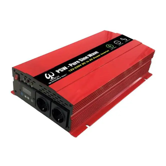
1. Overview The Pure Sine Wave (PSW) inverter provides a 230V supply which closely replicates the domestic mains supply. This makes it ideal for powering more sensitive equipment which may not be compatible with traditional Modified Sine Wave (MSW) inverters. Pure Sine Wave (PSW) 2. - Page 4 CAUTION There may be sparks produced when making battery connections, ensure no flammable materials are present. Incorrect connection of cables to the battery (reverse polarity) may damage the unit and is not covered by the warranty. Single Battery System Supplied cables Inverter Inverter...
- Page 5 Fig3 – Example RCD installation CAUTION It is recommended the inverter is wired and tested by a qualified electrician Remote Mounting LCD Display (1000/2000/3000W Models) For installations where the inverter may be inaccessible, the LCD display can be removed from the inverter and mounted remotely using the optional LCD Frame Kit (WINVFRM) Ensure that the inverter power on/off switch is in the OFF (0) position.
- Page 6 Adding an LCD Display (600W Model) An LCD display can also be added to models without this function by using the optional LCD Display & Frame Kit (WINVLCD) Connect 6 metre extension lead to display port on inverter Fit frame where display is required and attach 6 metre cable to rear Snap fit endplates to cover screw fixings Turn the power on/off switch to the ON (I) position.
-
Page 7: General Information
5. General Information Continuous & Surge Power A Continuous rating is the amount of power the inverter can handle for a number of hours without overloading. The Surge rating is a brief burst of power the inverter can provide to help start certain types of load. - Page 8 Information Mode Various information modes are available by pressing buttons to move forward or backwards through the screens. DC Voltage DC Current AC Voltage Output Wattage Hours Remaining DC Voltage Input voltage available from the battery supply. DC Current Input current being used from the battery supply in order to power the load.
- Page 9 Setup Mode The inverter can be configured by entering the setup mode To enter Setup Mode press & hold key Press keys to select item then press , chosen setting will then flash Adjust setting using then press to set Press and hold ...
- Page 10 Indicator & Error modes Power Illuminates green to show the unit is switched on and power is available from the AC output socket(s) Overload Illuminates red if the units has been overloaded due to excessive current or a short circuit Over Temperature Illuminates yellow if the unit has overheated Audible Alarm...
-
Page 11: Specifications
10. Specifications Part No. PSW-600 PSW-1000 PSW-1000 PSW-2000 PSW-2000 PSW-3000 Voltage Cont Power Rating 600 watts 1000 watts 2000 watts 3000 watts (up to 12 hrs) Peak Power Rating 1200 watts 2000 watts 4000 watts 6000 watts (up to 200ms)
Need help?
Do you have a question about the PSW-600 and is the answer not in the manual?
Questions and answers