
Subscribe to Our Youtube Channel
Related Manuals for Frontier EGA/PY-3030D

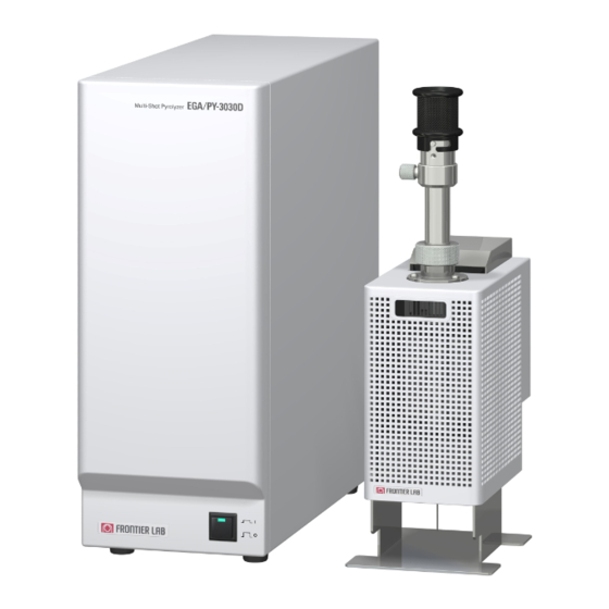
Summary of Contents for Frontier EGA/PY-3030D
- Page 1 Ver.1.36 MULTI-SHOT PYROLYZER MODEL EGA/PY-3030D OPERATION MANUAL www.frontier-lab.com...
-
Page 2: Before Using This Pyrolyzer
Physical appearance and specifications are subject to modifications without notice. PRODUCT WARRANTY Frontier Laboratories Ltd. warrants this product against defects or failures in accordance with the warranty terms and conditions stipulated in a separate sheet. The product warranty can also be downloaded from our website. -
Page 3: For Your Safety
If this product is used in a manner not instructed in this manual, the protective functions of this product may not be activated. Frontier Laboratories Ltd. will not be responsible for losses incurred due to the neglect of these precautions and warnings. - Page 4 Risk of electrical shock. Do not remove the temperature controller WARNING housing cover, unless you are a service engineer certified by Frontier Laboratories Ltd.. If dust is deposited on the power code plug or the cable connectors, clean them thoroughly. Be sure to unplug the power WARNING code.
-
Page 5: Contents In The Package
CONTENTS IN THE PACKAGE A - 5 Ver.1.36... - Page 6 A - 6 Ver.1.36...
-
Page 7: Table Of Contents
CONTENTS IN THE PACKAGE ······················································································· TABLE OF CONTENTS ·································································································· CHAPTER 1 ABOUT MULTI-SHOT PYROLYZER ······························································ 1.1 BACKGROUND OF DEVELOPMENT ···················································································· 1-1 1.2 FEATURES OF EGA/PY-3030D ··························································································· 1-3 1.3 PERIPHEREAL DEVICES ··································································································· 1-4 1.4 SCHEMATIC OF MULTI-SHOT PYROLYZER FURNACE ·························································· 1-5 CHAPTER 2 SPECIFICATIONS ······················································································... - Page 8 3.8.1 Connecting Auto-Shot sampler (AS-1020E) ···································································· 3-6 3.8.2 Connecting other peripheral devices ·············································································· 3-6 3.9 INSTALLING CONTROL SOFTWARE ··················································································· 3-7 3.9.1 Installing USB serial communication device driver ···························································· 3-7 3.9.2 Installing control software ···························································································· 3-8 3.9.3 Setting COM port ······································································································· 3-8 3.10 FRONT, BACK, SIDE, AND TOP VIEWS ·············································································...
- Page 9 6.2 REGULAR MAINTENANCE ································································································· 6-9 6.2.1 Pyrolyzer furnace ········································································································ 6-9 6.2.2 GC injection port ········································································································· 6-10 6.2.3 Temperature Controller ································································································ 6-10 6.2.4 When not in use for a long period of time ········································································· 6-10 6.2.5 List of recommended replacement parts ·········································································· 6-11 6.2.6 Periodic maintenance and inspection ··············································································...
-
Page 10: Chapter 1 About Multi-Shot Pyrolyzer
Py-GC techniques essential in virtually every type of laboratory. Historically, data obtained using Py-GC has suffered from poor reproducibility and poor recoveries of reactive compounds. Frontier Laboratories has overcome these shortcomings by designing a system based on a technique developed by Emeritus Professor Shin Tsuge of Nagoya University. Professor Tsuge’s technique utilizes a small cup. - Page 11 Double-Shot pyrolyzer PY-2020iD. Four years of research has led to the development of the Multi-Shot pyrolyzer EGA/PY-3030D. The Multi-Shot pyrolyzer EGA/PY-3030D is based on a proprietary high temperature resistant ceramic heater with very low heat capacity.
-
Page 12: Features Of Ega/Py-3030D
1.2 FEATURES OF EGA/PY-3030D The features of the EGA/PY-3030D pyrolyzer are summarized below: 1. Operational temperature range: ambient +10ºC to 1,050ºC. 2. A low mass, high temperature ceramic heater rapidly heats and cools 3. Performance guaranteed in both the EGA and Single-Shot modes. -
Page 13: Periphereal Devices
MS search software which facilitates the rapid and in-depth characterization of polymeric materials. In support of the search engine, Frontier offers a host of polymer/additives libraries. Table 1 lists the various peripheral devices designed to be used with the EGA/PY-3030D pyrolyzer. -
Page 14: Schematic Of Multi-Shot Pyrolyzer Furnace
1.4 SCHEMATIC OF MULTI-SHOT PYROLYZER FURNACE Sampler Purge valve Double O-ring Cooling fan Screw Carrier gas Sample cup standby position Quartz pyrolysis tube Cooling gas Ceramic heater Sample cup dropped position ITF heater block Heat sink adapter ITF needle GC injection port Separation column Fig. -
Page 15: Chapter 2 Specifications
When operating at 800°C or higher, keep the operation time less than 20 minutes. If it is operated at 800°C or higher for a prolonged period time, contact us at cs@frontier-lab.com. When the pyrolyzer is in a standby state, we recommend that the furnace temperature should be kept below 200°C. - Page 16 Multi-Shot pyrolyzer EGA/PY-3030D 4. Standard accessories Quartz pyrolysis tube 2 pcs Ultra ALLOY capillary column 5% diphenyl 95% dimethylpolysiloxane, L=30 m (i.d.=0.25mm), df=0.25 µm 1 pc Capillary tube for evolved gas (UADTM, deactivated tube, L=2.5 m, i.d.=0.15 mm) 1 pc...
-
Page 17: About Cooling Time Of Pyrolyzer Furnace
Other requirements and utilities 1) Gas chromatograph (with a split/splitless injection port): some limitations in installation depending on GC model. 2) Multi-shot pyrolyzer: pyrolysis furnace cooling gas (nitrogen or compressed air, pressure: 400-600kPa) supplied via o.d. 1/8 in or 3 mm pipe (cupper or stainless steel), readily accessible from the temperature controller of pyrolyzer (operating flow rate: 7 L/min) 3) Power outlet: AC100/120V or AC200/240V, 400W (MAX) with 3P socket 4 ) Control PC: A PC running Windows 10, 8.1, 8, 7, Vista, or XP operating system with a USB port. - Page 18 The relationship between air flow rate and air pressure is shown in Fig. 2.2. Air flow rate ( L/min ) Air flow rate ( L/min ) P: Air pressure ( KPa ) P: Air pressure ( KPa ) Fig. 2.2 Relationship between air flow rate and air pressure 2 - 4 Ver.1.36...
-
Page 19: Chapter 3 Installation
CHAPTER 3 INSTALLATION In this chapter, the overview of the installation process is described. For detailed installation instructions, consult the installation manual that comes with the installation kit for your GC model. 1. For your safety, wear protective goggles to protect your eyes during operation. -
Page 20: Pumping Down Ms (For Saving Installation Time)
3.1.2 Pumping down MS (for saving installation time) It is recommended that the GC/MS be shut down during the installation of the pyrolyzer; however, to save time, the installation may be performed while the MS is pumping down. If you have a Vent-free GC/MS adapter, install it first, pump down the MS and start the pyrolyzer installation. -
Page 21: Setting Up Gc Injection Port
3.3 SETTING UP GC INJECTION PORT 3.3.1 Replacing septum nut of GC injection port The GC specific installation kit includes a septum nut for the GC injection port, a needle guide, and heat sink that is attached to the pyrolyzer. The septum attached to your GC is replaced with the one in the kit. -
Page 22: Connecting Temperature Controller
3.5 CONNECTING TEMPERATURE CONTROLLER 3.5.1 Connecting power cable to outlet Use only a power outlet with a ground terminal and correct voltage specified. Required power can be found near the power cable connector on the rear panel of the temperature controller. Also, ensure that the power requirement for the pyrolyzer is met by checking the pyrolyzer rear panel. -
Page 23: Connecting Furnace Purge Gas Tube
3.7 Connecting furnace purge gas tube By streaming an inert gas such as N2 through the furnace purge gas tube (see below), oxygen in the furnace is purged and temperature sensor and other parts in the furnace is protected from oxidative degradation. -
Page 24: Installing Peripheral Devices
3.8 INSTALLING PERIPHERAL DEVICES See also the instruction in the operation manual that comes with the peripheral device. All of peripherals of Multi-Shot Pyrolyzer require a 100-115VAC power supply. The power outlets marked “100 / 115VAC OUT, 100W” on the rear panel of the temperature controller can be used to power each peripheral. -
Page 25: Installing Control Software
1. Make sure that the USB cable is properly connected. The PC screen will display a “Found New Hardware” window when the temperature controller is turned ON. 2. Place the CD-ROM (EGA/PY-3030D control software) in the CD drive. (in the example below, CD drive is assigned to D: drive.) 3. -
Page 26: Installing Control Software
3.9.2 Installing Control software A password is required to install the control software. It is obtained through the Frontier Labs web page. For details about how to obtain the password, read the description contained on the CD-ROM software package. 1. Insert the “EGA/PY-3030D control software” CD-ROM into the CD drive of your PC. - Page 27 Fig. 3.7 Resetting COM port number 3 - 9 Ver.1.36...
-
Page 28: Pyrolyzer
3.10 FRONT, REAR, SIDES, AND TOP VIEWS 3.10.1 Pyrolyzer Views from different angles of the pyrolyzer are shown in Fig 3.8. Side view Front view Rear view Cooling fan Liquid Sampler Carrier gas tube Sampler base Cooling gas Inlet port Sampler base fixing Cable connectors screws... -
Page 29: Temperature Controller
3.10.2 Temperature controller The front and back panels of Temperature controller are shown below in Fig. 3.9. Connect M u l t i - S h o t P y r o l y z e r E G A/ P Y - 3 0 3 0 D pyrolyzer RS-232C HEATER... -
Page 30: Chapter 4 Using Control Software
4.1 START UP AND SCREEN LAYOUT 4.1.1 Starting program From the Start menu, select [Programs] - [EGA/PY-3030D Control]. The start-up screen shown in Fig. 4.1 is displayed, followed by the set-up screen shown in Fig. 4.2 Fig. 4.1 Start-up screen for the EGA/PY-3030D Control software Fig. -
Page 31: Screen Layout
4.1.2 Screen layout Fig. 4.3 shows the Double-shot screen of the operating software. A. Title bar B. Menu bar C-1 C-2 C-3 C-4 C. Toolbar I. Start / Stop button E. Pyrolyzer set-up area J. Monitoring area F. Accessories set-ups G. - Page 32 Select a mode for interface control. If “Manual” is selected, the temperature is E-4: controlled at the one set using E-3. If “AUTO” is selected, the interface temperature is maintained 100°C above the pyrolyzer furnace temperature; however, the temperature set by E-3 is the upper limit temperature. F.
-
Page 33: Before Starting An Analysis
4.2 BEFORE STARTING AN ANALYSIS Before starting an analysis the system configuration (e.g., Selective Sampler, MicroJet Cryo-Trap, etc.) must be entered into the system. Set the interface temperature and its control mode according to the procedure described below. 4.2.1 System Configuration 4.2.1.1 Selecting a device or devices Click on “Settings”... - Page 34 Gas Selector (CGS-1050Ex) is highly recommended. The procedure for performing an automated sequence of analysis in air is described below. Manual operation requires in-depth professional knowledge and extensive experiences. Contact us if assistance is needed (cs@frontier-lab.com). (1) “Check” the checkboxes for MicroJet cryo-Trap and Selective Sampler - see Fig. 4.5.
-
Page 35: Set-Up Interface Temperature
4.2.2 Set-up the interface temperature The interface temperature can be set to either the “Auto” or “Manual” mode. In the “Auto” mode, the interface temperature is automatically controlled based upon the pyrolyzer furnace temperature; on the other hand, in the “Manual” mode, it is always controlled at the selected temperature. These modes are entered - see E-4 of Fig. -
Page 36: Set-Up Analytical Modes And Operation
4.3 SET-UP ANALYTICAL MODES AND OPERATION Four analytical modes: Single-Shot Analysis, Double-Shot Analysis, Direct EGA Analysis, Heart-Cut EGA Analysis are available. 4.3.1 Set-up for Single-Shot Analysis and operation procedure From the menu bar, select “Tool” – “Analytical Modes” – “Single-Shot Analysis”, or click on the “Single-Shot Analysis”... - Page 37 (1) “Check” the Furnace and Interface checkboxes (B) to turn the heaters ON. (2) Type in a furnace temperature in C, and allow it to stabilize. (3) Enter a desired time in D. if the Selective Sampler is used, the sample vapors formed during the time defined in D after the “Start”...
-
Page 38: Set-Up For Double-Shot Analysis And Operation Procedure
4.3.2 Set-up for Double-Shot Analysis and operation procedures From the menu bar, select “Tools” – “Analytical Modes” – “Double-Shot Analysis” or click on “Double-Shot Analysis” icon (A) on the toolbar. The set-up screen shown in Fig. 4.9 is displayed. In this analysis mode, thermal desorption (TD) and pyrolysis (PY) can be performed sequentially. - Page 39 (5) Place a sample in a sample cup and attach it to the Pyrolyzer. When using a Double-Shot sampler the dead space is purged by loosening the air purge nut on the sampler as shown on page 1-5. Tighten it after two minutes. During this period, the GC may generate warning sounds if the carrier gas is controlled by EPC, but if it is within 5 min, the GC will NOT power down.
- Page 40 (11) When the GC sends a READY signal, the dialog box shown in Fig. 4.12 will be displayed. Manually press the sample cup drop button at the top of the sampler. After the sample cup drops into the furnace, immediately click the “Start” button on the dialog box or hit “ENTER” key on the PC keyboard.
-
Page 41: Set-Up For Direct Egat Analysis And Operation Procedure
4.3.3 Set-up for Direct EGA Analysis and operation procedure In this analysis mode, an EGA capillary tube (part No.: UADTM-2.5N), is used to connect the GC injector to the detector. Also, the GC oven temperature is set between 250 and 300°C (isothermal) From the menu bar, select “Tools”... - Page 42 STEP 1 STEP 2 STEP 3 STEP 4 TEMP (°C /min) /min) Time (min) (min) Fig. 4.15 EGA Multi-step heating program (5) Place a sample in a sample cup and attach it to the sampler. Attach the sampler to the pyrolyzer and wait two minutes in order to purge the air in the dead space before proceeding.
-
Page 43: Set-Up For Heart-Cut Ega Analysis And Operation Procedure
Heart-cut EGA analysis requires a Selective Sampler. If low boiling components below C are to be analyzed, a cryo trap is required. Frontier Labs MicroJet Cryo-Trap is recommended. Heart-Cut EGA analysis is based on evolved gas curve (EGA thermogram) obtained by Direct EGA Analysis. - Page 44 From the menu bar, select “Tools” – “Analytical Modes” – “Hear-Cut EGA Analysis” or click on the icon for “Heart-Cut EGA Analysis (A) on the toolbar. The set-up screen shown in Fig. 4.18 is displayed. (1) Check the checkboxes for Furnace and Interface (B) to turn on heaters. (2) Type in the parameters for a heating program in the table marked by C, in the same manner as described for Direct EGA analysis.
- Page 45 This completes the operational sequence for a Heart-Cut EGA analysis. Fig. 4.20 below shows the schematic diagram for a series of operational events as described above. Zone D Final (°C) Rate Zone C Final (°C) Rate Zone B Final (°C) Zone A Final (°C) Rate Zone A Initial (°C)
-
Page 46: Other Functions
4.4 OTHER FUNCTIONS 4.4.1 Saving/loading analysis set-ups The set-up methods can be saved using a filename. When all the set-ups are completed, choose “File” – “Save As”, and type in a filename to save the set-ups in a file. As shown in Table 4.1, a suffix is added automatically to the filename. - Page 47 Fig. 4.22 Screen shot of temperature calibration of pyrolyzer and other set-ups 4.4.2.1 Temperature calibration of pyrolyzer furnace The temperature calibration of the pyrolyzer furnace is done by entering the actual temperature measured by other means. Because the pyrolyzer furnace temperature greatly influences analytical results, you should familiarize yourself with this operation and verify the calibration on a periodic basis.
- Page 48 ºC ºC Thermocouple Sample cup Thermocouple Sample cup Pyrolyzer temperature gauge Fig. 4.23 Measurement of actual temperature using thermocouple 4.4.2.2 Other set-ups for Pyrolyzer furnace The temperature display can be switched between the first decimal place and integer. The equilibration time between the time for the furnace and interface temperatures to reach the set points and the time before starting the next operation can be changed.
-
Page 49: Printing Set-Ups
4.4.3 Printing set-ups Set-ups saved in the currently loaded file can be printed. Go to the menu bar, select “File” – “Print”. 4.4.4 Set-up the Py Conditioning Table From the menu bar, choose “Tools” – “Py Conditioning Table”. The Py conditioning table shown in Fig. 4.24 is displayed. -
Page 50: Chapter 5 Four Analysis Methods And Sample Preparation
CHAPTER 5 FOUR ANALYSIS METHODS AND SAMPLE PREPARATION Four analysis methods (Single-Shot, Double-Shot, evolved gas analysis, and Heart-Cut EGA analysis) are described. Refer to Chapter 4 for details about settings and operations. Sampling techniques are also described here. 5.1 SINGLE-SHOT ANALYSIS This method is also called flash pyrolysis. - Page 51 STEP3 Prepare the sample (1) Place 5 µL of the sample in an Eco cup SF and evaporate the solvent. (2) Attach a stick (Eco stick SF) to the sample cup and fix the assembly to the sampler. Position the slider of the sampler in the down position. Attach the sampler to the pyrolyzer and wait for 1 min.
-
Page 52: Evolved Gas Analysis (Ega)
5.2 EVOLVED GAS ANALYSIS (EGA) When a polymeric sample is heated, volatile components contained in the polymer are released and ultimately, the polymer is degraded. The result is a plot of sample temperature vs. detector response. Such a plot has been termed a ‘thermogram’. The thermogram provides an indication of the sample complexity. - Page 53 STEP3 Loading sample Place 5 µL of the sample into an Eco cup SF and evaporate the solvent Attach a stick (Eco stick SF) to the sample cup and fix it to the sampler. Push the slider of the sampler down and attach the sampler to the pyrolyzer. Wait for 1 min (Fig. 5.5A). Click the “START”...
-
Page 54: Double-Shot Analysis
5.3 DOUBLE-SHOT ANALYSIS This is a two-step analysis in which volatiles are analyzed using thermal desorption technique, and the residual polymeric fraction is then pyrolyzed. A typical instrument configuration for the Py-GC/MS is shown in Fig. 5.1. The sample is the supplied polystyrene solution. The analytical conditions for thermal desorption and flash pyrolysis are determined using the EGA thermogram shown in Fig. - Page 55 STEP5 Flash pyrolysis When the GC analysis of the thermally desorbed compounds is completed and the “Ready for pyrolysis” dialog box is displayed, press the sample drop button located at the top end of the sampler to drops the sample cup to the furnace. Now, immediately click “Start” button to start the GC analysis.
-
Page 56: Heart-Cut Analysis
Selective Sampler (optional). Also for analysis of low boiling evolved gases with C or less requires a cryo trap. Frontier Laboratories MicroJet Cryo-Trap is highly recommended. The setup for a typical Heart-Cut EGA analysis is shown in Fig. 5.9. By using the Selective Sampler and MicroJet Cryo-Trap, a maximum of eight temperature zones can be automatically analyzed by GC/MS. - Page 57 STEP1 Instrument set up Attach Selective Sampler and separation column. STEP2 Setting analytical conditions for pyrolyzer and GC (see Fig. 5.11) Set ITF TEMP to “Auto” mode. Set the furnace temperature and others in “Heart-Cut EGA Analysis” screen. STEP3 Loading sample (1) Weigh out sample and place it in an Eco cup SF.
-
Page 58: Sample Preparations
5.5 SAMPLE PREPARATIONS In the Single-Shot analysis (flash pyrolysis) using Py-GC/MS, a sample form, shape and condition affect results as well as the reproducibility. If the sample is soluble in a solvent, it is recommended to dissolve it in the solvent, place in a sample cup, and evaporate the solvent to form a film on the surface of the sample cup. - Page 59 A2) Using pulverizing tool (Polymer Prepper from Frontier Laboratories Ltd.) Using a Polymer Prepper (a nickel coated special file), fine powers with the particle size of 0.1 mm can be prepared easily and rapidly.
-
Page 60: Selection Of Sample Cups And Sticks
5.6 SELECTION OF SAMPLE CUPS AND STICKS The types of Eco-cups and Eco-sticks are selected from Table 5.1 depending on your analytical purpose and the technique that you use. Eco-cups and Eco-sticks are made of stainless steel; the entire surface has been deactivated by coating with fused silica on the surface. -
Page 61: Chapter 6 Maintenance
The three components which need attention are the sample cups, the quartz pyrolysis tube, and the interface needle. On the support page of the Frontier Lab’s web site, several maintenance videos are available for your viewing. These how-to videos will help you perform maintenance procedures. Please visit our web site at www.frontier-lab.com. - Page 62 6.1.1.2 Cleaning by red-heating This is very simple and works well in most cases. (1) Remove all the residues left in the cup using a cotton swab. When using a pair of tweezers, do not scratch the inner surface of the sample cup. (2) As shown in Fig.
-
Page 63: Replacing And Cleaning Quartz Pyrolysis Tube
Frontier Laboratories recommends that the liner be inspected after 200 injections or whenever there is a loss of analytical precision. The instruction for replacing the contaminated pyrolysis tube with a new one is provided below. - Page 64 (4) Remove ITF union N using a 12 mm wrench. The ITF union and pyrolysis tube may stick together. When this happens, heat the ITF union with a torch to detach the pyrolysis tube from interface needle. If the ITF union is separated from the pyrolysis tube, remove the liquid sampler located at the top of the pyrolyzer.
- Page 65 (8) Tighten the ITF union slowly about 1/4 turn using a 12 mm wrench. The amount to be tightened depends on the tolerance of the pyrolysis tube and graphite Vespel ferrule. (9) Attach the heat sink adapter. Secure the adapter so that there is no large gap between the adapter and interface block.
- Page 66 6.1.2.2 Solvent cleaning When a large amount of material is pyrolyzed, the upper part of the tube (A in Fig. 6.2) may be contaminated with high boiling compounds. After cooling the furnace to room temperature, the contamination is removed by rubbing the inner wall of the tube with a cotton swab dampened with a solvent as shown in the figure below.
-
Page 67: Interface Needle
6.1.3 Interface needle (ITF needle N) The end of the interface needle is very sharp. When handling the CAUTION needle, wear protective gears such as safety goggles for your safety. 6.1.3.1 Clogging by sample contamination Needle contamination consists of mostly tars and stained tars. The most effective way to clean a contaminated needle is to sonicate it in an appropriate solvent. -
Page 68: Gc Injection Port
6.1.4 GC injection port 6.1.4.1 Septa When the pyrolyzer is installed on a GC, the injection port is in close contact with the heat sink adapter; therefore, the temperature of the septum is at least 50°C higher than its normal operating temperature. -
Page 69: Regular Maintenance
After cleaning, a lubricant must be applied. Contact us if you prefer it to be re-conditioned at Frontier Labs (charged). b) Check the O-ring for air purge valve for any damage. The damage can lead to gas leakage. -
Page 70: Gc Injection Port
If there is any problem, the sample cup chuck (PY1-1345) needs to be replaced with a new one. This is customer serviceable, contact your nearest sales office or Frontier Laboratories. (4) Sampler base Contamination or damage of the O-rings (P-12, P/N: PY1-7811) at the sampler base may result in gas leakage. -
Page 71: List Of Recommended Replacement Parts
M30 is replaced. Needle set N PY1-1274 As needed Over tightening injector septum may clog needle opening with septum debris. Standard accessory for EGA/PY-3030D ITF union N PY1-3513 1 year Pyrolyzer Used when Auto-Shot sampler is used. -
Page 72: Chapter 7 Troubleshooting
Symptoms, causes, and their solutions are summarized below. If your problem persists after implementing the suggested solutions, or if you experience problems not addressed here, contact your nearest sales office or contact Frontier Laboratories directly: www.frontier-lab.com. 7.1 PYROLYZER FURNACE SYMPTOM... - Page 73 GC and turn carrier background) gas ON. Set the oven temperature to 40ºC and hold for 30 min then raise the temperature at 10ºC /min until dry. If column is not Frontier Labs’ Ultra ALLOY column, contact column manufacturer. Ver.1.36...
-
Page 74: Temperature Controller
Tube cracks in lengthwise Fixed the upper part in the state that a quartz direction. pyrolysis tube was not inserted in properly to the depths and might tighten up ITF union. To The sampler base is fixed see an instruction manual, please confirm with screws while the quartz whether a quartz pyrolysis tube is attached pyrolysis tube is not inserted... -
Page 75: Typical Troubleshooting Procedure
7.3 TYPICAL TROUBLESHOOTING PROCEDURE The two most prevalent problems encountered when using the pyrolyzer are gas leaks (at the needle interface) and a clogged ITF needle. Here are some examples of the symptoms associated with these two problems: ・ Background peaks in the MS spectrum have a high abundance of m/z 28 and 32. ・... - Page 76 The carrier gas total flow is unstable and eventually goes to zero. ・ When the sampler is removed from the pyrolyzer a gas releasing sound is heard. If your problem persists contact your nearest sales office or Frontier Laboratories: www.frontier-lab.com Ver.1.36...
-
Page 77: List Of Error Codes From Cotrol Software
7.4 LIST OF ERROR CODES FROM CONTROL SOFTWARE ERRO NO./DISPLAY CAUSE SOLUTION/CHECK POINTS Check to see if the cable from the pyrolyzer is 1. Heater Heater not powered properly connected to the POWER connector located on the rear of controller. [Furnace or Interface] Make sure the cable from the pyrolyzer is properly connected to the SENSOR connector... -
Page 78: Chapter 8 Guarantee Of Basic Performance (Reproducibility)
Reproducibility (expressed as the %RSD of three sequential analyses) of the polystyrene EGA thermogram and the polystyrene pyrogram are guaranteed to meet the following specifications: Evolved Gas Analysis: Frontier Laboratories guarantees that the reproducibility of the apex of the polystyrene peak is ≤0.3% RSD. - Page 79 Peak apex temperature Analytical conditions (RSD ≤ 0.3%, n=3) ITF tube : EGA tube (deactivated metal capillary, L=2.5 m, id.=0.15 mm, no stationary phase) Column flow : 1.0 ml/min Split ratio : 1/100 Oven temp. : 300°C (isothermal) Injector temp. : 300°C Py furnace temp.
-
Page 80: Consumable Parts List
Heat sink adapter kit 3030SA PY1-3551 1 set For EGA/PY-3030D. Used for Agilent7890/6890 and Shimadzu GC-2010 /17A, includes 2 securing screws. For EGA/PY-3030D. For PE Auto system/Clarus GC, includes 2 securing Heat sink adapter kit 3030PE PY1-3552 1 set screws. - Page 81 PY-K303D 1 set Eco-cup SF, Eco-cup LF, Eco-stick SF, Eco-stick DF, Eco stand AL, Quartz pyrolysis tube A30, Needle set N, 6 mm graphite Vespel ferrule, Eco-pickup F, ( for EGA/PY-3030D) Septum (for liquid sampler) Consumables set 3030S PY-K303S 1 set...
- Page 82 PYROLYZER MAJOR CONSUMABLE PARTS Major consumable parts are visually illustrated with part names (part numbers, quantities). O-ring(P-12) O-ring(P-6W) (P/N: PY1-7811, 10 pcs) (P/N: PY1-2017, 20 pcs) Quartz pyrolysis tube A30 (P/N: PY1-3018A, 1 pc) Heat Sink Adapter Used for Agilent and Shimadzu(P/N: PY1-3551, 1set) Used for Thermo Fisher(P/N: PY1-3555, 1set)...
-
Page 83: List Of Optional Products
LIST OF OPTIONAL PRODUCTS A variety of optional products are available for you to better use Frontier Laboratories Multi-Shot or Single-Shot pyrolyzers. Contact your nearest sales office or Frontier Laboratories for details. Product No. Product name Description PY-1010E Selective Sampler The device introduces gases eluted from pyrolyzer in any temperature zone into a separation column, utilizing gas pressure difference at the column inlet.
Need help?
Do you have a question about the EGA/PY-3030D and is the answer not in the manual?
Questions and answers