
Related Manuals for ThermoProbe TP9-A


Summary of Contents for ThermoProbe TP9-A
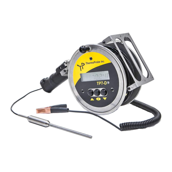
- Page 1 TP7-D ANUAL TP9-A Thermoprobe Models TP7D and TP9A 1.800.561.8187 information@itm.com www. .com...
- Page 2 EU Declaration of Conformity according to directive 2014/34/EU (ATEX) Thermoprobe, Inc. hereby declares the TP7-D and TP9-A products to be in accordance with the following standards and directives: Name and address of Manufacturer ThermoProbe, Inc. 112A Jetport Dr. Pearl, MS 39208 USA...
-
Page 3: Replacing Battery
AA (LR6) Alkaline LR6XWA GP (Gold Peak) AA (LR6) Alkaline GP15A AUTHORIZED REPAIR It is recommended that service beyond the scope of this manual be performed by ThermoProbe, Inc. or one of its authorized distributors. 05/2021, JK 1.800.561.8187 information@itm.com www. -
Page 4: User Interface
USER INTERFACE Power/Select Button Up/Down Menu Buttons Up/Down Menu Buttons Icons for Memory readings Temperature indicating arrows Indicators for Low battery indicator calibration points Power Button Pressing the Power button once will turn on the device. (Note: The instrument will automatically power off 20 minutes after the last button push.) Pressing and holding the “Power”... -
Page 5: Usb Memory
Backlight When the instrument is operating in low-light conditions a photocell will detect this situation and turn the backlight Temperature Logging It is necessary for the temperature to be stable before logging temperature. The display arrows will flash 3 times when the temperature reading has stabilized. -
Page 6: Probe Types
The TP7-D or TP9-A can use either 2-wire or 3-wire probe assemblies. ThermoProbe replacement probe assemblies are available in different configurations. The cable length is available in lengths up to 50 meters or 165 feet. Standard brass markings are available applied in 5 feet or 1 meter increments. The sensors are available with 4 weight types. -
Page 7: Calibration Procedure
CALIBRATION PROCEDURE The calibration mode should only be accessed by qualified personnel with proper equipment; otherwise calibration integrity may be compromised. Read the following instructions carefully. At least 2 points are required to make an adjustment. (2-Point calibration). Additional points can be taken (3-Point or 4-Point calibration) to calibrate a large range of temperatures (e.g. - Page 8 The device is now in adjustment mode. The display will show PT1. The “up/down” buttons can be used to select a different point to adjust or CANCEL. If the CANCEL option is chosen then the calibration procedure is exited and the prior calibration values are re-activated. = Lowest temperature point ADD PT1 ADD PT2...
- Page 9 Exchange of components other than the batteries may compromise ATEX/IECEx or other certifications and shall only be undertaken by ThermoProbe or one of its qualified service providers. See also “Authorized Repair” section. g) To reduce the risk of fire or explosion, this device must be bonded to the vessel according to clause 6.3.2 e), IEC/EN 60079-14 before and during introduction into the vessel and shall remain bonded until the sensor probe is completely withdrawn from the vessel.
-
Page 10: Intrinsic Safety
Batteries must not be mixed with batteries of other models or manufacturers. Batteries must not be installed with polarity reversed where one cell could charge another cell. CERTIFIED Batteries for the TP9-A and TP7-D are as follows: Manufacturer Type...
Need help?
Do you have a question about the TP9-A and is the answer not in the manual?
Questions and answers