Table of Contents
Advertisement
Quick Links
Advertisement
Table of Contents

Related Manuals for LNI NitroGen Series

Summary of Contents for LNI NitroGen Series
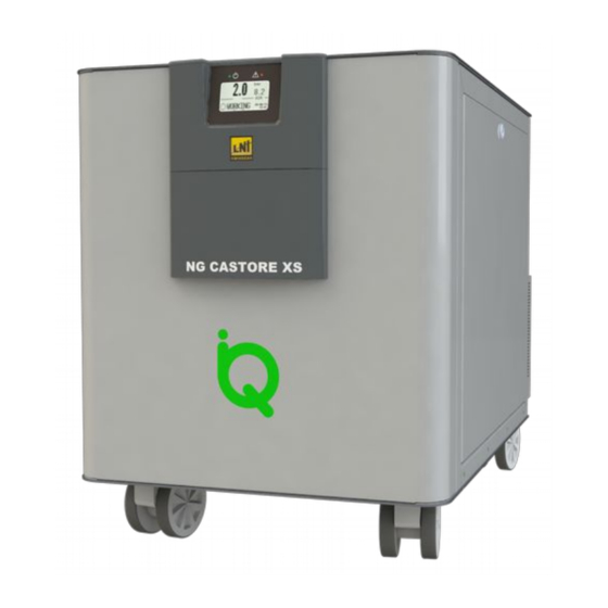
- Page 1 NitroGen Series NG CASTORE XS iQ NGA CASTORE XS iQ Operating manual 10/2021 LNI Swissgas LNI Swissgas srl www.lni-swissgas.eu Registered office: Via Sassoferrato 1, 20135 Milano MI info@lni-swissgas.eu Logistics centre: Via E. Mattei 9, 35038 Torreglia PD...
-
Page 2: Table Of Contents
Table of contents 1 General informations........................1 1.1 Symbols and terminology........................1 1.2 General warnings..........................2 1.3 Safety information...........................2 1.4 Intended use............................3 1.5 Improper use...........................3 1.6 Reference directives........................3 1.7 Disposal............................3 2 Description of the appliance.....................4 2.1 Operating principle..........................4 2.2 Identification of the models......................4 2.3 Technical specifications........................5 2.3.1 Operating and storage conditions.......................5 2.3.2 NG CASTORE XS iQ –... - Page 3 8.2.6 Remote contact............................30 8.3 Date/Time Setting..........................31 8.4 Backlight Time..........................31 8.5 History............................31 8.6 Diagnostics............................32 8.7 Counters............................32 9 Maintenances........................... 33 9.1.1 Preventive checks and maintenances.......................33 9.2 NG CASTORE XS iQ (working @ 80% of its maximum power)...........34 9.2.1 Note:................................34 9.2.2 Replace the Compressor air intake filter and N2 stage filters..............35 9.3 Service Menu..........................36 10 Alarms and pre-alarms......................
-
Page 4: General Informations
1 General informations Symbols and terminology In the unit and in this manual are used some symbols to signal to the user one or more information. Consult the user manual in all cases where this symbol is marked on the equipment in order to find out the nature of the potential hazard and any actions which have to be taken to avoid them. -
Page 5: General Warnings
General warnings Before using the appliance, users must read and understand the contents of every section of this manual The descriptions, drawings and photographs contained in this manual are purely indicative and in some cases may not reflect the actual appliance purchased ... -
Page 6: Intended Use
Intended use The nitrogen generator is designed to produce nitrogen for laboratory use. The appliance must only be used for this purpose, in compliance with the specifications and instructions described in this manual. In particular, special attention must be paid to the following warnings: ... -
Page 7: Description Of The Appliance
2 Description of the appliance Operating principle NG CASTORE XS iQ Inlet filter Membrane Filter Filter dryer membrane Compressor OUTLET #1 OUTLET #2 Optional Purge NGA CASTORE XS iQ SHI Inlet filter Membrane Filter Filter dryer membrane Compressor OUTLET DRY AIR OUTLET Purge The nitrogen generators described in this manual, thanks to its built in scroll-compressor, are able to provide... -
Page 8: Technical Specifications
Technical specifications 2.3.1 Operating and storage conditions Operating and storage conditions Operating temperature 5-35°C (41-95°F) Storage temperature 1-40°C (33.8-104°F) Humidity (max, non-condensing) 80% [5-35°C (41-95°F)] Noise < 50dB(A) Over-voltage category Pollution degree rating 2 (with no aromatic compounds) IP20 Altitude <... -
Page 9: Ng Castore Xs Iq - Full Range Power Supply Voltage
2.3.3 NG CASTORE XS iQ – FULL RANGE power supply voltage Models: NG CASTORE XS iQ N2 outlet Flow rate (Max) 18 l/min 24 l/min 36 l/min Outlet pressure (Max) 8 Bar (116 psi) Nitrogen purity LCMS grade (up to 99.9% Dew point <... -
Page 10: Nga Castore Xs Iq Shi - 220-240 Vac
2.3.4 NGA CASTORE XS iQ SHI – 220-240 VAC Models: NGA CASTORE XS iQ N2 outlet Flow rate (Max) 40 l/min Air & N2 combined Outlet pressure (Max) 8 Bar (116 psi) Nitrogen purity LC-MS grade (up to 99,9%) Dew point <... -
Page 11: Weight And Dimensions
Weight and dimensions 2.4.1 Weight Model Net weight (kg) Gross weight (kg) 220-240 VAC NG CASTORE XS iQ NGA CASTORE XS SHI Full range power supply voltage NG CASTORE XS iQ Table 4: Weight of the various models 2.4.2 Dimensions A = 69 cm 27.2”... -
Page 12: Overview Of The Appliance
Overview of the appliance NG(A) CASTORE XS iQ Figure 1: Overview of the appliance Description Green operating status LED Red alarm or pre-alarm signal LED 128x64 pixel LCD touch-screen with START/STOP button Power connector and switch I/O connector for remote control RS232 serial communication port RS485 #2 serial communication port RS485 #1 serial communication port (RESERVED) -
Page 13: Receiving The Appliance
3 Receiving the appliance On receiving the appliance, carefully check all the parts to ensure that no damage has occurred during transport. Any damage found must be reported to the carrier, specifying the type of damage on the delivery documents. Any claims must be received in writing within eight (8) days from the date of receipt of the goods. -
Page 14: Available Accessories (Not Included, To Be Requested Separately)
4 Available accessories (not included, to be requested separately) In this section will be described some accessories useful for a safety and convenient utilisation of NG- CASTORE-XS-iQ. All these parts are not included by default They can be order and installed later by the operator when their function is considered more suitable and convenient. - Page 15 Overview 6920.71.30 6920.71.40 Description Dry-Air inlet N2 inlet Dry-Air Outlet 1 (GAS1 / GAS2) Dry-Air Outlet 2 (EXHAUST) N2 Outlet Dry-Air 1 pressure gauge (GAS1 / GAS2) Dry-Air 1 pressure regulator (GAS1 / GAS2) Dry-Air 2 pressure gauge (EXHAUST) Dry-Air 2 pressure regulator (EXHAUST) N2 pressure gauge N2 pressure regulator Holes to hang up the regulator box on hooks...
-
Page 16: Installation
5 Installation Installation layout The generator has been designed to avoid excess pressure being created at the outlet; nonetheless, below there is a suggested installation layout. Basic installation Basic installation using Regulator Box 6920.71.30 (2 outlets) Basic installation using Regulator Box 6920.71.40 (3 outlets) Pressure regulators boxes are useful when the application is more than 5 meters farther from the gas source (NG-CASTORE-XS-iQ). -
Page 17: Positioning
Positioning Nitrogen build-up may lead to a lack of oxygen and therefore create the risk of asphyxia. Always make sure all of the openings of the unit are kept clean and free of obstructions. Keep the generator away from heat and flames. ... -
Page 18: Pneumatic Connections
Pneumatic connections The pneumatic connections must be completed with suitable fittings, with the following characteristics: Type of fitting Description 1/4” BSPP male threaded fitting N2 outlet #1 1/4” BSPP male threaded fitting N2 outlet #2 (optional) / Dry Air outlet (NGA-SHI models) 1/4”... -
Page 19: Electrical Connection
Electrical connection All operations involving the electrical parts must only be performed with the unit disconnected and electrically isolated from the power supply. These operations must only be carried out by trained personnel in full compliance with all safety standards. ... -
Page 20: Commissioning
6 Commissioning Starting the appliance the first time Make sure that all of the instructions regarding positioning, air and electrical connections have been followed. Figure 2: Start-up operations Operations list to start the nitrogen generator the first time: Connect the N2 outlet #1 (3) ... -
Page 21: Operation
7 Operation The following descriptions may refer to just one or some of the models specified in this manual. In such cases, the applicable model/models are indicated in brackets. To identify your model of generator, see the identification label affixed to the rear of the appliance. User interface Users can interact with the system using the 128x64 pixel resistive touch-screen display. -
Page 22: Summary Screen
Summary screen Normally, the display shows the summary screen, where users can monitor the most important system values: system status, working pressure, current pressure Swiping to the right or left directly accesses the two diagnostics screens. Pressing any point on the screen for at least half a second accesses the main menu. NG CASTORE XS iQ NGA CASTORE XS iQ SHI Figure 3: Summary screen... -
Page 23: System Status
7.2.1 System status Signal Description The system is off and not in gas production state WORKING The system is in gas production state ALARM The system has detected an operating error and has stopped the gas production The system has detected an error that does not affect gas generation, and the generator PRE-ALARM continues the gas production Table 6: System status... -
Page 24: Serial Communication And Connections
Serial communication and connections 7.4.1 Digital I/Os Attention, every external device connected to the generator must respect the SELV directives. The appliance can be managed and/or monitored via a remote connection. The appliance is fitted with several connectors, with the following functions: ... -
Page 25: Parallel Mode
Parallel Mode 7.5.1 Introduction Parallel Mode is a function used to combine the flow from multiple generators on a single line, in which each appliance contributes in proportion to its capacity. A maximum of 10 appliances can be connected together. 7.5.2 Kit Parallel system control box with LAN, kit (P/N: 6920.71.60) The kit 6920.71.60 includes following items:... -
Page 26: Electrical Connection
7.5.3 Electrical connection Power up the Parallel BOX controller with its power supply adapter. Connect the RS485 port on the spilt box for parallel box controller LAN with RS485 # 2. Perform this operation for each generator. NG-CASTORE-XL 6930.71.001 NG-CASTORE-XL NG-CASTORE-XL 6930.71.001 NG-CASTORE-XL... -
Page 27: System Id Setting
7.5.5 System ID setting In order for the a correct operation of the system, a unique number (ID) must be assigned to each generator. To do this, proceed as follows: Screen Procedure Manually set the unit ID for each Generator (every Generator must have a consecutive number). -
Page 28: Configuration
7.5.8 Configuration • Once connected the parallel Box to the generator, connect it to the PC via USB cable; • If necessary, install the driver to enable the communication vis USB, running the follow program. CDM v2.10.00 WHQL Certified.exe Start the program: PBOX.LAN-configuration-V10.exe Set in the table the same generators number as the ones setted before in the unit and press the button Write to confirm the operation.”1a”... -
Page 29: Menu
8 Menu The touch-screen offers the possibility to access some of the parameters that manage appliance operation via a series of menus. For a detailed description on how to use the touch-screen, see 7.1. To access the main menu, simply touch any point on the touch-screen for half a second when the summary screen is displayed. -
Page 30: Adjust Set Pressure
Adjust Set Pressure The generator is setted by default to produce at a pressure of 7bar (101.5psi). To change this, set the desired pressure value: The first item in the menu is Adjust Set Pressure. From this page is possible to adjust the needed N2 pressure (or AIR). Press the button for at least half a second to enter in the setting screen. -
Page 31: Setup
Setup 8.2.1 Parameter From the Setup submenu, a series of system parameters can be accessed (swiping to the right or left). 8.2.2 List of user parameters Name Description Value 1 Default value Identifies the logical address if connecting the Identifier 1 : 255 unit via an RS485 communication bus Set to “Yes”, when power is restored after a... -
Page 32: Auto Run
8.2.3 Auto Run From the main menu, scroll the screens to the left or right until displaying the Setup submenu. Press the touch-screen for half a second. The Parameter submenu will be displayed. From the Parameter submenu, press the touch-screen for half a second to access the individual parameters (see Table 4: User parameters). -
Page 33: Temperature Unit
8.2.5 Temperature Unit From the main menu, scroll the screens to the left or right until displaying the Setup submenu. Press the touch-screen for half a second. The Parameter submenu will be displayed. From the Parameter submenu, press the touch-screen for half a second to access the individual parameters (see Table 4: User parameters). -
Page 34: Date/Time Setting
Date/Time Setting From the main menu, scroll the screens to the left or right until displaying the Setup submenu. Press the touch-screen for half a second. Scroll to the right or left until the Date/Time Setting submenu is displayed Touching this item for half a second accesses the screen for setting the system date/time Touch the required field for half a second to access the corresponding setting. -
Page 35: Diagnostics
Diagnostics From the main menu, scroll the screens to the left or right until displaying the Diagnostics submenu. Press the touch-screen for half a second to access the 3 diagnostics pages, showing all the values controlled/acquired by the system Cabinet: Cabinet internal temperature (°C, °F) Head comp: Internal compressor’s head temperature (°C, °F) Motor power: Compressor’s motor power consumption (W) Press. -
Page 36: Maintenances
9 Maintenances All of the maintenance operations that involve handling parts of the unit must only be carried out by suitably trained personnel and in full compliance with all safety standards. Moreover, these operations must only be carried out with the unit off, unplugged and electrically isolated. -
Page 37: Ng Castore Xs Iq (Working @ 80% Of Its Maximum Power)
Use only genuine spare parts indicated in this manual. The use of parts not mentioned in this manual will invalidate the warranty. NG CASTORE XS iQ (working @ 80% of its maximum power) Message Type of Spare part Operation to be performed Interval displayed maintenance... -
Page 38: Replace The Compressor Air Intake Filter And N2 Stage Filters
9.2.2 Replace the Compressor air intake filter and N2 stage filters All of the maintenance operations that involve handling parts of the unit must only be carried out by suitably trained personnel and in full compliance with all safety standards. Moreover, these operations must only be carried out with the unit off, unplugged and electrically isolated. -
Page 39: Service Menu
Service Menu The Service Menu is reserved for authorised personnel only. Access to the menu is password-protected. Alarms and pre-alarms During operation, the system carries out several automatic checks. In the event of serious anomalies, the display and the red LED flash quickly, the buzzer sounds rapidly and intermittently, an alarm message is displayed that identifies the problem, and nitrogen production is suspended. -
Page 40: Pre-Alarms
10.2 Pre-alarms Pre-alarm messages help the operator try to solve any problems before an alarm is activated and nitrogen production stops. To mute the buzzer, simply swipe the touch-screen from the top down. Message displayed Cause Solution Compressor head temperature value If the pre-alarm persists, contact Head Temp. -
Page 41: Alarms
10.3 Alarms In the event of serious anomalies, nitrogen production stops, the display and the ALARM LED (red) flash quickly and the buzzer sounds intermittently until the alarm is acknowledged by the user. To mute the buzzer, simply swipe the touch-screen from the top down, or press the START/STOP button. Message displayed Cause Solution... -
Page 42: How To Request Service
How to request service To request service and/or for any further information on operation of the appliance, please contact your local reseller. Operating manual NG(A) CASTORE XS iQ...