Table of Contents
Advertisement
Quick Links
Advertisement
Table of Contents

Related Manuals for COBHAM LGA-5005 HLD


Summary of Contents for COBHAM LGA-5005 HLD
- Page 1 LGA-5005 HLD and Enhanced Low Gain Antenna (HELGA) Installation manual...
- Page 2 LGA-5005 (HELGA) Installation manual Document number: 98-152675-A Release date: 15 December 2020 Cobham Public...
- Page 3 This manual and the drawings and wiring diagrams contained herein may not be used as a substitute for an STC package. The newest versions of Cobham SATCOM user and installation manuals as well as outline drawings can be downloaded from www.cobham.com/satcom, Cobham SYNC Partner Portal. Some material and features are for partners only and can only be accessed after login with a password.
- Page 4 Contact the local distributor for information about what type of return system to use. Record of revisions Rev. Description Release Date Initials Original version 15 December 2020 98-152675-A Cobham Public...
- Page 5 Secure and insulate all cables correctly. Adhere to the minimum bend radius specifications. Hardware installation The installation of the LGA-5005 must not compromise the safety or integrity of the aircraft structure. Take care to prevent any changes to vital aircraft components or structures when installing the antenna. 98-152675-A Cobham Public...
-
Page 6: Table Of Contents
Maintenance intervals ......................4-1 Events generated by the LGA-5005 ..............4-2 Returning units for repair ...................4-3 4.3.1 Return Material Authorization (RMA) ................4-3 Chapter 5 Special tools, fixtures and equipment Chapter 6 Illustrated parts list Appendix A Equipment specifications LGA-5005 specifications .....................A-1 98-152675-A Cobham Public... - Page 7 Table of Contents DO-160 specifications ....................A-2 A.2.1 Qualification Forms ......................A-2 Certification ..........................A-5 A.3.1 Certifying agency ........................A-5 A.3.2 List of (E)TSOs and deviations ..................A-5 Appendix B References References ..........................B-1 Glossary ................................Glossary-1 Index ..................................Index-1 98-152675-A Cobham Public...
- Page 8 Breathing/drainage slots, both sides ......................3-4 Figure 3-4: Fore/aft of the antenna..........................3-5 Figure 3-5: Base of the antenna ............................3-8 Figure 3-6: Sealant application to the bolt access holes of the antenna radome........3-9 Figure 6-1: LGA-5005 – HELGA ............................6-1 98-152675-A Cobham Public...
- Page 9 Table 5-2: List of supplies..............................5-1 Table 6-1: Legend for figure items ..........................6-2 Table A-1: Equipment specifications for LGA-5005....................A-1 Table A-2: Qualification Forms ............................A-2 Table A-3: Common environmental conditions and tests (DO160G) for LGA-5005 ......A-2 98-152675-A viii Cobham Public...
-
Page 10: Chapter 1 About This Manual
• Maintenance Maintenance interval and actions. Repair and servicing. • Special tools, fixtures and equipment • Appendices The appendices contain equipment specifications and a list of references. • Glossary Abbreviations and acronyms • Index 98-152675-A Cobham Public... -
Page 11: Precautions
Some materials can be dangerous. CAUTION! Do not use materials that are not equivalent to materials specified by Cobham SATCOM. Materials that are not equivalent can cause damage to the equipment. CAUTION! The system contains items that are sensitive to electrostatic discharge. -
Page 12: Chapter 2 Introduction
Type Abbreviated Certified OEM PNR Equipment Name Number Name Part Number [for Cobham internal use only] LGA-5005 HLD/Enhanced HELGA 405005-vvccc 677-A0213 Low Gain Antenna Table 2-1: Equipment covered a. Final PNR suffix vvccc: vv = customer specific, ccc = minor variants... -
Page 13: System Overview
(as defined in ARINC 781-6, Attachment 7, Configuration 3 [4]), interconnected as shown in Figure 2-2:. • LGA-5005 HLD/Enhanced Low Gain Antenna (HELGA) • SDU-5045 Compact Satellite Data Unit (CSDU) • SCM-5055 CSDU Configuration Module (SCM) -
Page 14: Interface Of The Lga-5005
• Status link modem signal from LGA-5005 to the CSDU. The interconnection cable design will be specific to the requirements of the aircraft type. The interconnection cable between the antenna and the CSDU may be supplied as part of 98-152675-A Chapter 2: Introduction Cobham Public... -
Page 15: Table 2-3: Coaxial Cable Characteristics
Table 2-3: Coaxial cable characteristics The definition of the electrical signals carried on the cable interface between LGA-5005 and the CSDU is specific to the Cobham AVIATOR-S system. LGA-5005 shall never be interfaced to any avionics other than an AVIATOR-S CSDU [part number 405045-vvccc]. -
Page 16: Chapter 3 Installation
The Design Assurance Level of the LGA-5005 for software and hardware is DAL D. Storage and transportation Store the box in a dry area (< 50% RH) where the temperature is within the range of -55 °C to + 85 °C (- 67 °F and + 185 °F). 98-152675-A Cobham Public... -
Page 17: Unpacking & Initial Inspection
Verify the following during unpacking of the unit: • The connector has a protective cap fitted. Retain the protective connector cap, packing material and containers for future storage and/or shipping use. Chapter 3: Installation 98-152675-A Cobham Public... -
Page 18: Prerequisites
Sealing of the antenna Sealing of the gap between antenna and fuselage skin is an aspect that is determined by customer preference. Cobham does not require the underside of the antenna to be sealed since there is no unprotected metal prone to corrosion. -
Page 19: Figure 3-2: Areas Where No Sealant Is To Be Applied
Mounting foot Mounting foot O-ring sealing area Figure 3-2: Areas where NO sealant is to be applied Figure 3-3: Breathing/drainage slots, both sides Chapter 3: Installation 98-152675-A Cobham Public... -
Page 20: Grounding
(pitch offset). In this manual these are called installation offset angles. The installation offset angles of the LGA-5005 are compensated for by the CSDU, in which case you must measure the yaw-, roll- and pitch-offsets. It is recommended that the 98-152675-A Chapter 3: Installation Cobham Public... - Page 21 In this case a separation distance of at least 0.5 m is adequate to avoid affecting the radiation patterns of the antennas. Closer spacing may be possible; in this case it is advisable to contact Cobham for guidance. Interference-free operation between an Inmarsat-based SATCOM system and other L-band (e.g.
- Page 22 The isolation between the LGA-5005 and a GLONASS antenna should be at least 46 dB. This typically corresponds to a a separation between the antennas of 10 m. The separation distances above are guidelines only, as Cobham has no control over properties of the antennas of other systems. As with all radio systems, ensuring non- interference remains the responsibility of the installation designer.
-
Page 23: Installation Of The Antenna
6. If sealing compound was applied in step 1, remove any excess sealing compound around the antenna periphery and ensure that the breathing/drainage slots are completely clear. 7. Check the maximum torque against the bolt specification and the fuselage or mounting plate structural limitations. Chapter 3: Installation 98-152675-A Cobham Public... -
Page 24: Figure 3-6: Sealant Application To The Bolt Access Holes Of The Antenna Radome
13.Wipe off any excess sealant. The sealant forms an additional seal against water ingress and also minimises Note acoustic noise. 14.Fill slots in the sealing caps with the same non-curing Mastic-type sealant to minimise acoustic noise. 98-152675-A Chapter 3: Installation Cobham Public... -
Page 25: Installation Verification
5. If the antenna was installed with sealing compound, loosen the antenna from the fuselage with a twisting motion and lift the antenna to expose the TNC connector. 6. Loosen the TNC connector using a 15mm (0.591") flat spanner. 3-10 Chapter 3: Installation 98-152675-A Cobham Public... -
Page 26: Chapter 4 Maintenance
Continued Airworthiness for the installation. 4.1.1 Technical support Cobham provides a global network of highly qualified technical support engineers available 24/7/365 access in a Follow-the-sun support pattern. When contacting the Cobham technical support engineers you have the following options: 1. Send an e-mail to AVIATOR.support@cobham.com 2. -
Page 27: Events Generated By The Lga-5005
Check that the antenna is securely fastened Re-tighten the screws. to the fuselage. Check the radome for cracks, paying Return the unit to Cobham SATCOM. particular attention to the area around the fixing points and to the front. Check for excessive erosion or wind Return the unit to Cobham SATCOM. -
Page 28: Returning Units For Repair
RMA process. 1. To request login credentials submit an email to: AVIATOR.support@cobham.com. 2. Fill in the RMA details at the Cobham SYNC Partner Portal. Repackaging requirements Should you need to send the LGA-5005 for repair, please read the below information before packing the product. - Page 29 • A thorough description of the fault. • Aircraft serial number and/or tail number. 2. Contact a Cobham Service Center, see Technical support on page 4-1. 3. Describe the fault as thoroughly as possible and ask for assistance. In some cases, the error may be resolved over the phone.
-
Page 30: Special Tools, Fixtures And Equipment
Chapter 5 Special tools, fixtures and equipment For tools, fixtures and equipment necessary to perform the LGA-5005 installation procedures described in this manual refer to Table 5-1, below. There are no Cobham part numbers. Equivalent substitutes may be used. Note... -
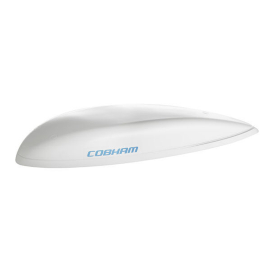
Page 31: Chapter 6 Illustrated Parts List
Chapter 6 Illustrated parts list Figure 6-1: LGA-5005 – HELGA 98-152675-A Cobham Public... -
Page 32: Table 6-1: Legend For Figure Items
Mounting bolts To be supplied by the NAS1101-3-xx installer. Length to be determined by installer Commercially Anti-static cap available Table 6-1: Legend for figure items vv = customer identifier, ccc = minor variant Chapter 6: Illustrated parts list 98-152675-A Cobham Public... -
Page 33: Appendix A Equipment Specifications
1518.0 MHz - 1559.0 MHz Frequency, Transmit Band 1626.5 MHz - 1660.5 MHz and 1668.0 MHz - 1675.0 MHz Software RTCA / DO-178C Level D Hardware RTCA / DO-254 Level D Table A-1: Equipment specifications for LGA-5005 98-152675-A Cobham Public... -
Page 34: Do-160 Specifications
For installation in non-pressurized locations: Max. 55000 ft Overpressure 4.6.3 For installation in pressurized locations: -15000 ft Temperature variation Externally mounted: 10°C/minute Humidity External equipment. Table A-3: Common environmental conditions and tests (DO160G) for LGA-5005 Appendix A: Equipment specifications 98-152675-A Cobham Public... - Page 35 Magnetic Effect 15.0 Magnetic deflection distance: < 0.3 m Power Input 16.0 No power from aircraft. Voltage Spike 17.0 No power from aircraft. Table A-3: Common environmental conditions and tests (DO160G) for LGA-5005 (Continued) 98-152675-A Appendix A: Equipment specifications Cobham Public...
- Page 36 Equipment located outside the pressure vessel, where it will not pose a safety hazard to the aircraft, personnel or equipment in the event of fire. Table A-3: Common environmental conditions and tests (DO160G) for LGA-5005 (Continued) Appendix A: Equipment specifications 98-152675-A Cobham Public...
-
Page 37: Certification
FAA or other certifying agency prior to performing the installation. A.3.2 List of (E)TSOs and deviations This will be added at the time when ETSO and deviations are granted. 98-152675-A Appendix A: Equipment specifications Cobham Public... -
Page 38: Appendix B References
[10] 94-161849, LGA-5005 A350 Floating Mounting Plate, Outline Drawing [11] 98-164146, LGA-5005 A350 Floating Mounting Plate, Installation Notes Manuals and wiring diagrams can be downloaded from www.cobham.com/satcom, Cobham SYNC Partner Portal. Some material and features are for partners only and can only be accessed after login with a password. -
Page 39: Glossary
GLObal’naya NAvigatsionnaya Sputnikovaya Sistema. Global Navigation Satellite System Global Positioning System. HELGA HLD and Enhanced Low Gain Antenna High Power Amplifier, Low Noise Amplifier and Diplexer Low Gain Antenna Low Noise Amplifier. Outline Drawings Original Equipment Manufacturer 98-152675-A Glossary-1 Cobham Public... - Page 40 SDU Configuration Module Satellite Data Unit Supplemental Type Certificate. FAA certification document issued to companies that perform significant modifications on an aircraft. Threaded Neill-Concelman. A type of RF connector used for terminating coaxial cables. Transmitted signal. Glossary-2 98-152675-A Cobham Public...
-
Page 41: Index
, 3-9 mounting holes , 2-4 impedance , 3-9 sealing caps , 4-2 inspection tasks , 3-9 Sealing Kit , 3-1 installation , 4-1, 5-1, 6-1 service , 3-5 installation offset angles , 3-1 shelf life 98-152675-A Index-1 Cobham Public... - Page 42 , 3-1 storage , 3-3 structural loads support , 4-1 contact details , 4-1 contact information , 4-1 technical support , 5-1, 6-1 tools torque , 3-8 mounting bolts , 3-8 TNC connector , 3-1 transportation Index-2 98-152675-A Cobham Public...
- Page 43 98-152675-A www.cobham.com/satcom...
Need help?
Do you have a question about the LGA-5005 HLD and is the answer not in the manual?
Questions and answers