
Related Manuals for Worldcast Systems audemat GOLDENEAGLE ATSC


Summary of Contents for Worldcast Systems audemat GOLDENEAGLE ATSC
- Page 1 GOLDENEAGLE ATSC USER MANUAL (Software version 3.1.x) Date: 2013/05/22 Audemat® is a registered trademark. audemat WorldCast Systems Group web: www.audemat.com - e-mail: contact@audemat.com...
-
Page 2: Table Of Contents
GOLDENEAGLE ATSC v.3.1.x User Manual – 05/2013 CONTENTS 1. INTRODUCTION ............................4 1.1. General information ......................... 4 1.1.1. About Audemat ......................... 4 1.1.2. Regarding ATSC ........................5 1.1.3. Regarding the GOLDENEAGLE ATSC ..................5 1.2. Safety instructions ........................... 7 2. PRODUCT PRESENTATION ........................8 2.1. - Page 3 GOLDENEAGLE ATSC v.3.1.x User Manual – 05/2013 6.6.1. RF Average Measurements ....................56 6.6.2. Mpeg-TS Error ........................56 6.7. System Configuration ........................57 6.7.1. Product ID ..........................57 6.7.2. Date / Time ..........................57 6.7.3. Status ............................58 6.7.4. Users ............................58 6.7.5.
-
Page 4: Introduction
Founded in 1980, Audemat is part of the WorldCast Systems group of companies which combines the collective expertise & extensive product portfolio of several major broadcast brands to offer turnkey systems in all major analog and digital technologies. -
Page 5: Regarding Atsc
GOLDENEAGLE ATSC v.3.1.x User Manual – 05/2013 1.1.2. Regarding ATSC The ATSC Standards document defines a digital television format which replaced (for most consumers in the United States) the analog NTSC television system on June 12, 2009. It was developed by the Advanced Television Systems Committee. - Page 6 GOLDENEAGLE ATSC v.3.1.x User Manual – 05/2013 MPEG2 option: (for RF only version) MPEG monitoring and real time information. Hardware: I/O option: 3 slots are available to add: Metering boards (analog inputs), and/or Status boards (digital inputs) and/or ...
-
Page 7: Safety Instructions
Unplug from mains outlet before any intervention. Any maintenance, adjustment or repair must be carried out by personnel specifically trained by WorldCast Systems. Before switching on the device, make sure the nominal voltage specified on the device matches the mains nominal voltage. -
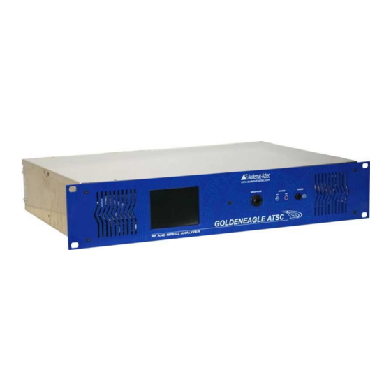
Page 8: Product Presentation
GOLDENEAGLE ATSC v.3.1.x User Manual – 05/2013 2. PRODUCT PRESENTATION 2.1. List of included accessories Check that all these accessories are included: 1 power supply cable, 1 external power supply, 1 Ethernet crossed cable (B), 1 Ethernet straight cable (A), 1 video cable (D), 2 F/BNC cables, 2 F/BNC adapters,... -
Page 9: Front Panel
GOLDENEAGLE ATSC v.3.1.x User Manual – 05/2013 2.3. Front panel Headphone output Status LED Power button and LED Explanation of Leds on front panel: LED RUN: : GOLDENEAGLE ATSC runs normally : GOLDENEAGLE ATSC is off LED HDD: Hard Drive activity LED POWER: : GOLDENEAGLE ATSC is on : GOLDENEAGLE ATSC is off. -
Page 10: Rear Panel
GOLDENEAGLE ATSC v.3.1.x User Manual – 05/2013 2.4. Rear panel Two hardware versions are available. Yours may be fitted with either 1 network connector (version 1) or 2 network connectors (version 2). Version 1 Optional ASI input To power supply transformer Video cable (D) 3 slots available for modular I/O (slots 0, 1 and 2) Loopthrough... -
Page 11: Quick Start For Goldeneagle Atsc
GOLDENEAGLE ATSC v.3.1.x User Manual – 05/2013 3. QUICK START FOR GOLDENEAGLE ATSC 3.1. Network configuration using the front panel application So as to avoid conflict with your network, the IP address for the Navigator DAB/DAB+/T-DMB may be modified right away using the front panel screen. 1. -
Page 12: Connecting To The Embedded Web Site To Install The Applications Of The Goldeneagle Atsc
GOLDENEAGLE ATSC v.3.1.x User Manual – 05/2013 3.3. Connecting to the embedded web site to install the applications of the GOLDENEAGLE ATSC You will now be able to access the embedded web site via Ethernet or Internet to download the remote applications. -
Page 13: Using The Embedded Website
GOLDENEAGLE ATSC v.3.1.x User Manual – 05/2013 4. USING THE EMBEDDED WEBSITE Open a Web browser (Internet Explorer, Mozilla…) and enter the address of the GOLDENEAGLE ATSC. By default: login and password are Admin / admin. The links on the upper left side of the window allow you to access the different web pages used for configuration of the basic GOLDENEAGLE ATSC settings. -
Page 14: Network
GOLDENEAGLE ATSC v.3.1.x User Manual – 05/2013 4.2. Network Definition of the IP configuration: Ethernet configuration mode It is recommended that the user configure the network interfaces with static parameters. Should the unit be set to DHCP, you may lose the ability to access it on the network. -
Page 15: Downloads
GOLDENEAGLE ATSC v.3.1.x User Manual – 05/2013 4.3. Downloads This page will enable you to download the GOLDENEAGLE ATSC application installers GOLDENEAGLE including the ATSC application, ScriptEasy and MasterView. The Management Information Base (MIB) file for accessing the unit using the SNMP protocol is also available on this page. -
Page 16: The Front Panel Application
GOLDENEAGLE ATSC v.3.1.x User Manual – 05/2013 5. THE FRONT PANEL APPLICATION The front panel of the GOLDENEAGLE ATSC is equipped with a touch sensitive color LCD screen. Its application makes it possible to access setup menus, as well as measurements and data analysis. It turns on automatically when the unit is on. -
Page 17: Management
GOLDENEAGLE ATSC v.3.1.x User Manual – 05/2013 5.2. Management Touching the “Management” button will open a menu accessing reboot, shutdown and password reset functions Reboot will restart the equipment, exactly as if the power had been turned off and then back on. Shutdown will terminate the system processes and then turn off the power. -
Page 18: Measure
GOLDENEAGLE ATSC v.3.1.x User Manual – 05/2013 5.5. Measure Touching the Measure button will open the following menu to allow access to measurements and video streaming on the touchscreen. Touch either Frequency or Channel button enter the deisred value, and touch Start, or select the ASI input (if the unit is so equipped). - Page 19 GOLDENEAGLE ATSC v.3.1.x User Manual – 05/2013 Constellation diagram, use for modulation and noise analysis and phase jitter estimation Spectrum display. Used to view shoulder attenuation, frequency response, relative pilot amplitude, and harmonics Eye diagram, to visualize modulation accuracy and jitter Page 19 Head Office : Parc d’activites Kennedy - 20, avenue Neil Armstrong –...
- Page 20 GOLDENEAGLE ATSC v.3.1.x User Manual – 05/2013 Touching the MPEG Info button from the Measure start page opens the MPEG display menu. This menu is only available with the MPEG2 option. MPEG data displays include: MPEG data, including the !st Priority Transport stream errors PID/PSIP list and bit rates.
-
Page 21: Video
GOLDENEAGLE ATSC v.3.1.x User Manual – 05/2013 5.5.1. Video Touching the Video button will display the video stream from the selected multiplex. The buttons at the bottom of the screen will allow selection of the various streams within the configured signal. -
Page 22: The Remote Application
GOLDENEAGLE ATSC v.3.1.x User Manual – 05/2013 6. THE REMOTE APPLICATION 6.1. Launching the GOLDENEAGLE ATSC application All of the monitoring setup, readings, real-time measurements and configuration for the GOLDENEAGLE ATSC are accomplished by using a remote application. This software is stored in the GOLDENEAGLE and is available for downloading from the embedded web site on the “Download"... - Page 23 GOLDENEAGLE ATSC v.3.1.x User Manual – 05/2013 The initial view presented by the application depends on the configuration. After initial setup, when stations are configured for monitoring, the software will open on the Status page, which will be covered in a later section.
-
Page 24: Setting Preferences
GOLDENEAGLE ATSC v.3.1.x User Manual – 05/2013 6.2. Setting preferences Display the options using the FileOptions menu to set application parameters. Set the path for vlc.exe, the VLC media player. Version 1.0.0 or newer is necessary to stream videos. ... -
Page 25: Monitoring Configuration
GOLDENEAGLE ATSC v.3.1.x User Manual – 05/2013 6.3. Monitoring configuration 6.3.1. Creating a new channel After clicking on the “Monitoring” button, the “New channel” button is available in the left panel. Click on it: Click on the “Start" button in order to discover and display the ATSC signals present in the TV band The software will display a scan of the television band (VHF and UHF), with red bars indicating all of the... -
Page 26: Rf / Mpeg
GOLDENEAGLE ATSC v.3.1.x User Manual – 05/2013 6.3.2. RF / MPEG Click on the “RF / MPEG button”, the list of configured channels appears in the lower left part of the application. Click on any multiplex to select it, you will then be able to configure alarms, thresholds and other parameters in the main window of the application by selecting from the following tabs: ... - Page 27 GOLDENEAGLE ATSC v.3.1.x User Manual – 05/2013 6.3.2.1 Basic Information tab Muliplex Information: Multiplex name, channel number and frequency are set automatically. The Multiplex name can be modified, and optional Transmitter and Netowrk names can be entered. The “Monitoring " field enables monitoring of this channel to be activated or put on stand-by.
- Page 28 GOLDENEAGLE ATSC v.3.1.x User Manual – 05/2013 6.3.2.2 RF level There are three thresholds, any or all of which can be configured to send an alarm: high level, low level 1, low level 2. These levels can be adjusted in two different ways: ...
- Page 29 GOLDENEAGLE ATSC v.3.1.x User Manual – 05/2013 Explanation of thresholds and hysteresis: Triggering and end of a high threshold alarm 1st overshoot 5th overshoot high threshold time window time window time window less than 4 overshoots: more than 4 overshoots: less than 4 overshoots: no alarm alarm is sent...
- Page 30 GOLDENEAGLE ATSC v.3.1.x User Manual – 05/2013 6.3.2.3 Pilot level The user can configure two alarm triggering thresholds: high level low level These levels can be adjusted in the same ways as the RF level thresholds: Page 30 Head Office : Parc d’activites Kennedy - 20, avenue Neil Armstrong –...
- Page 31 GOLDENEAGLE ATSC v.3.1.x User Manual – 05/2013 6.3.2.4 MER level Configure low level alarm triggering threshold. This level can be adjusted in the same ways as the RF and Pilot level settings. Settings for hysteresis and delay before alarm are also available. NOTE: MER levels are given as an absolute value.
- Page 32 GOLDENEAGLE ATSC v.3.1.x User Manual – 05/2013 6.3.2.5 Error Rate This function allows monitoring BER before and after FEC (forward error correction). The value of the BER “Trigger" is a multiple of 10 2 . 10 . Ex: 200 . 10 The “Disappearance"...
- Page 33 GOLDENEAGLE ATSC v.3.1.x User Manual – 05/2013 6.3.2.6 First Priority This page is only available with the MPEG2 option. This page is to configure monitoring of first priority transport stream errors – TS Sync loss, Sync byte error, PAT error, Continuity count error, PMT error, and PID error, Put a check in each box on the left side for which monitoring is desired.
- Page 34 GOLDENEAGLE ATSC v.3.1.x User Manual – 05/2013 6.3.2.7 Second & Third Priority This page is only available with the MPEG2 option. This page is to configure monitoring of second and third priority transport stream errors – Transport errors, CRC errors, PTS errors, CAT errors and unreferenced PID errors Put a check in each box on the left side for which monitoring is desired.
- Page 35 GOLDENEAGLE ATSC v.3.1.x User Manual – 05/2013 6.3.2.8 PSIP This page is only available with the MPEG2 option. This page is to configure monitoring of PSIP (Program Service and Information Protocol) errors – MGT error, TVCT error, RRT error, EIT errors, ETT errors, and STT error. Put a check in each box on the left side for which monitoring is desired.
- Page 36 GOLDENEAGLE ATSC v.3.1.x User Manual – 05/2013 6.3.2.9 Alarm hierarchy RF < low2 Pilot < low RF < low1 Receiver Lock TS Synchro MER<low Pilot > high RF > high First Priority Second Priority Third Priority PSIP Error The hierarchy is a ranking of alarms in terms of importance. Lesser alarms will be closed if and when a higher priority alarm occurs.
-
Page 37: Mpeg (For Units With The Asi Input Enabled)
GOLDENEAGLE ATSC v.3.1.x User Manual – 05/2013 6.3.3. MPEG (for units with the ASI input enabled) For GOLDENEAGLE ATSC units that have the ASI monitoring input enabled, an additional menu choice will appear just below the RF/MPEG button: This page allows the user to configure the monitoring of the MPEG data on the ASI input. If the unit has the ASI input enabled, the input will automatically be monitored and appear in the Status page. -
Page 38: Monitoring Scan
GOLDENEAGLE ATSC v.3.1.x User Manual – 05/2013 6.3.4. Monitoring scan The GOLDENEAGLE ATSC creates a scan of the entire band during the channel creation process. Using the settings on this page, the user can configure the unit to repeat the scan on a regular basis and, if desired, send alarms when differences between the two scans are detected. - Page 39 GOLDENEAGLE ATSC v.3.1.x User Manual – 05/2013 Scan configuration Display Scan Bar Select the bargraph(s) you want to display: Maximum scan Reference scan Current scan Minimum scan A zoom function is available to accommodate the potentially large number of channels.To activate it, select the area to vizualise (click and drag with the mouse);...
- Page 40 GOLDENEAGLE ATSC v.3.1.x User Manual – 05/2013 Scan Monitoring Management From here, you will be able to: Enable scan monitoring (single event if an alarm has not been activated). Activate the channel appearance alarm. Activate the channel disappearance alarm. Enable the sending of alarms on changes in channel strength (triggering differences) Set the offset value that will trigger the level difference alarm (+/- this value in dB compared with the reference level).
-
Page 41: Records
GOLDENEAGLE ATSC v.3.1.x User Manual – 05/2013 6.3.5. Records This menu allows the user to schedule the GOLDENEAGLE ATSC to record video and audio from any receivable multiplex, or to initiate an immediate (manual) recording, The following functions are available: ... - Page 42 GOLDENEAGLE ATSC v.3.1.x User Manual – 05/2013 Downloading Recordings Video/picture/text recordings can be downloaded onto a computer by using any FTP client (File Transfer Protocol), you may use FILEZILLA, available on the Audemat CD. Login with the FTP software using the following information: ...
-
Page 43: Mpeg Settings
GOLDENEAGLE ATSC v.3.1.x User Manual – 05/2013 6.3.6. MPEG Settings The settings on this page allow the user to configure timeout delays for each of the MPEG parameters being monitored. The default values are set according to the ATSC standard, and it is not recommended that the user make any changes. -
Page 44: Status
GOLDENEAGLE ATSC v.3.1.x User Manual – 05/2013 6.4. Status 6.4.1. Snapshot The status of each monitored channel is displayed, with simulated LEDs to indicate alarms or error conditions. The status of the video streams on the ASI input is displayed in a similar fashion on units that are so equipped. - Page 45 GOLDENEAGLE ATSC v.3.1.x User Manual – 05/2013 The screen is divided in two parts: On the left side: For each multiplex (and the ASI input, if so equipped), a list of parameters with their status is available. To expand the list to display all parameters for one or several channels, click the plus sign (+) next to the muliplex number.
- Page 46 GOLDENEAGLE ATSC v.3.1.x User Manual – 05/2013 On the right side: The user will find a snapshot of each available video channel in each multiplex. These snapshots are updated every few seconds, depending on the number of multiplexes being monitored. If the unit is equipped for the ASI input, the snapshots for videos in the ASI transport stream will appear along with the pictures from the RF multiplexes.
- Page 47 GOLDENEAGLE ATSC v.3.1.x User Manual – 05/2013 Notes: 1- If the channel is scrambled, the following screen is displayed: 2- If the capture is not possible, the following screen is displayed. This also could indicate a problem with the RF feed to the streaming Tuner.
-
Page 48: Event Log
GOLDENEAGLE ATSC v.3.1.x User Manual – 05/2013 6.4.2. Event log This tab displays a history of the alarms, with details. The “Search History Log" function enables the user to filter the events he wants to display by date, source of the event, or even the specific type of event (see example below). Page 48 Head Office : Parc d’activites Kennedy - 20, avenue Neil Armstrong –... -
Page 49: Realtime
GOLDENEAGLE ATSC v.3.1.x User Manual – 05/2013 6.5. Realtime Note: All "real time" functions will suspend monitoring of the configured multiplexes! For this reason, any real time measurement will stop automatically after 4 hours, allowing the unit to resume it’s normal monitoring functions. - Page 50 GOLDENEAGLE ATSC v.3.1.x User Manual – 05/2013 Mer, preBer, postBer. Each may be checked or unchecked depending on what the user wants to display. Note that pre and post BER measurements will not display until there are errors detected. In addition, using the buttons in the Graph Selector panel on the right, you may select other types of displays: ...
- Page 51 GOLDENEAGLE ATSC v.3.1.x User Manual – 05/2013 Spectrum: Used to visualize shoulder attenuation, amplitude frequency response, Pilot carrier amplitude, harmonics. Page 51 Head Office : Parc d’activites Kennedy - 20, avenue Neil Armstrong – 33700 Bordeaux-Merignac (France) Tel +33 (0)5 57 928 928 – Fax +33 (0)5 57 928 929 – –...
-
Page 52: Mpeg Realtime
GOLDENEAGLE ATSC v.3.1.x User Manual – 05/2013 6.5.2. Mpeg Realtime These pages are only available with the MPEG2 option. 6.5.2.1 Mpeg data As with RF measurements, select one of the monitored channels, enter a frequency/channel number or select the ASI input (if equipped) and click the green start arrow. -
Page 53: Mpeg Error
GOLDENEAGLE ATSC v.3.1.x User Manual – 05/2013 6.5.2.2 Mpeg error Select a channel (or the ASI input if available) and begin the measurement. The readings will begin to display in strip chart style, from right to left. The software will display a red dot on the moving timeline for each second in which that referenced error occurs. -
Page 54: Video Streaming
GOLDENEAGLE ATSC v.3.1.x User Manual – 05/2013 6.5.3. Video Streaming Note: before streaming, you’ll need to install VLC media player and set the path to the application in the File/Option menu of the GOLDENEAGLE ATSC software. VLC media player 1.0.0 or later is necessary to stream the video and audio from the GOLDENEAGLE ATSC. - Page 55 GOLDENEAGLE ATSC v.3.1.x User Manual – 05/2013 High quality streaming Mosaic for all channels of a selected multiplex Three quality levels are available, to accommodate different network bandwidths: High Slide show: recommended if the bandwidth is low, show about 2 slides per second (depending on the available bandwidth).
-
Page 56: Measurements
GOLDENEAGLE ATSC v.3.1.x User Manual – 05/2013 6.6. Measurements 6.6.1. RF Average Measurements This page dispays the average recorded measurements for all of the channels configured in the monitoring list (see ‘Config’). Select the desired channel in the drop-down menu and click the green start arrow to display the readings. -
Page 57: System Configuration
GOLDENEAGLE ATSC v.3.1.x User Manual – 05/2013 6.7. System Configuration Clicking on the System Configuration button will open a new window where the user may configure system parameters. NOTE: When any changes are made, the user must click on the ‘Update’ button to save the changes! 6.7.1. -
Page 58: Status
GOLDENEAGLE ATSC v.3.1.x User Manual – 05/2013 6.7.3. Status This page displays information about the operational status of the hardware. It is also possible to configure thresholds for certain operating parameters that will trigger an alarm to be sent to technical personnel. -
Page 59: Network
GOLDENEAGLE ATSC v.3.1.x User Manual – 05/2013 6.7.5. Network This System Configuration page enables the user to view and change the parameters of the GOLDENEAGLE ATSC network interface. The unit may be configured with static IP settings, or can obtain network parameters from a DHCP server. The bottom of the page displays the current network status, including information on the PPP settings. -
Page 60: Ppp Dial-Out
GOLDENEAGLE ATSC v.3.1.x User Manual – 05/2013 6.7.6. PPP Dial-Out The GOLDENEAGLE ATSC can use an optional modem to create a Point to Point Protocol (PPP) network connection over a regular dial up phone line, for connectivity at sites without a regular Ethernet network. -
Page 61: Ppp Dial-In
GOLDENEAGLE ATSC v.3.1.x User Manual – 05/2013 6.7.7. PPP Dial-In As with PPP Dial-Out, the GOLDENEAGLE ATSC can be configured to accept incoming PPP connections on the (optional) modem. All of the necessary settings for hosting such connections are available on this page of the System Configuration window. Page 61 Head Office : Parc d’activites Kennedy - 20, avenue Neil Armstrong –... -
Page 62: Phone Alerts
GOLDENEAGLE ATSC v.3.1.x User Manual – 05/2013 6.7.8. Phone Alerts This optional feature comes with a USB modem, and allows the GOLDENEAGLE ATSC to call out to technical personnel on alarm conditions. The user can configure an access code that will be used to acknowledge the alarm when the unit calls in order to, and lists of phone numbers for the unit to dial. -
Page 63: Smtp Mail Client
GOLDENEAGLE ATSC v.3.1.x User Manual – 05/2013 6.7.9. SMTP Mail Client One of the primary methods of alarm notifications is SMTP, otherwise known as e-mail. This page contains all the settings to connect the GOLDENEAGLE ATSC to an SMTP server – server address, login information, and up to 3 destination addresses. -
Page 64: Snmp Agent
GOLDENEAGLE ATSC v.3.1.x User Manual – 05/2013 6.7.10. SNMP Agent SNMP, the Simple Network Management Protocol, is the other primary form of notification used by the GOLDENEAGLE ATSC to send alarm notifications. The messages, called ‘traps’ can be sent to up to four network manager computers. -
Page 65: I/O Layout
GOLDENEAGLE ATSC v.3.1.x User Manual – 05/2013 NOTE: only the main manager computer (the first IP address in the SNMP page) has the authority to acknowledge SNMP alarm traps! 6.7.12. I/O Layout The GOLDENEAGLE ATSC, as an option, can host up to three input/output cards to enable control and monitoring capabilities at the remote site. -
Page 66: Webcam
GOLDENEAGLE ATSC v.3.1.x User Manual – 05/2013 6.7.15. Webcam The GOLDENEAGLE ATSC can also support a USB webcam. NOTE: Not all webcams will work, since this is not a Windows or Mac operating system. In order to assure proper webcam function, the webcam must be purchased through Audemat. The settings on this page allow the user to check for webcam availability (might require a reboot), and to enable webcam functions. -
Page 67: Support
GOLDENEAGLE ATSC v.3.1.x User Manual – 05/2013 6.7.17. Support The functions of this page in System Configuration deal with internal operations of the GOLDENEAGLE.The user may restart the operating system (embedded software) of the unit, reboot the GOLDENEAGLE, or shut down the unit completely. NOTE: The unit cannot be restarted remotely, the power switch on the front panel must be used. -
Page 68: About
GOLDENEAGLE ATSC v.3.1.x User Manual – 05/2013 6.8. About The "About" menu of the application displays the equipment configuration on the Summary tab: On the Licenses tab, optional license information is displayed, this is also where you can install new license keys (see next section). -
Page 69: Installing Software Options
GOLDENEAGLE ATSC v.3.1.x User Manual – 05/2013 7. INSTALLING SOFTWARE OPTIONS Contact your sales representative in order to obtain the software key that will allow you to activate the MPEG2 option, Phone Alerts, the ASI input, etc. Then, follow the procedure. Upgrade process 1. -
Page 70: Optional Input / Output Configuration
GOLDENEAGLE ATSC v.3.1.x User Manual – 05/2013 8. OPTIONAL INPUT / OUTPUT CONFIGURATION 8.1. Status board / Digital inputs Please refer to the ScriptEasy manual for more information on I/O management. This module provides 16 digital inputs and can work in 2 different modes depending on jumper configuration: Schematic diagram: ... - Page 71 GOLDENEAGLE ATSC v.3.1.x User Manual – 05/2013 ‘External power supply’ mode: Install one jumper only in the middle of the pins. 1 jumper in the middle Digital input module external connection diagram: External connections on SUB-D 25pts female connector located at the end of the board. PIN NUMBER DESCRIPTION SUB-D 25pts FEMALE CONNECTOR...
-
Page 72: Command Board / Relay Outputs
GOLDENEAGLE ATSC v.3.1.x User Manual – 05/2013 8.2. Command board / Relay outputs Please refer to the ScriptEasy manual for more information on I/O management. This module provides 8 bistable relays. Each relay has one com input (common) and two outputs: NC (normally closed) and NO (normally opened). - Page 73 GOLDENEAGLE ATSC v.3.1.x User Manual – 05/2013 Relay output module external connection diagram: External connections on SUB-D 25pts male connector located at the end of the board. Each circuit can support 5A between -60 V and +60 V. A +12 V power supply with a max current of 250 mA is available on pin 13.
-
Page 74: Metering Board / Analog Inputs
GOLDENEAGLE ATSC v.3.1.x User Manual – 05/2013 8.3. Metering board / Analog inputs Please refer to the ScriptEasy manual for more information on I/O management. This module provides 8 analog inputs designed to measure voltages up to 50 V. It is possible to select the measurement range for a better accuracy while converting. -
Page 75: Appendix A: Glossary
GOLDENEAGLE ATSC v.3.1.x User Manual – 05/2013 APPENDIX A: GLOSSARY AC-3: Audio code using the AC-3 Dolby method ADSL - Asymmetric Digital Subscriber Line AGC - Automatic Gain Control ASI - Asynchronous Serial Interface ATSC - Advanced Television Standard Committee ATSC - Australian Telecommunication Standardization Committee BER - Bit Error Rate or Bit Error Ratio BIT: 'binary digit' –... - Page 76 GOLDENEAGLE ATSC v.3.1.x User Manual – 05/2013 OFDM - Orthogonal Frequency Division Multiplexing PAP - Password Authentication Protocol PER - Packet Error Ratio PES - Packetized Elementary Stream (sometimes called Program Elementary Stream) PID - Packet Identifier POP3 - Post Office Protocol 3 PPP - Point-to-Point Protocol PS - Program Stream PSK - Phase Shift Keying...
-
Page 77: Appendix B: For Further Information
FRANCE Tel: +33 (0) 557 928 928 | Fax: +33 (0) 557 928 929 Hotline: support@audemat.com WorldCast Systems Inc 19595 NE 10 Ave, Suite A Miami FL 33179 Tel: +1 (305) 249 31 10 | Fax: +1 (305) 249 31 13 Page 77 Head Office : Parc d’activites Kennedy - 20, avenue Neil Armstrong –...
Need help?
Do you have a question about the audemat GOLDENEAGLE ATSC and is the answer not in the manual?
Questions and answers