
Related Manuals for Japan Radio Co. JLR-8400


Summary of Contents for Japan Radio Co. JLR-8400
- Page 1 JLR - 8400 8400 GPS NAVIGATOR GPS NAVIGATOR INSTRUCTION INSTRUCTION MANUAL MANUAL...
- Page 3 Safety Cautions Cautions for High Voltage High voltage of hundreds volts is used inside this equipment. Touching a component inside the unit is very dangerous. Any person other than specialized maintenance staffs should not maintain, inspect, or adjust the unit. High voltages on the order of tens of thousand volts are most likely to cause instant deaths from electrical shocks.
-
Page 4: Emergency Measures
● Emergency Measures ● Method of First-Aid Treatment Precautions for First-Aid Treatments Apply artificial respiration to the person who collapsed, minimizing moving as much as possible avoiding risks. Once started, artificial respiration should be continued rhythmically. (1) Refrain from touching the patient carelessly as a result of the accident; the first-aider could suffer from electrical shocks by himself or herself. - Page 5 ☆Treatment to Give When the Patient Has a Pulse Beating but Has Ceased to Breathe ∗ Performing mouth-to-mouth artificial respiration Bend the patient's face backward until it is directed to look back. (A pillow may be placed under the neck.) Pull up the lower jaw to open up the airway.
- Page 6 Flow of Cardiopulmonary Resuscitation (CPR) A person is collapsing. A person is collapsing. - Secure the safety of the surrounding area. - Secure the safety of the surrounding area. - Prevent secondary disasters. - Prevent secondary disasters. Listen to the appeal of the Responding Check for response.
- Page 7 Specific Procedures for Cardiopulmonary Resuscitation (CPR) 1. Check the scene for safety to prevent secondary disasters a) Do not touch the injured or ill person in panic when an accident has occurred. (Doing so may cause electric shock to the first-aiders.) b) Do not panic and be sure to turn off the power.
- Page 8 b) If the injured or ill person is breathing, place him/her in the recovery position and wait for the arrival of the emergency services. • Position the injured or ill person on his/her side, maintain a clear and open airway by pushing the head backward while positioning their mouth downward.
- Page 9 2) Perform chest compressions Compress • Perform uninterrupted chest compressions of 30 with these at the rate of about 100 times per minute. parts (the heels of While locking your elbows positioning yourself both vertically above your hands. hands). • With each compression, depress the chest wall to a depth of approximately 4 to 5 cm.
- Page 10 11. Attach the electrode pads to the injured or ill person's bare chest a) Remove all clothing from the chest, abdomen, and arms. b) Open the package of electrode pads, peel the pads off and securely place them on the chest of the injured or ill person, with the adhesive side facing the chest.
- Page 11 15. Automatic electrocardiogram analysis a) When 2 minutes have elapsed since you resumed cardiopulmonary resuscitation (CPR), the AED automatically analyzes the electrocardiogram. b) If you suspended CPR by following voice prompts and AED voice prompt informs you that shock is needed, give electric shock again by following the voice prompts. If AED voice prompt informs you that no shock is needed, immediately resume CPR.
-
Page 12: Foreword
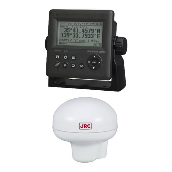
Foreword Thank you for purchasing the JRC GPS Navigator JLR-8400. This equipment is a high-performance navigation equipment consisting of a GPS sensor and navigator, can retrieve the position data using the GPS sensor to display various navigation information on the display. -
Page 13: Before Commencing The Operation
Before Commencing the Operation Symbols Several symbols are used in this manual to ensure safety and proper operation of the equipment and to avoid possible human injury or property damage. These symbols and their meanings are shown below. Please read and understand these symbols before proceeding to read this manual. -
Page 14: Precautions Upon The Operation
Precautions Upon the Operation WARNING Do not disassemble or modify the equipment. Doing so may result in fire, electric shock, or equipment failure. Do not allow the display to become wet. Doing so may result in fire, electric shock, or equipment failure. Operate the equipment only at the indicated voltage. - Page 15 Precautions Upon the Operation CAUTION Do not use the equipment in the environment other than those provided in the specification. Doing so may result in equipment failure, malfunction, or injury. Do not install the equipment in the place subject to vibration or shock. Doing so may result in the equipment falling or collapsing, resulting in equipment failure or injury.
- Page 16 CAUTION When connecting the cable attached to the equipment, do not bend it acutely, twist it, or impart excessive force. Doing so sometimes causes cracks or damage to the coating, resulting in fire or electrocution. Do not install the sensor where there is excessive vibration. Vibration may cause sensor failure.
-
Page 17: Appearance Of The Equipment
Appearance of the Equipment ●NWZ-4620 Display Unit ●JLR-4350 GPS Sensor Unit... -
Page 18: Terminology
Terminology Term Meaning (Descriptions) 2D (2 dimension) Positioning with antenna elevation height in addition to satellite data. 3D (3 dimension) The three dimensional position fix, 4 or more satellites required. Active route Route that is currently used by a ship Anchor alert This alert monitors that the own ship is the preset distance or more away from the waypoint. - Page 19 Log Pulse Contact output signal, output pulse per nm. Expressed in units of "p/nm". mi/h Unit of ship speed. Loran time difference display Method for expressing the present position with loran system time difference. (The method is for operators who have a background in loran navigation.) Multi GNSS Positioning using multiple satellite systems at the same time.
-
Page 20: Table Of Contents
Contents ● SAFETY CAUTIONS ● ........................I ● EMERGENCY MEASURES ● ......................II FOREWORD ............................X BEFORE COMMENCING THE OPERATION ..................XI PRECAUTIONS UPON THE OPERATION ..................XII PRECAUTIONS UPON THE OPERATION ..................XIII APPEARANCE OF THE EQUIPMENT ....................XV TERMINOLOGY ..........................XVI SECTION 1 EQUIPMENT OVERVIEW ................ - Page 21 4.4.2.1 Registering the Own Ship Position ................. 4-20 4.4.2.2 Registering Latitude and Longitude ............... 4-20 4.4.2.3 Registering a Bearing and Distance from a Specified Position ......4-21 4.4.3 Editing Waypoint Information ..................4-22 4.4.4 Copying Waypoint Information ..................4-23 4.4.5 Deleting Waypoints ......................
- Page 22 4.13.5 Setting Position, Speed, and Course Smoothing ............4-59 4.13.6 Setting RAIM ........................4-59 4.13.7 Initializing the GPS ......................4-60 4.13.8 Setting Beacon ....................... 4-61 4.13.9 Setting SBAS ......................... 4-62 4.13.10 Setting multi GNSS ......................4-63 4.14 BEACON INFORMATION ....................4-64 4.15 EQUIPMENT CONFIGURATION ..................
- Page 23 6.4.3 SENSOR/DATA2 Connector ..................6-23 OPTIONAL PERIPHERAL CONNECTION ................. 6-25 6.5.1 Sub-Display Connection ....................6-25 6.5.2 Printer Connection ......................6-25 6.5.3 Dimmer Unit Connection ....................6-26 6.5.4 Junction Box Connection ....................6-27 6.5.5 Coaxial Cable Kit Connection ..................6-29 6.5.6 Output buffer (NQA-4351) ....................
-
Page 25: Equipment Overview
Section 1 Equipment Overview 1.1 Functions This equipment (JLR-8400) is a GPS navigator with a JLR-4350 GPS sensor being connected to the NWZ-4620 display unit. The GPS navigator operates around-the-clock to measure the position with high accuracy anywhere in the world and in all weather conditions by using the GPS satellites. In addition, the GPS navigator can increase the accuracy of position fixing by receiving correction data from the SBAS satellites. -
Page 26: Configuration
1.3 Configuration 1.3.1 Standard configuration JLR-8400 Name Model Code Q'ty Note Display Unit NWZ-4620 NWZ-4620 Main body 14 cores/2 m/with Fuse Data Power Cable CFQ-5766A CFQ5766A holder data/contact/power Fuse MF60NR 250V 1 5ZFGD00205 Display unit 1A fuse Front Panel MTV305018A... - Page 27 1.3.2 Option Name Model Code Q'ty Note For InmarsatC AC/DC Power AC100/220V, DC24V NBD-904 NBD904 supply unit Input DC24V Output 14 cores/10 m/ CFQ-5766D CFQ5766D With Fuse holder data/contact/power Data Power Cable 14 cores/20 m/ CFQ-5766F CFQ5766F With Fuse holder data/contact/power Data Cable CFQ-5769...
-
Page 28: Construction
1.4 Construction NWZ-4620 Display Unit NWZ-4620 Desktop type Unit: mm Mass: Approximately 0.8 kg... - Page 29 JLR-4350 GPS Sensor Unit Unit: mm Mass: Approximately 1.2kg (include 15m cable) Color: Munsell N9 IP Grade: IP56 (IEC60945) NBD-904 AC/DC Power supply unit Serial Number Seal Volume x 3 Mounting Holes Fuse x 2 4-dia6x8 Unit: mm Mass:Approximately 2.6 kg...
- Page 30 NQE-7700A Junction Box DGPS Cable CFQ-8919 Gland 15 Cable diameter 5 - 11 Gland 25 Cable diameter 10 - 20 Unit: mm Mass: Approximately 0.6 kg...
- Page 31 NQD-4414 Coaxial Cable Kit (outdoor use: NQD-4410) (Installation Screw M8) Unit: mm Mass: Approximately 1.5 kg NQD-4414 Coaxial Cable Kit (indoor use: NQD-4411) (Installation Screw M3) Unit: mm Mass: Approximately 0.7 kg...
- Page 32 NQA-4351 Output Buffer Unit: mm Mass: Approximately 0.8 kg...
- Page 33 NCZ-777 Select Switch (Stationary) (Installation Screw M6) Unit: mm Mass: Approximately 0.5 kg NCZ-777 Select Switch (Flush Mounting) (Installation Screw M6) Unit: mm Mass: Approximately 0.7 kg...
- Page 34 NCZ-1663 Select Switch (Stationary) Unit: mm Mass: Approximately 0.2 kg 1-10...
- Page 35 NCZ-1663 Select Switch (Flush Mounting) Unit: mm Mass: Approximately 0.2 kg 1-11...
- Page 36 NCZ-1537B Select Switch (Flush Mounting) Unit: mm Mass: Approximately 0.55 kg 1-12...
- Page 37 CQD-10 Junction Box 4-φ7.5 (Installation Screw M6) Unit: mm Mass: Approximately 1.1 kg 1-13...
- Page 38 NKG-104 Printer Unit: mm Mass: Approximately 2.1 kg 1-14...
-
Page 39: System Diagram
1.5 System Diagram JLR-4350 GPS Sensor NQE-7700A Junction Box 250V-MPYCYS-7 Extension Cable T-shaped Connector SENSOR/DATA2 AA-040404-MMM-TL RS-485 DATA1 CFQ-5769 NWZ-4620 Display Contact External Dimmer/ACK DC12/24V DATA *250V-TTYCS-1 Contact External Buzzer/Log Pulse CFQ-5766A *250V-TTYCS-1 Junction Data Power Cable (2 m) CQD-10 Radar Serial ECDIS/Plotter... - Page 40 1-16...
-
Page 41: Names And Functions Of The Components
Section 2 Names and Functions of the Components 2.1 NWZ-4620 DISPLAY UNIT Unit (Front) Display Information received from the GPS sensor, the equipment setting screen, etc. are displayed. Speaker Operation panel Operation panel Operation Name Functions panel Power/ Use this key to turn on the power. Adjust the Contrast key contrast. - Page 42 Reading the Display ● RAIM Accuracy level Display the preset accuracy level In operation: 10m/30m/50m/100m RAIM OFF: "-" Date Time U: UTC time SAFE:No faulty satellite L: Local time CAUTION:RAIM impossible UNSAFE:Presence of fault satellite Display area Freeze indicator During operation, the black Status bar part moves.
-
Page 43: Jlr-4350 Gps Sensor
2.2 JLR-4350 GPS Sensor Radome 6 pins Connector Approx. φ19mm Base Mounting Screw 1 inch 14 UNS-2B Data Cable 15m Approx. φ6mm... -
Page 45: Display Screen
GNSS Satellite elevation to scroll the screen. GNSS Satellite signal level 45 to 55 normal condition ※JLR-8400 does not support neighboring beacon station information. 4) Beacon information (Type 16 massage) screen The beacon information screen displays message type16 information. Massage area... - Page 46 5) CDI screen Deviation from the route Deviation from the route is displayed. BRG and DTG can be displayed by pressing Steering direction Waypoint number Waypoint Own ship's position "-": less than 1 knot Width of the route 6) Distance (Trip) screen Trip is displayed.
- Page 47 9) Neighboring beacon station information screen The neighboring beacon station information screen can display the Station number, name, frequency and bitrate. JLR-8400 does not support this screen. 10) Waypoint Information screen The waypoint screen can display the waypoint number, route number and waypoint position.
-
Page 49: Operation
Section 4 Operation 4.1 Menu List Main Menu Sub Menu Range Note CONTRAST 1-13 4.9.1 DIMMER MAXIMUM 4-13 4.9.2 DIMMER TYPICAL 3-12 4.9.2 DIMMER MINIMUM 2-11 4.9.2 CLICK SOUND ON/OFF 4.9.3 DISPLAY DISPLAY SELECTION 4.9.4 DISPLAY1 4.9.4.1 SEGMENTATION1 4.9.4.2 DISPLAY 4.9.4.2 OWN SHIP POS※1/COG/SOG... - Page 50 Main Menu Sub Menu Range Note DISPLAY2 Same as DISPLAY 1 4.9.4.1 DISPLAY3 Same as DISPLAY 1 4.9.4.1 DISPLAY4 Same as DISPLAY 1 4.9.4.1 DISPLAY5 Same as DISPLAY 1 4.9.4.1 DISPLAY6 Same as DISPLAY 1 4.9.4.1 BACK LIGHT WHITE/ORANGE 4.9.5 WAYPOINT MARK ○...
- Page 51 Main Menu Sub Menu Range Note UNIT 4.10.1 DIST/SPD NM,kn / km,km/h / mi.mi/h / m,m/s 4.10.1 ANT HEIGHT m / ft / fm 4.10.1 TIME DIFF -13:00 - +13:30 4.10.2 ‘YY-MMM-DD HH:MM/ DATE DISP DD MMM,'YY HH:MM/ 4.10.3 MMM DD,'YY HH:MM SYSTEM MAG CORR 4.10.4...
- Page 52 STATION ADD※2 4.13.8 STATION DELETE※2 4.13.8 SBAS 4.13.9 SBAS SEARCH AUTO/ MANUAL Selection 4.13.9 TYPE 0 INFO ON/OFF 4.13.9 MULTI GNSS 4.13.10 QZSS ON/OFF 4.13.10 GLONASS ON/OFF 4.13.10 ON/OFF 4.13.10 BEACON DISPLAY ON/OFF 4.14 ※2 JLR-8400 does not support this function.
- Page 53 Main Menu Sub Menu Range Reference/Note DATA I/O 4.15.4 DATA IN/OUT1 NMEA/JRC/IEC 4.15.4 NMEA 4.15.4 DATA IN/OUT SEND/RECEIVE 4.15.4 VERSION 1.5/21./2.3/4.0 4.15.4 SEND Only SENTENCE SENTENCE LIST 4.15.4 SEND Only BIT RATE 4800/9600/19200/38400 4.15.4 TALKER SELECT RECEIVED/FIXED GP 4.15.4 4.15.4 INTERVAL OFF/4s 4.15.4...
- Page 54 Main Menu Sub Menu Range Reference/Note RS-485 NMEA/IEC 4.15.3 NMEA 4.15.3 VERSION 1.5/21./2.3/4.0 4.15.3 SENTENCE SENTENCE LIST 4.15.3 BIT RATE 38400/57600/76800/115200 4.15.3 TAKER SELECT RECEIVED/FIXED GP 4.15.3 4.15.3 SENTENCE SENTENCE LIST 4.15.3 INTERFACE BIT RATE 38400/57600/76800/115200 4.15.3 TAKER SELECT RECEIVED/FIXED GP 4.15.3 CONTACT INPUT DIMMER/ACK...
-
Page 55: Basic Operation
4.2 Basic Operation 4.2.1 Turning the Unit On When the main power is turned on, the power to the display unit is automatically turned on. In the state in which the power is turned off by the display unit key operation, pressing the turns on the power. - Page 56 1. A receiver is selected. Select the receiver connected. 1.RECEIVER SELECT : JLR-4350▼ When JLR-4341/4340/4350/4351 are selected by mistake, turn OFF a power immediately and carry out action 1. When selected except JLR-4341/4340/4350/4351 by mistake, turn OFF a power and carry out power ON again.
-
Page 57: Startup (Standard)
4.2.1.1 Startup (Standard) If all the self-check results are ‘OK’, the screen is automatically changed to the normal screen. 4.2.1.2 Startup (Error-1) If the self-diagnosis results are errors “NG,” the results are displayed as follows. WARNING V ROM [2] Supplement When any abnormality (NG) is found, contact JRC or one of our agents. -
Page 58: Turning Off The Power
4.2.2 Turning off the power If the key and the key are pressed and held down simultaneously, the power will be turned off and the screen display will turn off. Supplement The power may be turned on due to the release timing of your finger. In this case, first release the and then release the 4.2.3... -
Page 59: Turning Off The Buzzer
4.2.7 Alert display CAUTION JLR-8400 indicates alerts by text box instead of color alert icons because it adopts monochrome display. When an alert occurs, the event is notified with a popup menu and alert sound. W A R N I N G V G P S ... -
Page 60: Selecting Items From The Menus
4.2.8 Selecting items from the menus This section shows the procedure for selecting items from the menus and determining the selection. Procedure Press Move the cursor to a required item by using and press . The item is selected and a submenu is opened to enable selection of details. -
Page 61: Entering A Numeric Value
4.2.9 Entering a numeric value This section describes the procedure for entering a numeric value. Procedure Move the cursor to the field in which a value is to be entered by using Set a numeric value to be entered by using and press Move the cursor to the right most field and press . -
Page 62: Plot Screen Operation
4.3 Plot Screen Operation The plot screen can display own ship's position, track, active route, waypoint and cursor information. Display is fixed to North Up. Distance from own ship to Cursor Latitude and Longitude cursor. Bearing from own ship to Cursor cursor. -
Page 63: Centering The Own Ship On The Screen
4.3.3 Centering the Own Ship on the Screen The position of the own ship can be moved to the center of screen. Procedure Press the key. Own ship will be displayed at the center of the screen. Supplement When own ship reaches the edge of the screen, it automatically returns to the center of the screen. -
Page 64: Setting The Track Period
4.3.6.1 Setting the Track Period Memory intervals can be set to units of time or of distance. The following periods can be set: Time: Can be set in 1 second increments between 1 second to 60 minutes. Distance: Can be set in 0.01 NM increments between 0.01 to 99.99 NM. Procedure Press the key to display the main menu. -
Page 65: Changing Waypoint Symbol
4.3.7.1 Changing Waypoint Symbol Set the default value of the symbol to be displayed for the waypoint. The symbol can also be changed individually from the waypoint list. In order to change symbols, you must switch the unit to non-IMO mode. Procedure Press the key to display the main menu (standard mode). -
Page 66: Changing Route Into Track
4.3.8 Changing Route into Track A track can be registered into a destination list, and it can change into a route. Registration interval which registers a track into a destination list: Time: It can set up by one second bit in 1 second - 60 minutes. Distance: It can set up by 0.01NM bit in 0.01NM - 99.99NM. -
Page 67: Registering Waypoints
4.4 Registering Waypoints Waypoints must be registered to the waypoint list to start navigation. Up to 1,000 waypoints can be registered in this unit. 4.4.1 Displaying the Waypoint List The registered waypoints can be displayed. The waypoint number 000 is only for a MOB position. Even if the MOB position is not registered, 000 displays. -
Page 68: Registering The Own Ship Position
Press the key to select "WPT/ROUTE" and "WPT LIST," and press the key. Move the cursor to the number you wish to register, and press the key. 4. The way point registration screen will be displayed. LAT/LON Latitude longitude is registered in the input of a key. -
Page 69: Registering A Bearing And Distance From A Specified Position
4.4.2.3 Registering a Bearing and Distance from a Specified Position A position can be specified as a start point, and then another position defined by its bearing and distance from said start point can be registered in the waypoint list. A start point can be selected from the following three items. -
Page 70: Editing Waypoint Information
4.4.3 Editing Waypoint Information Registered waypoint information (symbol shape, comment, waypoint position) can be edited. Waypoints on routes that are currently being executed cannot be edited. Procedure Press the key to display the main menu. Press the key to select "WPT/ROUTE" and "WPT LIST" and display the waypoint list. Press the key to move the cursor to the waypoint number you wish to edit, and press the key. -
Page 71: Copying Waypoint Information
4.4.4 Copying Waypoint Information To copy waypoint information to another waypoint number, use the number to which the information is to be copied as the waypoint number in waypoint information. The source information is not deleted but is copied. Please refer to "4.4.3 Editing Waypoint information (1)To edit the waypoint number"... -
Page 72: Route Planning
4.5 Route Planning Routes can be created using the registered waypoints. A maximum of 20 routes can be created with this unit, with each route having up to 50 waypoints. Arrival circle radii, route widths, planned speed and distance calculation method can be set for each route. -
Page 73: Creating Routes
Press the key to select "WPT LIST and press the key. The route waypoints are listed Waypoint of the registered route Route waypoints list 4.5.2 Creating Routes To create a route, decide the route number and select the waypoints to be used as way points in order. - Page 74 Press the key to select "WPT LIST" and press the key. The waypoint list of route will be displayed. Press the key to select the top of blank area, and press the key. The following items can be set in WPT No. 1) WPT No: You can set the waypoint number.
-
Page 75: Editing Routes
4.5.3 Editing Routes Route number and route information can be changed, and waypoints can be skipped, added, or deleted. 4.5.3.1 Changing Route Number The same information is entered in the input route number. Information about the route number before change also remains. -
Page 76: Adding Route Waypoints
Press the key to select "WPT/ROUTE" and "MAKE ROUTE/LIST," and press the key. Move the cursor to the route number you wish to edit, and press the key. The route information screen will be displayed. Press the key to select "WPT LIST," and press the key. -
Page 77: Deleting Route Waypoints
Ex 1) Adding a waypoint between 1 and 2 Move cursor to second waypoint + for 1 second Waypoint List Waypoint Information screen Ex 2) Adding a waypoint at the start. Move cursor to first waypoint + for 1 second Ex 3) Adding a waypoint at the end. -
Page 78: Copying Routes
Press the key to select "WPT LIST," and press the key. The waypoint list of route will be displayed. Press the to select the waypoint you wish to delete, and press the key. Press the key to select "DELETE" and press the key. -
Page 79: Deleting Routes
4.5.5 Deleting Routes Routes registered between 1 and 20 can be deleted. The waypoint on the route to be deleted can also be deleted at the same time. If the waypoint is also detected, the waypoint used on the different route is not deleted. ... -
Page 80: Performing Navigation
4.6 Performing Navigation Registered and temporary routes can be started. Routes can be selected by the following methods. (1) Selecting a route from the route list (2) Selecting a waypoint with the GOTO key (3) Selecting a route with the GOTO key (4) Creating a temporary route with the GOTO key ... -
Page 81: Selecting A Waypoint/Route With The Goto Key
It is recommended to set this value only if the calculation result varies largely. (4) ROUTE You can set whether to start or stop navigation. START: Navigation is started. END: Navigation is stopped. (1) To set waypoint update method Select "LEG CHANGE", select the waypoint update method, and press the key. - Page 82 (2) Enter the waypoint number If the waypoint number is known, enter the number and set the waypoint. Press the key. Press the key to select "WAY POINT NUM," and press the key. Press the key to enter the waypoint number, and press the key.
- Page 83 4. Press the key again at the final waypoint to decide the temporary route Press the key to set "RADIUS", "WIDTH" and "GC/RL", and press the key. Please refer to "4.5.2 Creating Route" for details. Press the key to select "START", and press the key.
-
Page 84: Stopping Navigation
4.6.3 Stopping Navigation Navigation currently underway can be stopped. To end navigation, use two methods: selecting in the menu and holding down the key. 4.6.3.1 Ending Navigation with GOTO Key Procedure Press and hold down the key (3 seconds or more). When the following popup is displayed, press “YES”. -
Page 85: Entering Comments
4.7 Entering Comments Comments of up to 8 characters can be added to waypoints. Use the keys to select from character list and enter characters. 4.7.1 Text Entry The entry example will show how to input "ABC" on the waypoint comment entry screen. Procedure "COMMENT"... -
Page 86: Deleting Text
4.7.2 Deleting Text The entered characters can be deleted. 4.7.2.1 Deleting One Character One character in a comment is deleted. One character before the cursor is deleted. If the cursor is located at the start, the first character is deleted. -
Page 87: Adding Text
4.7.3 Adding Text Characters can be added to comments. Procedure When the cursor in the character selection field is located at the top, press the key to move the cursor to the comment entry field. Press the key to move the cursor to the position where you wish to add a character. Press the key to move the cursor to the character selection field. -
Page 88: Mob
4.8 MOB The MOB (Man Overboard) function is used to save the position at which a person or object has fallen overboard. This function allows rapid return to that position. The MOB function is valid on all screens. - If MOB is performed, a MOB mark will be displayed on a Man Overboard position and the route which made the Man Overboard position the destination will be performed. -
Page 89: Setting Display
4.9 Setting Display When “Display” is selected on the main menu, a display menu is displayed. On the display menu, LCD (contrast and back light), click sound, screen selection, and back light color can be set. Each submenu is outlined below. 1) LCD: Adjusts the contrast and sets the back light level. -
Page 90: Setting A Click Sound
4.9.3 Setting a click sound Turn on/off a key-operation click sound. ON: Enables a click sound. When the key is pressed, a click sound is emitted. OFF: Disables a click sound. Procedure Display a main menu by pressing Select “DISPLAY” and “CLICK SOUND” in that order by using Select “ON”... -
Page 91: Step2 Selecting A Screen Structure
Select a display from DISPLAY1 to DISPLAY6 4.9.4.2 STEP2 Selecting a screen structure The screen structures of each display screen include customized screens that can be set freely, special screens that do not allow any setting, and graphic screens. Select a screen structure. When display structure selection is set to “OFF”, the display screen cannot be registered. -
Page 92: Step3 Selecting Display Contents
Procedure Select a display screen by referencing “STEP1”. Select a screen structure from “SEGMENTATION1”, “SEGMENTATION2”, “SEGMENTATION3”, “SEGMENTATION4”, “SPECIAL”, “GRAPHIC” and "OFF" by using and press Select SEGMENTATION1, SEGMENTATION2, SEGMENTATION3, SEGMENTATION4, SPECIAL, or GRAPHIC. 4.9.4.3 STEP3 Selecting display contents Select as many display contents as the number of screens that are created by segmentation. For instance, for a 2-segmentation screen, select the display content for one half of the screen and then select the display content for the other half of the screen (see the diagram below). - Page 93 Procedure Select a screen structure by referencing “STEP1” and “STEP2”. Customized screen Select a screen section to be displayed by using and press Select the screen section from the following: segmentation1 screen: “DISPLAY’ segmentation2 screen: “DISPLAY 1/2” “DISPLAY 2/2” segmentation3 screen: “DISPLAY 1/3” “DISPLAY 2/3” “DISPLAY 3/3” segmentation4 screen: “DISPLAY 1/4”...
-
Page 94: Selecting A Back Light Color
Select “ON” or “OFF” under “AUTO SCREEN” by using and press Select “SOUND1” , “SOUND2” and "OFF" under “SOUND” by using and press Select “TIME” by using Enter a switching time by using and press Starting an auto screen Press and hole for 1 second or more. -
Page 95: System Settings
4.10 System Settings Select "SYSTEM" on the main menu to display the system setting screen. To change the system settings, place the unit in maintenance mode. An overview of each submenu is as follows. (1) UNIT: The unit of speed and height is set. (2) TIME DIFF: Set the time difference between UTC and local time. -
Page 96: Setting Magnetic Correction
You can set the date display format to “DD MMM,'YY,” “MMM DD,'YY,” or “'YY-MMM-DD.” YY: Year MMM: Month DD: Day Procedure Refer to "4.15.1 Changing to a maintenance mode" and display the maintenance menu. Press the key to select "SYSTEM" and "DATE DISP" in order. Press the key to select the display format, and press the key. -
Page 97: Setting The Geodetic System
Procedure Refer to "4.15.1 Changing to a maintenance mode" and display the maintenance menu. Press the key to select “SYSTEM,” “LORAC C,” “LORAN C” in order. Press the key to select “ON.” 4. Set the GRI, TD1, TD2, TD1 CORR and TD2 CORR. Supplement ・Configurable Loran c chains 4990 5930 5970 5980 5990 6730 6731 6780 7001 7030 7170 7270 7430 7499 7930 7950... -
Page 98: Language Settings
4.11 Language Settings You can set the display language to nine languages (English/Japanese (katakana)/German/French/Italian/Norwegian/Spanish/Vietnamese/Indonesian). To change the language, place the unit in the maintenance mode. Procedure Refer to "4.15.1 Changing to a maintenance mode" and display the maintenance menu. Press the key to select "LANG."... -
Page 99: Alert Settings
4.12 Alert Settings 7 types of alerts can be configured. When the set alert occurs, the pop-up and the alert icon " " on the status bar alert the occurrence of an alert. The screen lighting color can also be changed. Pressing the key stops pop-up, buzzer sound, and screen lighting, but the icon continues appearing until the alert has been resolved. -
Page 100: Setting A Vessel Speed Alert
4.12.2 Setting a vessel speed alert When the vessel speed reaches the set range, the alert is issued. The range can be selected from OVER, UNDER, IN RANGE, and OUTRANGE. OVER: An alert is issued when the vessel speed reaches or exceeds the set speed. UNDER: An alert is issued when the vessel speed is equal to or slower than the set speed. -
Page 101: Setting Arrival/Anchor Alert
4.12.4 Setting ARRIVAL/ANCHOR Alert CAUTION Set this alert OFF on SOLAS ship. (Default setting is OFF) An alert occurs when own ship reaches or leaves the arrival circle set on the route. Alerts cannot be set for both reaching and leaving. Procedure Refer to "4.15.1 Changing to a maintenance mode"... -
Page 102: Setting Xtd Alert
4.12.5 Setting XTD Alert CAUTION Set this alert OFF on SOLAS ship. (Default setting is OFF) An alert occurs when own ship exits the route. Procedure Refer to "4.15.1 Changing to a maintenance mode" and display the maintenance menu. Press the key to select "ALARM"... -
Page 103: Setting Hdop Alert
4.12.7 Setting HDOP Alert An alert occurs when the GPS positioning HDOP value exceeds the set value. Procedure Refer to "4.15.1 Changing to a maintenance mode" and display the maintenance menu. Press the key to select "ALARM" and "HDOP" in order. Press the key to select "OFF", or "OVER,"... -
Page 104: Setting An Alarm Escalation
4.12.9 Setting an alarm escalation Select whether the "No positioning" warning will escalate to an alarm. Set the time until escalation. 1) POSITION ON: Enable the escalation. OFF: Disable the escalation. 2) TIME : Set the time until escalation. Procedure Refer to "4.15.1 Changing to a maintenance mode"... -
Page 105: Gps/Beacon/Sbas Settings
4.13 GPS/Beacon/SBAS Settings Select "SENSOR" on the main menu to display the GPS/beacon/SBAS setting screen. The items that can be set will vary depending on the connected sensor. The unit must be placed in maintenance mode to change the GPS/Beacon/SBAS settings. An overview of each submenu is as follows. -
Page 106: Setting Fix Mode
4.13.2 Setting FIX Mode You can select FIX mode to AUTO, 2D, or 3D. The selections are as follows: (1) AUTO: Positioning mode is automatically switched between 3D and 2D, with the optimal method being used. (2) 2D: 2D positioning performed. (3) 3D: 3D positioning performed. -
Page 107: Setting Position, Speed, And Course Smoothing
4.13.5 Setting Position, Speed, and Course Smoothing Smoothing can be applied to measured positions, speeds, and courses. The higher the smoothing value, the smoother the results will be, but the greater time lag. Conversely, if the smoothing value is set low, a great number of changes will occur, but there will be little time lag. -
Page 108: Initializing The Gps
4.13.7 Initializing the GPS GPS initialization can be performed. An overview of submenus on the GPS initialization screen is as follows. (1) LATITUDE: Enter the approximate ship latitude. (2) LONGITUDE: Enter the approximate ship longitude. (3) HEIGHT: Enter the estimated height above the draft line of the sensor. This height is used in 2D positioning. -
Page 109: Setting Beacon
Set a condition to be added and add a station. (4) STATION DELETE(Note1): The station that was added is deleted. Note1) JLR-8400 does not support this function. Procedure Refer to "4.15.1 Changing to a maintenance mode" and display the maintenance menu. -
Page 110: Setting Sbas
4.13.9 Setting SBAS SBAS setting can be performed. The sensor must support SBAS to perform SBAS setting. An overview of submenus on the SBAS setting screen is as follows. (1) SBAS SEARCH: The SBAS satellite can be set. AUTO: The SBAS satellite is automatically set. -
Page 111: Setting Multi Gnss
4.13.10 Setting multi GNSS Set multi GNSS. Signals of GLONASS (or BeiDou (BDS)) and QZSS can be received concurrently with the signals of GPS to perform positioning. Signals from GLONASS and BeiDou cannot be received concurrently. JLR-4350 can receive signals from QZSS. However, signals of only the QZSS initial unit can be received. -
Page 112: Beacon Information
4.14 Beacon Information When the beacon information is set to "ON" based on "4.13.8 Setting beacon", the beacon information (Type16 massage) from the beacon broadcast stations can be displayed. Procedure Refer to "4.15.1 Changing to a maintenance mode" and display the maintenance menu. Press the key to select "BEACON."... -
Page 113: Equipment Configuration
4.15 Equipment Configuration After completing the installation that is described in Chapter 6, check the operation and set the details. In the installation setting, implement the following operations according to the system specification of the vessel. 1) Changing to a maintenance mode 2) Selecting a dimmer unit 3) Setting dimmer control linkage and data sharing Setting RS-485ID... -
Page 114: Selecting A Dimmer Unit
4.15.2 Selecting a dimmer unit Specify whether an external dimmer unit (NCM-227) or a dimmer key is used for controlling the dimmer unit of this display unit. When an external dimmer unit is used, the contact point input must be set to “DIMMER”. For the setting method, see "4.15.5 Setting Contact Input”. -
Page 115: Setting Rs-485Id
By transmitting LAT/LON data that is input from ID4 through the RS-485 network, LAT/LON data can be displayed on all the display units. Connection example LAT/LON data RS-485 network LAT/LON data RS-422 Group 1 Group 2 External dimmer unit 4.15.3.1 Setting RS-485ID To identify a display unit on the RS-485 network, set an ID for each display unit. -
Page 116: Setting A Dimmer Group
4.15.3.3 Setting a dimmer group Set a group within which dimmer control for this display unit is linked. Available dimmer group numbers are from 1 to 10. Set a dimmer group when the display units for which dimmer control is to be linked need to be grouped due to the different equipment environment even though the units are connected by RS-485. -
Page 117: Setting A Serial Port
Selecting IEC In IEC, VERSION is not selected. When “SENTENCE” is selected by using , a sentence list is displayed. Select an output sentence by using and set an output cycle. A cycle can be selected within the range from 1 second to 9 seconds and when OFF is selected, the sentence is not output. -
Page 118: Setting Transmission
4.15.4.1 Setting transmission The procedure for setting a serial port for transmission is shown below. For BAM setting, refer to "4.15.4.2 Setting transmission for BAM". Procedure Setting port Select an output format Select BIT RATE Select SEND BIT RATE selection screen Select VERSION (NMEA only) Select an output cycle... - Page 119 2) Selecting JRC Select an output cycle by using and set an output cycle. A cycle can be selected only 4 seconds and if OFF is selected, the sentence is not output. The JRC format can not be select version, bit rate and sentence. The bit rate is fixed 1200bps.
-
Page 120: Setting Transmission For Bam
4.15.4.2 Setting transmission for BAM Set the connection port for BAM. Refer to "6.6 Connection for BAM" for connection. Procedure Refer to "4.15.1 Changing to a maintenance mode" and display a maintenance menu. Select “INTERFACE” and “DATA I/O” in this order by using Select the port for BAM to be set by using Select the output format to "IEC". -
Page 121: Setting Reception
4.15.4.3 Setting reception In the reception setting, set a baud rate. A JRC format cannot be selected as the format. There is no need to set a sentence or a cycle. Procedure Setting port Select an output format Select RECEIVE Select BIT RATE Refer to "4.15.1 Changing to a maintenance mode"... -
Page 122: Setting Contact Output
4.15.6 Setting Contact Output The following contact outputs can be set for contract output: Log Pulse (200 pulse/NM), Log Pulse (400 pulse/NM), and Alert. Refer to “6.3 Cable Connection” for connection. An overview of the contact output submenu is as follows. LOG(200p/NM): 200 pulse/NM log pulse is output. -
Page 123: Checking The Input Port
4.15.8.1 Checking the input port Data that is received from the serial port can be displayed on a screen. The serial port and display format (ASCII/BINARY) can be selected. Data of the serial port that is set to output cannot be displayed. Procedure Refer to "4.15.1 Changing to a maintenance mode"... -
Page 124: Displaying An Alert
4.15.8.3 Displaying an alert The current alert and past alerts can be displayed. Up to 40 past alerts can be stored and when the number of alerts exceeds 40, alerts are deleted from the oldest one. Procedure Refer to "4.15.1 Changing to a maintenance mode" and display a maintenance menu. Select “MAINTENANCE”... -
Page 125: Displaying The Software Version
4.15.8.4 Displaying the software version The software version, serial number and bar code number of the display and sensor unit can be displayed. The serial number and bar code number of the sensor unit can be displayed. Software version Serial number Bar code number (Management number in the factory) Procedure... -
Page 126: Performing A Demo
Supplement When master reset of "DISPLAY" is performed, the setting is reset to that at the factory delivery and a receiver selection screen is displayed. Select a sensor that is connected. For the selection method, refer to "4.2.1 Turning the Unit On". 4.15.10 Performing a Demo Through a demonstration, display and external output are enabled in the same way as the actual equipment operation. -
Page 127: Setting The Gps Sensor Number
4.15.12 Setting the GPS Sensor Number A number can be assigned to each GPS when there are two GPS sensors. This number used for Remote Maintenance System data, so always perform GPS number configuration. When only one GPS is used, set the number to No1. ... -
Page 128: Setting Sensor Position / Ccrp
4.15.14 Setting Sensor Position / CCRP · You can set the ship size, CCRP position, and GPS sensor position. · The CCRP position and GPS position are set on a coordinate system with the center of the ship as the point where the axes cross. ·... -
Page 129: Inputting/Outputting Waypoint, Route And Track
4.15.16 Inputting/Outputting Waypoint, Route and Track 4.15.16.1 Outputting Waypoint, Route and Track A waypoint list and the destination of a route list, a route, and a trip can be outputted to external PC. The ports used with an output are DATA IN/OUT2 and 3. By outputting in an exclusive format, it can save by a CSV file. -
Page 130: Inputting Waypoint, Route And Trip
2) When outputting in an exclusive format Refer to "4.15.1 Changing to a maintenance mode" and display the maintenance menu. Press the key to select "INTERFACE" "DATA I/O" and press the key. Select "ROUT WPT" from DATA IN/OUT2 and DATA IN/OUT3, and press the key. - Page 131 2) When outputting in a NMEA format Start the tool of PC and select a output file. Refer to "4.15.16.3 How to Use Exclusive PC Tool" for how to use PC tool for exclusive use. Refer to "4.15.1 Changing to a maintenance mode" and display the maintenance menu. Press the key to select "INTERFACE","DATA I/O"...
-
Page 132: How To Use Exclusive Pc Tool
4.15.16.3 How to Use Exclusive PC Tool The usage of "JrcRouteTrans.exe" which is a tool for exclusive use of the input and output of the "route, waypoint and track" are described. (1) Preparation Installation is unnecessary. Copy "JrcRouteTrans.exe" to arbitrary folders. (2) When outputting from a display Port setting Data transmission /... - Page 133 1. Select "PC=>Display" from "TX/RX". 2. Press "Select files to send". "add" is pressed, a transmitting file is selected and it adds to a transmitting file list. When a transmitting file list has an unnecessary file, select a file and press "del". 3.
- Page 134 2) Route file The example of a route file is displayed below. Plan ship speed The number of It is the same ship waypoint in a speed altogether route The destination within the same Unit : [knot] fixation number in a route Unit : [NM] fixation route.
-
Page 135: Maintenance And Inspection
Section 5 Maintenance and Inspection Proper maintenance may greatly affect the lifespan of the equipment. In order to maintain the equipment in peak state, perform the following regularly. WARNING Do not perform internal inspections or modifications of the equipment. Inspection or modification by unauthorized personnel may result in fire, electric shock, or equipment failure. -
Page 136: Alerts
5.2 Alerts Refer to "4.15.8.3 Displaying an alert" and check if any alert is given or not. If it is, check the details referring to the list shown below. Alert List Alert ID Alert description Alert title Alert causes Category Priority Instance text... -
Page 137: Troubleshooting
5.3 Troubleshooting 5.3.1 Troubleshooting WARNING In case you find smoke, unusual odor or extreme high heat coming from the equipment, turn off the power and breaker immediately. After that, please contact your dealer or agency or each branch office / head office / local office. -
Page 138: Repair Unit
5.3.2 Repair Unit Repair units and their models are shown below. Name Model Notes DISP-DSP CMJ-662 NWZ-4620 Display Unit LCD UNIT CCN-423 NWZ-4620 Display Unit POWER SUPPLY UNIT CMP-490 NWZ-4620 Display Unit Fuse Name Model Notes Fuse MF60NR 250V 1 NWZ-4620 Display Unit 1A Fuse If Beacon Controller or Sensor is replaced, perform master reset for sensor only. -
Page 139: Installation
Section 6 Installation WARNING To connect the sensor other than JLR-4341/4340/4350, set the supply voltage of the display unit to DC12V (DC10.8 to 15.6 V) for use. Failure to do so causes fire, electric shock or failure. CAUTION Please consult with JRC or our agents to perform installation. Installation by unauthorized personnel may result in malfunction. -
Page 140: Gps Sensor Installation
GPS Sensor Installation 6.1.1 Selecting the Position for Installation WARNING To connect the sensor other than JLR-4341/4340/4350, set the supply voltage of the display unit to DC12V (DC10.8 to 15.6 V) for use. Failure to do so causes fire, electric shock or failure. -
Page 141: Sensor Installation Procedure
6.1.2 Sensor Installation Procedure The sensor base contains 1 inch 14UNS-2B screw holes. It can be attached to poles with cut male screws, or off-the-shelf adapters. (1) When performing attachment, always hold and turn the sensor base. Holding and turning the radome may result in a large amount of force applied at the junction of the base and the radome, resulting in damage to the sensor. -
Page 142: Installation Of The Sensor On The Mast
6.1.3 Installation of the Sensor on the Mast Use a screw adapter (optional component or equivalent) to connect the sensor to the mast. JLR-4350 GPS Sensor Fitting band MPBP0252 Screw adapter MTV302007A Clamp band Mast (26 mm to 90 mm supported) 1. -
Page 143: Installation Of The Sensor To Pass A Cable Through A Pole
6.1.4 Installation of the Sensor to Pass a Cable through a Pole It is possible to pass a cable through a pole, when GPS sensor attached to poles with cut male screws. (1 inch 14 UNS-2A). In this case, cable guard rubber (accessory) is used. (1) The cable is installed as following figure. - Page 144 (3) Attach the sensor to the poles with cut male screw. Be sure to deburr the pole end face (see below). Be sure to deburr end faces 25mm 1 inch 14UNS-2A Example of cutting pole (4) When performing attachment, always hold and turn the sensor base. Holding and turning the radome may result in a large amount of force applied at the junction of the base and the radome, resulting in damage to the sensor.
-
Page 145: Affixing Display Unit Nameplate Labels
When you use the old receiver (except JLR-4350 receiver), use the seal of "GPS NAVIGATOR." モデル銘板 Model Identification Plate 使用用途に応じて、本体銘鈑の左上の空欄に 重ね貼りしてください。 Put this label on the blank space pf the left upside of the main label as usage. Old sensor GPS NAVIGATOR GPS NAVIGATOR JLR-8400 MODEL JLR-8400 Model Identification Plate (Accessory) Display Unit Rear... -
Page 146: Display Unit Installation
Display Unit Installation 6.3.1 Selecting the Position for Installation WARNING Install this display at least 1 m away from any magnetic compasses. Installation near a magnetic compass may interfere with the magnetic compass, resulting in an accident. Do not use this display at the voltage other than its rated voltage. Doing so results in fire, electric shock or failure. -
Page 147: Mounting The Display Unit Using A Rack
6.3.2 Mounting the display unit using a rack Use the following procedure. (1) Fix the desktop rack at the required installation position by using the mounting screws (φ4~6 screw or wood screw, L>=15mm, provided by the shipyard). (2) Insert the front panel into the main unit. (3) Attach the rotational washer on the side of the main unit. - Page 148 285 or more 190 or more Required installation space Mount (bottom) (Unit: mm) 6-10...
-
Page 149: Mounting Using A Flash Mount
6.3.3 Mounting using a flash mount Use the following procedure. See the diagram below for the mounting space and mounting holes. (1) Insert the main unit in the installation location. (2) Fix the main unit using screws (φ4 screw or wood screw, L>=10mm, provided by the shipyard). - Page 150 Provide maintenance space 180 or more (Square hole) Mounting hole ※About the corner C11, (Screw pitch) may want to cut φ25 (Unit: mm) 6-12...
-
Page 151: Removing The Display Unit By Flash Mounting
6.3.4 Removing the display unit by flash mounting Use the following procedure to remove the display unit. (1) Insert a hexagonal wrench into the holes (2) at the bottom of the front panel. (2) Remove the front panel by pressing down the hexagonal wrench. Mounting wall Front panel Press down... -
Page 152: Cable Connection
Cable Connection WARNING The serial input of the JLR-8400 must not be connected to other sources of GPS/GNSS IEC 61162-1 (NMEA) position data messages as this may lead to incorrect data display and serial output messages. CQD-10 CFQ-5766A CFQ-5766A Main display... - Page 153 Unit (Rear Connector) 6.3.3 6.3.2 [DATA 1] Share data between display units [SENSOR/DATA 2] [TERM.] Connect to the GPS sensor Turn ON and OFF terminal resistance for DATA1 connection 6.3.1 [DC12/24V DATA] Power Input Terminal Used fro power input to unit. Be sure to connect specified data power cable.
-
Page 154: Dc12/24V Data Connector
6.4.1 DC12/24V DATA Connector In this display, the voltage supplied to the display is supplied to a receiver as it is. When you use receivers except JLR-4341/JLR-4340/JLR-4350, set the power supply of a display to DC12V. Supply of DC24V will damage a receiver. Display Unit Rear: Connector Pin Number ⑭... - Page 155 [Input/Output Condition for Serial Transmission] The data power cable (CFQ-5766) has three serial transmission channels. The input/output settings for DATA I/O "1" and "2" are linked to each other. As listed below, four connections and settings can be made. For the input/output settings for channels, see "4.15.4 Setting a serial port". The number of listener that can be connected to one output port is recommended to one port.
- Page 156 [Input/Output Circuit] NWZ-4620 Display Unit [Contact Output] Relay 3: Orange 4: Yellow 5: Green Contact maximum DC30 V/1.0 A [Contact Input/Analog Input] NCM-227 External Dimmer Unit 6: Blue 7: Purple or Contact Connection [Serial Transmission] IEC61162-1(NMEA) Output Setting SD-A Input SD-B IEC61162-1(NMEA) Input Setting...
-
Page 157: Data1 Connector
6.4.2 DATA1 Connector TERM. Switch Display Unit Rear: Connector Pin Number ① ④ ② ③ Display Unit Rear CFQ5769 Data Cable CFQ-5769: 3 m (Option) Terminal Name Explanation Number (CFQ-5769) Brown SD1-A Serial Connect to the display unit for serial transmission Transmission SD1-B It inputs / outputs with the specification set with... - Page 158 [T-SHAPED CONNECTOR] This T-SHAPED CONNECTOR can be used to extend cables and connect multiple units (up to 10 units). CFQ-5769 CFQ-5769 T-SHAPED CONNECTOR (option) Type name: AA-040404-MMM-TL Code: 5JCDX00071 CFQ-5769 [To Extend the Cable] CFQ-5769: 3 m x necessary number of cables T-SHAPED CONNECTOR: Same number as CFQ-5769 CFQ-5769: 3 m...
- Page 159 [To Connect Multiple Units] Up to 10 units can be connected. The number of cables and the number of cable adapters vary depending on the distance between display units. CFQ-5769: 3 m CFQ-5769: 3 m CFQ5768 CFQ5768 ・・ 3・4・5・6・7・8・9 ・・ Term.: ON (up) Term.: OFF (down) Term.: ON (up)
- Page 160 [To Group Dimmer Control] The following shows an example of grouping 10 units (maximum number of connections) into 3 units, 3 units, and 4 units. CFQ-5769: 3 m RS485ID: 01 RS485ID: 02 RS485ID: 03 12.3 12.3 12.3 Dimmer group: 01 Dimmer: Key Key operation RS485ID: 06...
-
Page 161: Sensor/Data2 Connector
6.4.3 SENSOR/DATA2 Connector In this display, the voltage supplied to the display is supplied to a receiver as it is. When you use receivers except JLR-4341/JLR-4340/JLR-4350, set the power supply of a display to DC12V. Supply of DC24V will damage a receiver. Display Unit Rear: Connector Pin Number ①... - Page 162 For cable length of more than 15 m Use the junction box (NQE-7700A) for connection. GPS sensor: JLR-4350 GPS cable/CFQ-9002 Junction box/NQE-7700A Connect junction boxes by MPYCYS-7 (up to 120 m) [Coaxial Cable Kit Connection] When using a pre-existing coaxial cable, such as when switching from a JLR-6800, use a coaxial cable kit (NQD-4414).
-
Page 163: Optional Peripheral Connection
Optional Peripheral Connection 6.5.1 Sub-Display Connection The external output of a main display is connected to the input of a sub display. CFQ-5766A CFQ-5766A CQD-10 Main display Sub display A junction box (CQD-10) is used for connection. When you use it as a sub display, make a display type into a “sub”. The main and a sub can use it with every terminal. -
Page 164: Dimmer Unit Connection
6.5.3 Dimmer Unit Connection The brightness of the backlight can be changed at a location away from the display unit by connecting the dimmer unit (NCM-227). Connection example DATA1 NWZ-4620 Display Unit SENSOR /DATA2 DC12/24V DATA CFQ-5766A Data Power Cable (2 m) CQD-10 Junction Box... -
Page 165: Junction Box Connection
6.5.4 Junction Box Connection CAUTION Use the fit cable, when connecting to the junction box. The Junction box rubber gaskets (25 f Gland side) fit 10mm – 20mm cables. How to Mount the Junction Box on a Flat Surface Securely mount the junction box on a given flat surface using self-tapping screws and flat washers as shown below. - Page 166 Mounting on the mast Bracket SUS Hex Bolt M6 X 60 SUS Washer M6 SUS Spring Washer M6 SUS Nut M6 SUS Pole Mounting Kit MPBP30608 Mast Lock Nut M6 SUS (26 mm - 53 mm) (Note) SUS: Stainless Steel Waterproofing ...
-
Page 167: Coaxial Cable Kit Connection
Internal Connection Connect the respective cables (cable from the GPS sensor and extension cable) to the terminals provided in the junction box as shown in the following figure. JLR-4350 Junction Box GPS Sensor Cable GPS Sensor Terminal Cable Black White Green Yellow... -
Page 168: Output Buffer (Nqa-4351)
6.5.6 Output buffer (NQA-4351) An output buffer ( NQA-4351) unit can be distributed NMEA data to external unit (Up to 12 units) Output buffer Up to 12 units : NQA-4351 NMEA Data 6.5.7 GPS Select Switch (Manual) (NCZ-1663) A GPS select switch (NCZ-1663) can be connected to output buffer (NQA-4351) unit and switched GPS units manually. -
Page 169: Connection For Bam
6.6 Connection for BAM Display unit have 3 interface port. When sending and receiving to BAM, it is necessary to use 2 ports. Use the remaining 1 port as an external output. Settings for NWZ-4620 Connection Port Port setting DATA IN/OUT1 Sending external equipment DATA IN/OUT2... - Page 170 6-32...
-
Page 171: After-Sales Service
Section 7 After-Sales Service 7.1 Warranty ● Specific periods may vary based on our warranty policies, but the standard warranty period is one year from the date of purchase. 7.2 Repair parts stocking Period ● We keeps functional repair parts for this equipment (parts necessary for the functioning of this equipment) in stock for 10 years from the discontinuation of production. -
Page 173: Disposal
Section 8 Disposal WARNING When disposing of the used lithium battery, place insulating tape over the battery terminals, or otherwise insulate the battery. Failure to do so may result in heating, explosion, or fire due to a shorted battery. 8.1 Disposal of the Equipment ●... -
Page 175: Specification
Display Language: English/Japanese/Norwegian/French/German/Italian/Spanish/ Vietnamese/Indonesian Power Supply Voltage: DC12/24V (+30%, -10%) Power consumption: Less than 7 W (JLR-8400 [JLR-4350 connection]) Less than 4 W (NWZ-4620) Dimension: 142(W) 142(H) 92(D) mm Mass: Approximately 0.8 kg ... -
Page 176: External Interface
9.1.3 External Interface (1) Serial Transmission Channel Specification Input/Output Output Format Notes DATA IN/OUT1 RS-422 Input/Output NMEA, IEC, JRC DATA IN/OUT2 RS-422 Input/Output NMEA, IEC, JRC Output to BAM DATA IN/OUT3 RS-422 Input/Output NMEA, IEC, JRC Input from BAM RS-485 RS-485 Input/Output NMEA, IEC Note) The number of listener that can be connected to one output port is recommended to one port. -
Page 177: Jlr-4350 Gps Sensor
9.2 JLR-4350 GPS Sensor 9.2.1 Basic Specification (1)GPS Unit ・Multi GNSS :GPS, GLONASS(*1), BeiDou(*1), SBAS, QZSS(*2) ・Reception Method :Multi channel 22ch + SBAS 1ch ・Reception Frequency :GPS/SBAS/QZSS:1575.42MHz±1MHz(C/A code) GLONASS:1598.063~1605.375MHz BeiDou:1561.098±2MHz :5m 2DRMS (HDOP≦4 SA off) ・Accuracy 2DRMS (Beacon DGPS selected) 2DRMS (SBAS selected)... -
Page 179: Appendix
Appendix Appendix1 List of Geodetic System Screen Setting Geodetic System Display WGS-84 WGS-84 WGS-72 WGS-72 JAPAN Tokyo Datum NAD27 North American 1927 (USA) NAD27 North American 1927 (Canada, Alaska) EUROPE Europe 1950 (Europe) AUSTRA 66 Australian geodetic 1966 (Australia) OSGB-36 Ordnance Survey of Great Britain (England) NAD-83 NAD-83... -
Page 180: Appendix2 List Of Standard Terms, Units And Abbreviations
Appendix2 List of standard terms, units and abbreviations Term Abbreviation Term Abbreviation Acknowledge Centre CENT Acquire, Acquisition Change Acquisition Zone Circularly Polarised Adjust, Adjustment Clear Closest Point of Approach Alarm ALARM Compact Disk Read Only CDROM Memory Altitude Consistent Common CCRP Amplitude Modulation Reference Point... - Page 181 Term Abbreviation Term Abbreviation Distance DIST Geographics GEOG Distance Root Mean Square DRMS Geometric Dilution Of GDOP Precision Distance To Go Global Maritime Distress and GMDSS Drift DRIFT Safety System Dropped Global Navigation Satellite GNSS (for example, dropped EBL System origin) Global Orbiting Navigation GLONASS...
- Page 182 Term Abbreviation Term Abbreviation Interference Rejection Navigation Interswitch Night Interval Normal NORM January North July North Up N UP June Not Less Than Label Not More Than Latitude Not Under Command Latitude/Longitude November Leeway October Limit Line Of Position Officer On Watch Offset OFFSET Long Pulse...
- Page 183 Term Abbreviation Term Abbreviation Radar RADAR South Radar Plotting Speed Radius Speed and Distance SDME Measuring Equipment Rain RAIN Speed Over the Ground Range Speed Through the Water Range Rings Stabilized STAB Raster Chart Display System RCDS Standby STBY Raster Navigational Chart Starboard/Starboard Side STBD Rate Of Turn...
- Page 184 Term Abbreviation Term Abbreviation Uninterruptible Power Supply UPS Video Universal Time, Coordinated UTC Visual Display Unit Universal Transverse Voyage Mercator Voyage Data Recorder Unstabilised UNSTAB Warning WARNING Variable Range Marker Water Variation Waypoint Vector VECT Waypoint Closure Velocity Very High Frequency West Very Low Frequency Wheel Over Line...
-
Page 185: Appendix3 Default Value
Appendix3 Default Value Main menu Sub menu Sub menu Default DISPLAY CONTRAST DIMMER -MAXIMUM- DIMMER -TYPICAL- DIMMER -MINIMUM- CLICK SOUND DISPLAY SELECTION DISPLAY1 SPECIAL DISPLAY NAVIGATION INFO AUTO SCREEN SOUND TIME 1sec DISPLAY2 GRAPHIC DISPLAY PLOT AUTO SCREEN SOUND TIME 1sec DISPLAY3 GRAPHIC... - Page 186 Main menu Sub menu Sub menu Default ALERT SYSTEM SOUND LCD COLOR SPEED TRIP ARRIVAL/ANCHOR DGPS HDOP OVER OVER SOUND LCD COLOR ALARM ESCALATION POSITION TIME TEST MODE SENSOR GPS MODE AUTO FIX MODE AUTO ELV MASK 5° HDOP SMOOTHING POSITION 10sec SPEED...
- Page 187 Main menu Sub menu Sub menu Default INTERFACE DATA I/O DATA IN/OUT1 NMEA NMEA DATA IN/OUT SEND VERSION SENTENCE ACK,APB,DTM,GGA, RMB,RMC,VTG,ZDA BIT RATE 4800 TALKER SELECT RECEIVED DATA IN/OUT2 NMEA NMEA DATA IN/OUT SEND VERSION SENTENCE ACK,APB,DTM,GGA, RMB,RMC,VTG,ZDA BIT RATE 4800 TALKER SELECT RECEIVED...
-
Page 188: Appendix4 Setting Value Memo
Appendix4 Setting Value memo Normal menu Main menu Sub menu Setting value DISPLAY - CONTRAST 1 2 3 4 5 6 7 8 9 10 11 12 13 DIMMER -MAXIMUM- 4 5 6 7 8 9 10 11 12 13 DIMMER -TYPICAL- 3 4 5 6 7 8 9 10 11 12 DIMMER -MINIMUM-... - Page 189 Main menu Sub menu Setting value English/Japanese/Norwegian/French/German/Italian/ LANG. LANG. Spanish/Vietnamese/Indonesian ALERT SYSTEM ON/OFF SOUND ON/OFF LCD COLOR ON/OFF SPEED OVER/UNDER/IN RANGE/OUT RANGE SOUND ON/OFF LCD COLOR ON/OFF TRIP OVER/OFF SOUND ON/OFF LCD COLOR ON/OFF ARRIVAL/ANCHOR ARRIVAL/ANCHOR/OFF SOUND ON/OFF LCD COLOR ON/OFF XTD/OFF SOUND...
- Page 190 Main menu Sub menu Setting value DATA IN/OUT2 - NMEA - DATA IN/OUT SEND/RECEIVE VERSION 1.5/2.1/2.3/4.0 SENTENCE DATA IN/OUT2 SENTENCE BIT RATE 4800/9600/19200/38400 TAKER SELECT RECEIVED/FIXED GP - DATA IN/OUT SEND/RECEIVE SENTENCE DATA IN/OUT2 SENTENCE BIT RATE 4800/9600/19200/38400 TAKER SELECT RECEIVED/FIXED GP -...
- Page 191 Main menu Sub menu Setting value RS-485 - NMEA - VERSION 1.5/2.1/2.3/4.0 SENTENCE RS-485 SENTENCE BIT RATE 38400/57600/76800/115200 TAKER SELECT RECEIVED/FIXED GP - SENTENCE RS-485 SENTENCE BIT RATE 38400/57600/76800/115200 CONTACT INPUT DIMMER/ACK CONTACT OUTPUT 200PULSE/NM / 400PULSE/NM/ / ALARM/ OFF DIAGNOSIS -...
-
Page 192: Appendix5 List Of Symbols
Appendix5 List of Symbols Symbol name Symbol graphic Double circle Own ship - simplified symbol ◎ Small filled circle Past track ◎ Circle Waypoint ○ Long-dashed line Route ○ ○ Square with diagonal line Event Cross line User cursor Appendix-14... -
Page 193: Appendix6 Data Format
Appendix6 Data Format Sentences are not necessarily output in the order shown below. Make sure that sentences can be received in any order. The length of each sentence is variable. Make sure that sentences of any length can be received. Protocols Bit rate :... - Page 194 For version 2.3/4.0/IEC, when power is turned on, or master reset is performed, the initial time, date, and position settings are NULL. Note 2 "+" is not output (IEC). RMC (Recommended Minimum Specific GPS/TRANSIT Data) Version 1.5 $GPRMC, hhmmss,f,ddmm.mm,a,dddmm.mm,a,xxx.x,xxx.,xxxxxx,xx,a*hh<CR><LF> 10 11 Version 2.1 $GPRMC, hhmmss,f,ddmm.mmmm,a,dddmm.mmmm,a,xxx.x,xxx.,xxxxxx,xx.,a*hh<CR><LF>...
- Page 195 GLL (Geographical Position, Latitude / Longitude) Version 1.5 $GPGLL,ddmm.mm,a,dddmm.mm,a<CR><LF> Version 2.1 $GPGLL,ddmm.mmmm,a,dddmm.mmmm,a,hhmmss.ss,A*hh<CR><LF> Version 2.3 $GPGLL,ddmm.mmmm,a,dddmm.mmmm,a,hhmmss.ss,A,x*hh<CR><LF> Version 4.0/IEC $--GLL,ddmm.mmmm,a,dddmm.mmmm,a,hhmmss.ss,A,x*hh<CR><LF> 1, 2: Latitude (deg, min), N / S 3, 4: Longitude (deg, min), E / W UTC time (hours, minutes, seconds 1/100 sec fixed at 00) Measured UTC [1/100 sec] (Version 2.3/4.0/IEC) Status A = Valid, V = Invalid (When Mode Indicator is not A, D, set it as V)
- Page 196 GSA (GPS DOP and Active Satellites) In the Version 4.0 or IEC, “Active satellites” for QZSS or BeiDou are output by using PJRCH,**,3 sentence. Version 2.1 only $GPGSA, a,x,xx,xx,xx,xx,xx,xx,xx,xx,xx,xx,xx,xx,xx.x,xx.x,xx.x*hh<CR><LF> 1 2 3 4 5 6 7 8 9 10 11 12 13 14 15 16 Version 2.3 only $GPGSA, a,x,xx,xx,xx,xx,xx,xx,xx,xx,xx,xx,xx,xx,xx.x,xx.x,xx.x*hh<CR><LF>...
- Page 197 Taker “GP” is used, PRN number of GPS or SBAS is output. GPS satellites 1 to 32 are represented by 01 to 32. SBAS satellites 120 to 138 are represented by 33 to 51. (Version 2.3/4.0/IEC) 33 to 64 are reserved for SBAS satellite use. (Version 2.3/4.0/IEC) When Taker ID is "GL", this field shows GLONASS satellites PRN number.
- Page 198 Australian Geodetic 1984(Australia) Bermuda 1957(Bermuda Islands) Bogota Observatory(Colombia) Campo Inchauspe(Argentina) Chatham 1971(Chatham Island) Chua Astro(Paraguay) Corrego Alegre(Brazil) Djakarta(Sumatra) European 1979(Europe) Geodetic datum 1949(New Zealand) Guam 1963(Guam) Hayford 1910(Finland) Hjorsey 1955(Iceland) Indian(India, Nepal) Ireland 1965(Ireland) Kertau 1948(West Malaysia, Singapore) L.C.5 Astro(Cayman Brac Island) Liberia 1964(Liberia) Luzon(Philippines) Merchich(Morocco)
- Page 199 Faulty satellite ID GPS: 1-32 (Null if failure ID can not be determined) SBAS satellites 120 to 138 are represented by 33 to 51. 33 to 64 are reserved for SBAS satellite use. GLONASS satellites 1 to 124 are represented by 65 to 88. (Version 4.0/IEC) 65 to 96 are reserved for GLONASS satellite use.
- Page 200 Note 1. For version 2.3/4.0/IEC, when not performing positioning, outputs last measured time. For version 2.3/4.0/IEC, when power is turned on, or master reset is performed, time settings are NULL. ZDA (Date and Time) Version 1.5 $GPZDA, hhmmss,xx,xx,xxxx,xx<CR><LF> 2 3 4 Version 2.1,2.3 $GPZDA, hhmmss,xx,xx,xxxx,uxx,xx*hh<CR><LF>...
- Page 201 V : Navigational status not valid Note 1. When not performing position fixing, outputs last measured position data, date, and time. When power is turned on, or master reset is performed, the initial time, date, and position settings are NULL. Note 2 "+"...
- Page 202 BWC (Bearing and distance to waypoint – great circle) Version 1.5 $GPBWC,hhmmss.ss,llll.ll,a,yyyyy.yy,a,x.x,T,x.x,M,x.x,N,c--c<CR><LF> Version 2.1 $GPBWC,hhmmss,llll.ll,a,yyyyy.yy,a,x.x,T,x.x,M,x.x,N,c--c*hh<CR><LF> 2 3 4 Version 2.3 $GPBWC,hhmmss.ss,llll.ll,a,yyyyy.yy,a,x.x,T,x.x,M,x.x,N,c--c,a*hh<CR><LF> 2 3 4 9 10 Version 4.0,IEC $--BWC,hhmmss.ss,llll.ll,a,yyyyy.yy,a,x.x,T,x.x,M,x.x,N,c--c,a*hh<CR><LF> 2 3 4 9 10 UTC of observation Measured UTC [1/100 sec] (Version 2.3/4.0/IEC) 2, 3: Waypoint latitude, N / S 4, 5:...
- Page 203 RMB (Recommended minimum navigation information) Version 1.5 $GPRMB,A,x.xx,a,cccc,cccc,ddmm.mm, a, ddmmm.mm, a, xxx.xx, xxx, uxx.x, A*hh<CR><LF> 11 12 13 Version 2.1 $GPRMB,A,x.xx,a,c--c,c--c,ddmm.mmm, a, ddmmm.mmm, a, xxx.xx, xxx., uxx.x, A *hh<CR><LF> 2 3 4 12 13 Version 2.3 $GPRMB,A,x.xx,a,c--c,c--c,ddmm.mmm, a, ddmmm.mmm, a, xxx.xx, xxx.x, uxx.x, A, a*hh<CR><LF> 2 3 4 13 14 Version 4.0,IEC...
- Page 204 AAM (Waypoint arrival alarm) Version 2.1,2.3 $GPAAM, A,, x.xx, N, c--c*hh<CR><LF> Version 4.0,IEC $--AAM, A,A, x.xx, N, c--c*hh<CR><LF> 1: Status A: Arrival circle entered / V: Not entered 2: Status A: Perpendicular passed at waypoint / V: Not passed (Version 4.0/IEC) 3:...
- Page 205 RTE(Routes) Version 1.5 $GPRTE, x.x, x.x, a, cccc, cccc,..cccc*hh<CR><LF> Version 2.1,2.3 $GPRTE, x.x, x.x, a, c--c, c--c,..c--c*hh<CR><LF> Version 4.0,IEC $--RTE, x.x, x.x, a, c--c, c--c,..c--c*hh<CR><LF> Total number of sentences being transmitted Sentence number Message mode C = Complete route, all waypoints W = Working route Route identifier 5, 6:...
- Page 206 ALF (Alert sentence) $--ALF, x, x, x, hhmmss.ss, a, a, a, aaa, x.x, x.x, x.x, x, c---c*hh <CR><LF> 1 2 3 5 6 7 8 9 10 11 12 13 Total number of ALF sentences for this message (Fixed at 1) Sentence number (Fixed at 1) Sequential message identifier, (0 to 9) Time of last change (UTC time)
- Page 207 ARC (Alert command refused) $--ARC, hhmmss.ss, aaa, x.x, x.x, c*hh <CR><LF> 3 4 5 1 : Time 2 : Manufacturer mnemonic code 3 : Alert identifier 4 : Alert instance, 1 to 999999 5 : Refused alert command, A, Q, O or S ...
- Page 208 PJRCD, GP, 0 (Reception Status of Satellites in View) Version 1.5 only $PJRCD, GP,0,xx,xx,xx,xx,iiaaaeesll,iiaaaeesll,iiaaaeesll,iiaaaeesll,iiaaaeesll<CR><LF> 1 2 3 4 1 - 4: Number of satellites used for positioning 5 - 9: Satellite number aaa: Bearing angle Elevation angle Reception status 0: Searching 1: Tracking 2: Data recovery completed...
- Page 209 PJRCD,**,3(Reception Status of Satellites in View, DGPS Correction Station Monitor Information) Version 2.1 $PJRCD,GP,3, xx,x, xx,x, xx,x, xx,x, xx,x, xx,x, xx,x, xx,x, xx,x, xx,x, xx,x, xx,x, x*hh<CR><LF> 8 9 10 11 12 13 14 15 16 17 18 19 20 21 22 23 24 25 30 Version 2.3 $PJRCD,GP,3, xx,x, xx,x, xx,x, xx,x, xx,x, xx,x, xx,x, xx,x, xx,x, xx,x, xx,x, xx,x, xx,x, xx,x, x*hh 8 9 10 11 12 13 14 15 16 17 18 19 20 21 22 23 24 25 26 27 28 29 30...
- Page 210 PJRCF, GP, 0 (Reception Status of SBAS Satellites) $PJRCF, GP, 0, x,xxx,x,xx,xxx,xx,xxx,x,xx,xxx,xx*hh<CR><LF> 3 4 5 6 7 8 9 10 11 Positioning status 0: No positioning, or GPS only positioning 1: Beacon / differential positioning 2: SBAS differential positioning 1st SBAS satellite PRN number (120 - 138) (3 digit fixed length) 1st SBAS satellite reception status 0: Searching...
- Page 211 PJRCH, **, 3 (QZSS, BeiDou fix data) Version 4.0, IEC $PJRCH,--,3, a, x, xx, xx, xx, xx, xx, xx, xx, xx, xx, xx, xx, xx*hh<CR><LF> 1 2 3 4 5 6 7 8 9 10 11 12 13 14 : Talker ID GQ=QZSS, GB=BDS : Positioning mode...
- Page 212 Table 2.System ID and Signal ID for GNSS GLONASS System ID Signal ID Signal/Channel System ID Signal ID Signal/Channel All signals All signals 1 2 L1 C/A G1 C/A L1 P(Y) G1 P L1 M G2 C/A L2 P(Y) GLONASS(M) G2 P L2C-M Reserved...
-
Page 213: Appendix7 Compass Safe Distance
Appendix7 Compass Safe Distance Name Model Compass Safe Distance [m] Standard Steering Dimmer NCM-227 Printer NKG-104 Select Switch NCZ-777 Select Switch NCZ-1663 Select Switch NCZ-1537A Junction Box NQE-7700A Output Buffer NQA-4251A Output Buffer NQA-4351 Junction Box (note 1) NQD-4410 Junction Box (note 1) NQD-4411 Junction Box CQD-10... -
Page 215: Appendix8 About Chinese Version Rohs
Appendix8 About Chinese version RoHS Declaration on hazardous substances of Electrical and electronic Products Japan Radio Company Limited 有害物质的名称及含量 (Names & Content of hazardous substances) : JLR-8400 形式名 : GPS Navigator 名称 (Type) (Name) 有害物质 (Hazardous Substances) 部件名称 (Part name) 铅... - Page 218 Not use the asbestos For further information,contact: URL Head office : http://www.jrc.co.jp/eng/ Marine Service Department 1-7-32 Tatsumi, Koto-ku, Tokyo 135-0053, Japan : tmsc@jrc.co.jp e - mail One - call : +81-50-3786-9201 ISO 9001, ISO 14001 Certified CODE No.7ZPNA4697 AUG. 2021 Edition 2...
Need help?
Do you have a question about the JLR-8400 and is the answer not in the manual?
Questions and answers