
Related Manuals for Japan Radio Co. JLR-7900


Summary of Contents for Japan Radio Co. JLR-7900
- Page 1 JLR - 7600 7600/7 /7900 GPS NAVIGATOR GPS NAVIGATOR INSTRUCTION INSTRUCTION MANUAL MANUAL...
- Page 3 Foreword Thank you for purchasing the JRC GPS Navigator JLR-7900/7600. This equipment is a high-performance navigation equipment consisting of a DGPS/GPS sensor and navigator, can retrieve the position data using the DGPS/GPS sensor to display various navigation information on the display.
-
Page 4: Before Commencing The Operation
Before Commencing the Operation Symbols Several symbols are used in this manual to ensure safety and proper operation of the equipment and to avoid possible human injury or property damage. These symbols and their meanings are shown below. Please read and understand these symbols before proceeding to read this manual. -
Page 5: Precautions Upon The Operation
Precautions Upon the Operation WARNING Do not disassemble or modify the equipment. Doing so may result in fire, electric shock, or equipment failure. Do not allow the display to become wet. Doing so may result in fire, electric shock, or equipment failure. Operate the equipment only at the indicated voltage. - Page 6 Precautions Upon the Operation CAUTION Do not use the equipment in the environment other than those provided in the specification. Doing so may result in equipment failure, malfunction, or injury. Do not install the equipment in the place subject to vibration or shock. Doing so may result in the equipment falling or collapsing, resulting in equipment failure or injury.
- Page 7 CAUTION When connecting the cable attached to the equipment, do not bend it acutely, twist it, or impart excessive force. Doing so sometimes causes cracks or damage to the coating, resulting in fire or electrocution. Do not install the sensor where there is excessive vibration. Vibration may cause sensor failure.
-
Page 8: Appearance Of The Equipment
Appearance of the Equipment ●NWZ-4610 Display Unit ●JLR-4341 DGPS Sensor Unit ●JLR-4340 GPS Sensor Unit... -
Page 9: Terminology
Terminology Term Meaning (Descriptions) 2D (2 dimension) Positioning with antenna elevation height in addition to satellite data. 3D (3 dimension) The three dimensional position fix, 4 or more satellites required. Active route Route that is currently used by a ship Anchor alert This alert monitors that the own ship is the preset distance or more away from the waypoint. - Page 10 difference. (The method is for operators who have a background in loran navigation.) Master reset This function changes the settings of the display unit and GPS sensor back to the factory settings. The function clears all the data. Multipath Wave Waves received from multiple directions due to reflection or refraction of an initial wave by obstacles.
-
Page 12: Table Of Contents
Contents FOREWORD ............................I BEFORE COMMENCING THE OPERATION ..................II PRECAUTIONS UPON THE OPERATION ..................III PRECAUTIONS UPON THE OPERATION ..................IV APPEARANCE OF THE EQUIPMENT ....................VI TERMINOLOGY ..........................VII SECTION 1 EQUIPMENT OVERVIEW ................1-1 FUNCTIONS ......................... 1-1 FEATURES ........................... - Page 13 4.4.2.2 Registering Latitude and Longitude ............... 4-20 4.4.2.3 Registering a Bearing and Distance from a Specified Position ......4-21 4.4.3 Editing Waypoint Information ..................4-22 4.4.4 Copying Waypoint Information ..................4-23 4.4.5 Deleting Waypoints ......................4-23 ROUTE PLANNING ......................4-24 4.5.1 Displaying the Route List ....................
- Page 14 4.13.8 Setting Beacon ....................... 4-59 4.13.9 Setting SBAS ......................... 4-60 4.14 BEACON INFORMATION ....................4-61 4.15 EQUIPMENT CONFIGURATION ..................4-62 4.15.1 Changing to a maintenance mode ................. 4-62 4.15.2 Setting a model ......................4-63 4.15.3 Selecting a dimmer unit ....................4-63 4.15.4 Dimmer linked control and data sharing with RS-485 ............
- Page 15 6.5.3 Dimmer Unit Connection ....................6-25 6.5.4 Junction Box Connection ....................6-26 6.5.5 Coaxial Cable Kit Connection ..................6-28 6.5.6 Output buffer (NQA-4351) ....................6-29 6.5.7 GPS Select Switch (Manual) (NCZ-1663) ..............6-29 6.5.8 GPS Select Switch (Automatic) (NCZ-1537B) ............... 6-29 SECTION 7 AFTER-SALES SERVICE ................
-
Page 17: Section 1 Equipment Overview
Section 1 Equipment Overview 1.1 Functions This equipment (JLR-7900/JLR-7600) is a GPS navigator with a JLR-4341 DGPS or JLR4340 GPS sensor being connected to the NWZ-4610 display unit. The GPS navigator operates around-the-clock to measure the position with high accuracy anywhere in the world and in all weather conditions by using the GPS satellites. -
Page 18: Configuration
1.3 Configuration 1.3.1 Standard configuration JLR-7900 Name Model Code Q'ty Note Display Unit NWZ-4610 NWZ-4610 Main body 14 cores/2 m/with Fuse Data Power Cable CFQ-5766A CFQ5766A holder data/contact/power Fuse MF60NR 250V 1 5ZFGD00205 Display unit 1A fuse FRONT PANEL MTV305018A... -
Page 19: Option
1.3.2 Option Name Model Code Q'ty Note AC Power AC100/220V input NBG-320 NBG-320 Rectifier 12V output AC Power AC100/220V input NBD-577C NBD-577C Rectifier 24V output 14 cores/10 m/ CFQ-5766D CFQ5766D With Fuse holder data/contact/power Data Power Cable 14 cores/20 m/ CFQ-5766F CFQ5766F With Fuse holder... -
Page 20: Construction
1.4 Construction NWZ-4610 Display Unit NWZ-4610 Desktop type Unit: mm Mass: Approximately 0.8 kg... - Page 21 JLR-4341 DGPS Sensor Unit Unit: mm Mass: Approximately 1.7 kg (including 15m cable) JLR-4340 GPS Sensor Unit Unit: mm Mass: Approximately 0.7 kg (including 10m cable)
- Page 22 NBG-320 Power Supply Outline Drawing (Installation Screw M5) (Installation Screw M5) Unit: mm Mass: Approximately 3.5 kg...
- Page 23 NBD-577C Power Supply Outline Drawing Unit: mm Mass: Approximately 5.4 kg...
- Page 24 NQE-7700A Junction Box Outline Drawing DGPS Cable CFQ-8919 Gland 15 f Cable diameter 5 - 11 Gland 25 f Cable diameter 10 - 20 Unit: mm Mass: Approximately 0.6 kg...
- Page 25 NQD-4414 Coaxial Cable Kit (outdoor use: NQD-4410) Outline Drawing (Installation Screw M8) Unit: mm Mass: Approximately 1.5 kg NQD-4414 Coaxial Cable Kit (indoor use: NQD-4411) Outline Drawing (Installation Screw M3) Unit: mm Mass: Approximately 0.7 kg...
- Page 26 NQA-4251A Output Buffer Outline Drawing Installation Hole Unit: mm Mass: Approximately 0.8 kg 1-10...
- Page 27 NQA-4351 Output Buffer Outline Drawing Unit: mm Mass: Approximately 0.8 kg 1-11...
- Page 28 NCZ-777 Select Switch (Stationary) Outline Drawing (Installation Screw M6) Unit: mm Mass: Approximately 0.5 kg NCZ-777 Select Switch (Flush Mounting) Outline Drawing (Installation Screw M6) Unit: mm Mass: Approximately 0.7 kg 1-12...
- Page 29 NCZ-1663 Select Switch Unit: mm Mass: Approximately 0.2 kg 1-13...
- Page 30 NCZ-1663 Select Switch (Flush Mounting) Unit: mm Mass: Approximately 0.2 kg 1-14...
- Page 31 NCZ-1537B Select Switch (Flush Mounting) Unit: mm Mass: Approximately 0.55 kg 1-15...
- Page 32 CQD-10 Junction Box Outline Drawing 4-φ7.5 (Installation Screw M6) Unit: mm Mass: Approximately 1.1 kg 1-16...
- Page 33 NKG-94 Printer Outline Drawing Printer Rack Unit: mm Mass: 2.2 kg or less 1-17...
-
Page 34: System Diagram
1.5 System Diagram JLR-4341 JLR-4340 DGPS Sensor GPS Sensor NQE-7700A Junction Box 250V-MPYCYS-7 Extension Cable T-shaped Connector SENSOR/DATA2 AA-040404-MMM-TL RS-485 DATA1 CFQ-5769 NWZ-4610 Display Contact External Dimmer/ACK DC12/24V DATA *250V-TTYCS-1 Contact External Buzzer/Log Pulse CFQ-5766A *250V-TTYCS-1 Junction Data Power Cable (2 m) CQD-10 Radar... -
Page 35: Names And Functions Of The Components
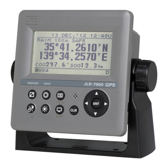
Section 2 Names and Functions of the Components 2.1 NWZ-4610 DISPLAY UNIT Unit (Front) Display Information received from the GPS sensor, the equipment setting screen, etc. are displayed. Speaker Operation panel Operation panel Operation Name Functions panel Power/ Use this key to turn on the power. Adjust the Contrast key contrast. - Page 36 Reading the Display ● RAIM Accuracy level Display the preset accuracy level In operation: 10m/30m/50m/100m RAIM OFF: "-" Date Time U: UTC time SAFE:No faulty satellite L: Local time CAUTION:RAIM impossible UNSAFE:Presence of fault satellite Display area Freeze indicator During operation, the black part moves.
-
Page 37: Jlr-4341 Dgps Sensor
2.2 JLR-4341 DGPS Sensor Radome 6-pin Connector Outside diameter: Approximately 19 mm Base Mounting Screw 1-inch 14UNS-2B Data Cable 15 m Outside diameter: Approximately 6 mm 2.3 JLR-4340 GPS Sensor Radome 6-pin Connector Outside diameter: Approximately 19 mm Base Mounting Screw 1-inch 14UNS-2B Data Cable 10 m Outside diameter: Approximately 6 mm... -
Page 39: Section 3 Display Screen
Section 3 Display Screen Each screen is detailed in this section. 3.1 Display Screen The screen is switched each time is pressed. Users can also determine not to display unnecessary screens. The CDI screen and GPS information screen are provided with sub-screens which can be selected by pressing 1) Navigation Screen This screen displays information such as the own ship's position (Refer to section 2.1 for detail). - Page 40 5) CDI screen Deviation from the route Deviation from the route is displayed. DRG and DTG can be displayed by pressing Steering direction Waypoint number Waypoint Own ship's position "-": less than 1 knot Width of the route 6) Distance (Trip) screen Trip is displayed.
- Page 41 9) Waypoint Information screen The waypoint screen can display the waypoint number, route number and waypoint position. Waypoint number Route number Waypoint position Memo VTD (Speed of the destination component) VTD (An acronym of "Velocity Toward Destination) This in an index that shows how fast the boat is approaching toward the destination in the unit of knot when it is navigation at a given bearing angle and speed.
-
Page 43: Section 4 Operation
Section 4 Operation 4.1 Menu List Main Menu Sub Menu Range Note DISPLAY CONTRAST 1-13 4.9.1 DIMMER MAXIMUM 4-13 4.9.2 DIMMER TYPICAL 3-12 4.9.2 DIMMER MINMUM 2-11 4.9.2 CLICK SOUND ON/OFF 4.9.3 DISPLAY SELECTION 4.9.4 DISPLAY1 4.9.4.1 SEGMENTATION1 4.9.4.2 DISPLAY 4.9.4.2 OWN SHIP POS※1/COG/SOG... - Page 44 Main Menu Sub Menu Range Note DISPLAY2 Same as DISPLAY 1 4.9.4.1 DISPLAY3 Same as DISPLAY 1 4.9.4.1 DISPLAY4 Same as DISPLAY 1 4.9.4.1 DISPLAY5 Same as DISPLAY 1 4.9.4.1 DISPLAY6 Same as DISPLAY 1 4.9.4.1 BACK LIGHT WHITE/ORANGE 4.9.5 PLOT WAYPOINT MARK ○...
- Page 45 Main Menu Sub Menu Range Note SYSTEM UNIT 4.10.1 DIST/SPD NM,kn / km,km/h / mi.mi/h / m,m/s 4.10.1 ANT HEIGNT m / ft / fm 4.10.1 TIME DIFF -13:00 - +13:30 4.10.2 YY-MMM-DD HH:MM/DD DATE DISP MMM,'YY HH:MM/MMM 4.10.3 DD,'YY HH:MM MAG CORR 4.10.4 DISPLAY...
- Page 46 Main Menu Sub Menu Range Reference/Note ARRIVAL/ANCHOR ARRIVAL/ANCHOR/OFF 4.12.4 SOUND ON/OFF 4.12.8 LCD COLOR ON/OFF 4.12.8 ON/OFF 4.12.5 SOUND ON/OFF 4.12.8 LCD COLOR ON/OFF 4.12.8 ON→OFF/OFF→ON/OFF⇔O DGPS 4.12.6 N/OFF SOUND ON/OFF 4.12.8 HDOP OVER/OFF 4.12.7 OVER 1 - 20 4.12.7 SOUND ON/OFF 4.12.8...
- Page 47 Main Menu Sub Menu Range Reference/Note INTERFACE DATA I/O 4.15.5 DATA IN/OUT1 NMEA/JRC/IEC 4.15.5 NMEA 4.15.5 DATA IN/OUT SEND/RECEIVE 4.15.5 VERSION 1.5/21./2.3/4.0 4.15.5 SEND Only SENTENCE SENTENCE LIST 4.15.5 SEND Only BIT RATE 4800/9600/19200/38400 4.15.5 4.15.5 DATA IN/OUT SEND/RECEIVE 4.15.5 BIT RATE 4800/9600/19200/38400 4.15.5...
- Page 48 Main Menu Sub Menu Range Reference/Note MAINTENANCE INPUT DATA 4.15.9.1 DIAGNOSIS 4.15.9.2 DISPLAY DIAG 4.15.9.2 SENSOR DIAG 4.15.9.2 MONITOR TEST 4.15.9.2 BUZZER TEST 4.15.9.2 ERROR LOG 4.15.9.3 ALARM 4.15.9.3 ERROR LOG 4.15.9.3 SOFT VERSION 4.15.9.4 DISPLAY VER 4.15.9.4 APP VER 4.15.9.4 SERIAL NUMBER 4.15.9.4...
-
Page 49: Basic Operation
4.2 Basic Operation 4.2.1 Turning the Unit On When the main power is turned on, the power to the display unit is automatically turned on. In the state in which the power is turned off by the display unit key operation, pressing the turns on the power. - Page 50 1. A receiver is selected. Select the receiver connected. 1.RECEIVER SELECT : JLR-4341▼ When JLR-4341/4340 are selected by mistake, turn OFF a power immediately and carry out action When selected except JLR-4341/4340 by mistake, turn OFF a power and carry out power ON again.
-
Page 51: Startup (Standard)
4.2.1.1 Startup (Standard) If all the self-check results are ‘OK’, the screen is automatically changed to the normal screen. 4.2.1.2 Startup (Error-1) If the self-diagnosis results are errors “NG,” the results are displayed as follows. Supplement When any abnormality (NG) is found, contact JRC or one of our agents. 4.2.1.3 Startup (Error-2) Messages shown below may be displayed during sensor diagnostics. -
Page 52: Turning Off The Power
4.2.2 Turning off the power If the key and the key are pressed and held down simultaneously, the power will be turned off and the screen display will turn off. Supplement The power may be turned on due to the release timing of your finger. In this case, first release the and then release the 4.2.3... -
Page 53: Turning Off The Buzzer
4.2.5 Turning off the buzzer Buzzer sound can be turned off by pressing The buzzer sounds if an error occurs. 4.2.6 Switching display The display screen is switched whenever is pressed. 4.2.7 Alert display When an alert occurs, the event is notified with a popup menu and alert sound. When is pressed, the popup menu is cleared and the buzzer sound stops. -
Page 54: Selecting Items From The Menus
4.2.8 Selecting items from the menus This section shows the procedure for selecting items from the menus and determining the selection. Procedure Press Move the cursor to a required item by using and press . The item is selected and a submenu is opened to enable selection of details. -
Page 55: Entering A Numeric Value
4.2.9 Entering a numeric value This section describes the procedure for entering a numeric value. Procedure Move the cursor to the field in which a value is to be entered by using Set a numeric value to be entered by using and press Move the cursor to the right most field and press . -
Page 56: Plot Screen Operation
4.3 Plot Screen Operation The plot screen can display own ship's position, track, active route, waypoint and cursor information. Display is fixed to North Up. Distance from own ship to Cursor Lanitude and Longitude cursor. Bearing from own ship to Cursor cursor. -
Page 57: Centering The Own Ship On The Screen
4.3.3 Centering the Own Ship on the Screen The position of the own ship can be moved to the center of screen. Procedure Press the key. Own ship will be displayed at the center of the screen. Supplement When own ship reaches the edge of the screen, it automatically returns to the center of the screen. -
Page 58: Setting The Track Period
4.3.6.1 Setting the Track Period Memory intervals can be set to units of time or of distance. The following periods can be set: Time: Can be set in 1 second increments between 1 second to 60 minutes. Distance: Can be set in 0.01 NM increments between 0.01 to 99.99 NM. Procedure Press the key to display the main menu. -
Page 59: Changing Waypoint Symbol
4.3.7.1 Changing Waypoint Symbol Set the default value of the symbol to be displayed for the waypoint. The symbol can also be changed individually from the waypoint list. In order to change symbols, you must switch the unit to non-IMO mode. Procedure Press the key to display the main menu (standard mode). -
Page 60: Changing Route Into Track
4.3.8 Changing Route into Track A track can be registered into a destination list, and it can change into a route. Registration interval which registers a track into a destination list: Time: It can set up by one second bit in 1 second - 60 minutes. Distance: It can set up by 0.01NM bit in 0.01NM - 99.99NM. -
Page 61: Registering Waypoints
4.4 Registering Waypoints Waypoints must be registered to the waypoint list to start navigation. Up to 1,000 waypoints can be registered in this unit. 4.4.1 Displaying the Waypoint List The registered waypoints can be displayed. The waypoint number 000 is only for a MOB position. Even if the MOB position is not registered, 000 displays. -
Page 62: Registering The Own Ship Position
Press the key to select "WPT/ROUTE" and "WPT LIST," and press the key. Move the cursor to the number you wish to register, and press the key. 4. The way point registration screen will be displayed. LAT/LON Latitude longitude is registered in the input of a key. -
Page 63: Registering A Bearing And Distance From A Specified Position
4.4.2.3 Registering a Bearing and Distance from a Specified Position A position can be specified as a start point, and then another position defined by its bearing and distance from said start point can be registered in the waypoint list. A start point can be selected from the following three items. -
Page 64: Editing Waypoint Information
4.4.3 Editing Waypoint Information Registered waypoint information (symbol shape, comment, waypoint position) can be edited. Waypoints on routes that are currently being executed cannot be edited. Procedure Press the key to display the main menu. Press the key to select "WPT/ROUTE" and "WPT LIST" and display the waypoint list. Press the key to move the cursor to the waypoint number you wish to edit, and press the key. -
Page 65: Copying Waypoint Information
4.4.4 Copying Waypoint Information To copy waypoint information to another waypoint number, use the number to which the information is to be copied as the waypoint number in waypoint information. The source information is not deleted but is copied. Please refer to "4.4.3 Editing waypoint information (1)To edit the waypoint number"... -
Page 66: Route Planning
4.5 Route Planning Routes can be created using the registered waypoints. A maximum of 20 routes can be created with this unit, with each route having up to 50 waypoints. Arrival circle radii, route widths, planned speed and distance calculation method can be set for each route. -
Page 67: Creating Routes
Press the key to select "WPT LIST and press the key. The route waypoints are listed Waypoint of the registered route Route waypoints list 4.5.2 Creating Routes To create a route, decide the route number and select the waypoints to be used as way points in order. - Page 68 The waypoint list of route will be displayed. Press the key to select the top of blank area, and press the key. The following items can be set in WPT No. WPT No: You can set the waypoint number. WPT LIST: You can select waypoint numbet from waypoint list.
-
Page 69: Editing Routes
4.5.3 Editing Routes Route number and route information can be changed, and waypoints can be skipped, added, or deleted. 4.5.3.1 Changing Route Number The same information is entered in the input route number. Information about the route number before change also remains. -
Page 70: Adding Route Waypoints
Press the key to select "WPT LIST," and press the key. Waypoint List will be displayed. Move the cursor to the waypoint number you wish to skip, and press the key. Press the key to select "STATUS", "SKIP" and press the key. -
Page 71: Deleting Route Waypoints
Ex 1) Adding a waypoint between 1 and 2 Move cursor to second waypoint + for 1 second Waypoint List Waypoint Information screen Ex 2) Adding a waypoint at the start. Move cursor to first waypoint + for 1 second Ex 2) Adding a waypoint at the end. -
Page 72: Copying Routes
Press the key to select "WPT LIST," and press the key. The waypoint list of route will be displayed. Press the to select the waypoint you wish to delete, and press the key. Press the key to select "DELETE" and press the key. -
Page 73: Deleting Routes
4.5.5 Deleting Routes Routes registered between 1 and 20 can be deleted. The waypoint on the route to be deleted can also be deleted at the same time. If the waypoint is also detected, the waypoint used on the different route is not deleted. ... -
Page 74: Performing Navigation
4.6 Performing Navigation Registered and temporary routes can be started. Routes can be selected by the following methods. (1) Selecting a route from the route list (2) Selecting a waypoint with the GOTO key (3) Selecting a route with the GOTO key (4) Creating a temporary route with the GOTO key ... -
Page 75: Selecting A Waypoint/Route With The Goto Key
smoothed. It is recommended to set this value only if the calculation result varies largely. (4) ROUTE You can set whether to start or stop navigation. START: Navigation is started. END: Navigation is stopped. (1) To set waypoint update method Select "LEG CHANGE", select the waypoint update method, and press the... - Page 76 (2) Enter the waypoint number If the waypoint number is known, enter the number and set the waypoint. Press the key. Press the key to select "WAY POINT NUM," and press the key. Press the key to enter the waypoint number, and press the key.
- Page 77 Press the key again at the final waypoint to decide the temporary route Press the key to set "RADIUS", "WIDTH" and "GC/RL", and press the key. Please refer to "4.5.2 Creating Route" for details. Press the key to select "START", and press the key.
-
Page 78: Stopping Navigation
4.6.3 Stopping Navigation Navigation currently underway can be stopped. To end navigation, use two methods: selecting in the menu and holding down the key. 4.6.3.1 Ending Navigation with GOTO Key Procedure Press and hold down the key (3 seconds or more). When the following popup is displayed, press “YES”. -
Page 79: Entering Comments
4.7 Entering Comments Comments of up to 8 characters can be added to waypoints. Use the keys to select from character list and enter characters. 4.7.1 Text Entry The entry example will show how to input "ABC" on the waypoint comment entry screen. Procedure "COMMENT"... -
Page 80: Deleting Text
4.7.2 Deleting Text The entered characters can be deleted. 4.7.2.1 Deleting One Character One character in a comment is deleted. One character before the cursor is deleted. If the cursor is located at the start, the first character is deleted. -
Page 81: Adding Text
4.7.3 Adding Text Characters can be added to comments. Procedure When the cursor in the character selection field is located at the top, press the key to move the cursor to the comment entry field. Press the key to move the cursor to the position where you wish to add a character. Press the key to move the cursor to the character selection field. -
Page 82: Mob
4.8 MOB The MOB (Man Overboard) function is used to save the position at which a person or object has fallen overboard. This function allows rapid return to that position. The MOB function is valid on all screens. - If MOB is performed, a MOB mark will be displayed on a Man Overboard position and the route which made the Man Overboard position the destination will be performed. -
Page 83: Setting Display
4.9 Setting Display When “Display” is selected on the main menu, a display menu is displayed. On the display menu, LCD (contrast and back light), click sound, screen selection, and back light color can be set. Each submenu is outlined below. 1) LCD: Adjusts the contrast and sets the back light level. -
Page 84: Setting A Click Sound
4.9.3 Setting a click sound Turn on/off a key-operation click sound. ON: Enables a click sound. When the key is pressed, a click sound is emitted. OFF: Disables a click sound. Procedure Display a main menu by pressing Select “DISPLAY” and “CLICK SOUND” in that order by using Select “ON”... -
Page 85: Step2 Selecting A Screen Structure
Select a display from DISPLAY1 to DISPLAY6 4.9.4.2 STEP2 Selecting a screen structure The screen structures of each display screen include customized screens that can be set freely, special screens that do not allow any setting, and graphic screens. Select a screen structure. When display structure selection is set to “OFF”, the display screen cannot be registered. -
Page 86: Step3 Selecting Display Contents
Procedure Select a display screen by referencing “STEP1”. Select a screen structure from “SEGMENTATION1”, “SEGMENTATION2”, “SEGMENTATION3”, “SEGMENTATION4”, “SPECIAL”, “GRAPHIC” and "OFF" by using and press Select SEGMENTATION1, SEGMENTATION2, SEGMENTATION3, SEGMENTATION4, SPECIAL, or GRAPHIC. 4.9.4.3 STEP3 Selecting display contents Select as many display contents as the number of screens that are created by segmentation. For instance, for a 2-segmentation screen, select the display content for one half of the screen and then select the display content for the other half of the screen (see the diagram below). - Page 87 Procedure Select a screen structure by referencing “STEP1” and “STEP2”. Customized screen Select a screen section to be displayed by using and press Select the screen section from the following: segmentation1 screen: “DISPLAY’ segmentation2 screen: “DISPLAY 1/2” “DISPLAY 2/2” segmentation3 screen: “DISPLAY 1/3” “DISPLAY 2/3” “DISPLAY 3/3” segmentation4 screen: “DISPLAY 1/4”...
-
Page 88: Selecting A Back Light Color
Select “ON” or “OFF” under “AUTO SCREEN” by using and press Select “SOUND1” , “SOUND2” and "OFF" under “SOUND” by using and press Select “TIME” by using Enter a switching time by using and press Starting an auto screen Press and hole for 1 second or more. -
Page 89: System Settings
4.10 System Settings Select "SYSTEM" on the main menu to display the system setting screen. To change the system settings, place the unit in maintenance mode. An overview of each submenu is as follows. (1) UNIT: The unit of speed and heigtt is set. (2) TIME DIFF: Set the time difference between UTC and local time. -
Page 90: Setting The Date Display
4.10.3 Setting the Date Display You can set the date display format to “DD MMM,'YY,” “MMM DD,'YY,” or “'YY-MMM-DD.” YY: Year MMM: Month DD: Day Procedure Refer to "4.15.1 Change to a maintenance mode" and display the maintenance menu. Press the key to select "SYSTEM"... -
Page 91: Displaying As Loran C Time Differnce
4.10.5 Displaying as Loran C time differnce Own ship position (latitude and longitude) can be displayed as LORAN C time difference. Procedure Refer to "4.15.1 Change to a maintenance mode" and display the maintenance menu. Press the key to select “SYSTEM,” “LORAC C,” “LORAN C” in order. Press the key to select “ON.”... -
Page 92: Language Settings
4.11 Language Settings You can set the display language to nine languages (English/Japanese (katakana)/German/French/Italian/Norwegian/Spanish/Vietnamese/Indonesian). To change the language, place the unit in the maintenance mode. Procedure Refer to "4.15.1 Change to a maintenance mode" and display the maintenance menu. Press the key to select "LANG."... -
Page 93: Alert Settings
4.12 Alert Settings 7 types of alerts can be configured. When the set alert occurs, the pop-up and the alert icon " " on the status bar alert the occurrence of an alert. The screen lighting color can also be changed. Pressing the key stops pop-up, buzzer sound, and screen lighting, but the icon continues appearing until the alert has been resolved. -
Page 94: Setting A Vessel Speed Alert
4.12.2 Setting a vessel speed alert When the vessel speed reaches the set range, the alert is issued. The range can be selected from OVER, UNDER, IN RANGE, and OUTRANGE. OVER: An alert is issued when the vessel speed reaches or exceeds the set speed. UNDER: An alert is issued when the vessel speed is equal to or slower than the set speed. -
Page 95: Setting Xtd Alert
When the arrival or anchor alert occurs, the alert icon is displayed. Arrival Anchor Arrival icon Anchor icon 4.12.5 Setting XTD Alert An alert occurs when own ship exits the route. Procedure Refer to "4.15.1 Change to a maintenance mode" and display the maintenance menu. Press the key to select "ALARM"... -
Page 96: Setting Hdop Alert
4.12.7 Setting HDOP Alert An alert occurs when the GPS positioning HDOP value exceeds the set value. Procedure Refer to "4.15.1 Change to a maintenance mode" and display the maintenance menu. Press the key to select "ALARM" and "HDOP" in order. Press the key to select "OFF", or "OVER,"... -
Page 97: Gps/Beacon/Sbas Settings
4.13 GPS/Beacon/SBAS Settings Select "SENSOR" on the main menu to display the GPS/beacon/SBAS setting screen. The items that can be set will vary depending on the connected sensor. The unit must be placed in maintenance mode to change the GPS/Beacon/SBAS settings. An overview of each submenu is as follows. -
Page 98: Setting Fix Mode
4.13.2 Setting FIX Mode You can select FIX mode to AUTO, 2D, or 3D. The selections are as follows: (1) AUTO: Positioning mode is automatically switched between 3D and 2D, with the optimal method being used. (2) 2D: 2D positioning performed. (3) 3D: 3D positioning performed. -
Page 99: Setting Position, Speed, And Course Smoothing
4.13.5 Setting Position, Speed, and Course Smoothing Smoothing can be applied to measured positions, speeds, and courses. The higher the smoothing value, the smoother the results will be, but the greater time lag. Conversely, if the smoothing value is set low, a great number of changes will occur, but there will be little time lag. -
Page 100: Initializing The Gps
4.13.7 Initializing the GPS GPS initialization can be performed. An overview of submenus on the GPS initialization screen is as follows. (1) LATITUDE: Enter the approximate ship latitude. (2) LONGITUDE: Enter the approximate ship longitude. (3) HEIGHT: Enter the estimated height above the draft line of the sensor. This height is used in 2D positioning. -
Page 101: Setting Beacon
4.13.8 Setting Beacon Beacon setting can be performed. Manual An overview of submenus on the beacon setting screen is as follows. (1) STATION SELECT: Set the beacon station selection method. AUTO: The best beacon station is selected automatically from the GPS position. MANUAL: You can set the frequency and bit rate manually. -
Page 102: Setting Sbas
4.13.9 Setting SBAS SBAS setting can be performed. The sensor must support SBAS to perform SBAS setting. An overview of submenus on the SBAS setting screen is as follows. (1) SBAS SEARCH: The SBAS satellite can be set. AUTO: The SBAS satellite is automatically set. -
Page 103: Beacon Information
4.14 Beacon Information When the beacon information is set to "ON" based on "4.13.8 Setting beacon", the beacon information (Type16 massage) from the beacon broadcast stations can be displayed. Procedure Refer to "4.15.1 Change to a maintenance mode" and display the maintenance menu. Press the key to select "BEACON."... -
Page 104: Equipment Configuration
4.15 Equipment Configuration After completing the installation that is described in Chapter 6, check the operation and set the details. In the installation setting, implement the following operations according to the system specification of the vessel. 1) Changing to a maintenance mode 2) Setting a model 3) Selecting a dimmer unit 4) Setting dimmer control linkage and data sharing... -
Page 105: Setting A Model
4.15.2 Setting a model Set this display unit as a GPS display unit. When the model is set, the setting contents are initialized. When setting up to "GPS" by model setup, perform receiver selection like the first time power ON (refer to "4.2.1 Turning the Unit On"). -
Page 106: Dimmer Linked Control And Data Sharing With Rs-485
4.15.4 Dimmer linked control and data sharing with RS-485 By connecting display units with RS-485 network, dimmer control can be linked and data can be shared. To connect display units with RS-485 network, the display units must be identified by setting RS-485ID in each display unit. -
Page 107: Setting Rs-485Id
4.15.4.1 Setting RS-485ID To identify a display unit on the RS-485 network, set an ID for each display unit. To use RS-485, an ID must be set. Avoid duplication of ID among the display units. Otherwise, data and dimmer linkage are not possible. Available IDs are from 1 to 10. -
Page 108: Sharing Data
4.15.4.4 Sharing data Data can be shared among the display units that are connected through the RS-485 network. Set the data to be transmitted. Although setting for reception is not necessary, the baud rate must be standardized among the display units. For the linkage, set RS-485ID by referencing "4.15.4.1 Setting RS-485ID”. -
Page 109: Setting A Serial Port
4.15.5 Setting a serial port This display unit is equipped with three serial ports to send and receive data with external units. Since each port can be set for input or output, set according to the purpose. However, as input/output of data IN/OUT1 and data IN/OUT2 are commonly set, they cannot be set individually. - Page 110 Refer to "4.15.1 Change to a maintenance mode" and display a maintenance menu. Select “INTERFACE” and “DATA I/O” in this order by using Select the output format to be set by using Selecting NMEA Select “SEND” from “DATA IN/OUT” by using When an output version is selected by using , a sentence list is displayed.
-
Page 111: Setting Reception
4.15.5.2 Setting reception In the reception setting, set a baud rate. A JRC format cannot be selected as the format. There is no need to set a sentence or a cycle. Procedure Setting port Select an output format Select RECEIVE Select BIT RATE Refer to "4.15.1 Change to a maintenance mode"... -
Page 112: Setting Contact Output
4.15.7 Setting Contact Output The following contact outputs can be set for contract output: Log Pulse (200 pulse/NM), Log Pulse (400 pulse/NM), and Alert. An overview of the contact output submenu is as follows. LOG(200p/NM): 200 pulse/NM log pulse is output. LOG(400p/NM): 400 pulse/NM log pulse is output. -
Page 113: Checking The Input Port
Self-diagnosis of the display unit can be performed and the result can be displayed. The following items can be diagnosed. 1) ROM, RAM, and serial port of the display unit 2) Sensor (Only JLR-7900) 3) Monitor (LCD) The entire screen is highlighted repeatedly such as black to white, white to black. -
Page 114: Displaying An Alert
4.15.9.3 Displaying an alert The current alert and past alerts can be displayed. Up to 40 past alerts can be stored and when the number of alerts exceeds 40, alerts are deleted from the oldest one. Procedure Refer to "4.15.1 Change to a maintenance mode" and display a maintenance menu. Select “MAINTENANCE”... -
Page 115: Displaying The Software Version
4.15.9.4 Displaying the software version The software version, serial number and bar code number of the display and sensor unit can be displayed. It is only JLR-4341/JLR-4340 that the serial number and bar code number of the sensor unit can be displayed. -
Page 116: Performing A Demo
4.15.11 Performing a Demo Through a demonstration, display and external output are enabled in the same way as the actual equipment operation. The following demo types can be set. STATIC: Remains stationary. STRAIGHT: Goes in straight lines. Set the speed and direction. RIGHT: Turns right. -
Page 117: Setting The Gps Sensor Number
4.15.13 Setting the GPS Sensor Number A number can be assigned to each GPS when there are two GPS sensors. This number used for Remote Maintenance System data, so always perform GPS number configuration. When only one GPS is used, set the number to No1. ... -
Page 118: Setting Sensor Position / Ccrp
4.15.15 Setting Sensor Position / CCRP · You can set the ship size, CCRP position, and GPS sensor position. · The CCRP position and GPS position are set on a coordinate system with the center of the ship as the point where the axes cross. ·... -
Page 119: Inputtig/Outputting Waypoint, Route And Track
4.15.17 Inputtig/Outputting Waypoint, Route and Track 4.15.17.1 Outputting Waypoint, Route and Track A waypoint list and the destination of a route list, a route, and a trip can be outputted to external PC. The ports used with an output are DATA IN/OUT2 and 3. By outputting in an exclusive format, it can save by a CSV file. -
Page 120: Inputting Waypoint, Route And Trip
2) When outputting in an exclusive format Refer to "4.15.1 Change to a maintenance mode" and display the maintenance menu. Press the key to select "INTERFACE" "DATA I/O" and press the key. Select "ROUT WPT" from DATA IN/OUT2 and DATA IN/OUT3, and press the key. - Page 121 2) When outputting in a NMEA format Start the tool of PC and select a output file. Refer to "4.15.17.3 How to Use Exclusive PC Tool" for how to use PC tool for exclusive use. Refer to "4.15.1 Change to a maintenance mode" and display the maintenance menu. Press the key to select "INTERFACE","DATA I/O"...
-
Page 122: How To Use Exclusive Pc Tool
4.15.17.3 How to Use Exclusive PC Tool The usage of "JrcRouteTrans.exe" which is a tool for exclusive use of the input and output of the "route, waypoint and track" are described. (1) Preparation Installation is unnecessary. Copy "JrcRouteTrans.exe" to arbitrary folders. (2) When outputting from a display Port setting Data transmission /... - Page 123 1. Select "PC=>Display" from "TX/RX". 2. Press "Select files to send". "add" is pressed, a transmitting file is selected and it adds to a transmitting file list. When a transmitting file list has an unnecessary file, select a file and press "del". 3.
- Page 124 2) Route file The example of a route file is displayed below. Plan ship speed The number of It is the same ship waypoint in a speed altogether route The destination within the same Unit : [knot] fixation number in a route Unit : [NM] fixation route.
-
Page 125: Section 5 Maintenance And Inspection
Section 5 Maintenance and Inspection Proper maintenance may greatly affect the lifespan of the equipment. In order to maintain the equipment in peak state, perform the following regularly. WARNING Do not perform internal inspections or modifications of the equipment. Inspection or modification by unauthorized personnel may result in fire, electric shock, or equipment failure. -
Page 126: Alerts
5.2 Alerts Refer to "4.15.9.3 Displaying an alert" and check if any alert is given or not. If it is, check the details referring to the list shown below. Alert List Message Message Contents Causes Number Speed alert occurs TRIP Trip alert occurs Arrival Wpt Arrival at waypoint... -
Page 127: Troubleshooting
5.3 Troubleshooting 5.3.1 Troubleshooting WARNING Do not perform internal inspections or modifications of the equipment. Inspection or modification by unauthorized personnel may result in fire, electric shock, or equipment failure. Please consult with JRC or an affiliate to perform internal inspections or repair. -
Page 128: Repair Unit
5.3.2 Repair Unit Repair units and their models are shown below. Name Model Notes DISP-DSP CMJ-562 NWZ-4610 Display Unit LCD UNIT CCN-423 NWZ-4610 Display Unit POWER SUPPLY UNIT CMP-490 NWZ-4610 Display Unit Beacon Antenna CAW-1 For JLR-4341 DGPS Sensor Beacon Controller CMA-920 For JLR-4341 DGPS Sensor Fuse... -
Page 129: Section 6 Installation
Section 6 Installation WARNING To connect the sensor other than JLR-4341/4340, set the supply voltage of the display unit to 12 VDC (10.8 to 15.6 VDC) for use. Failure to do so causes fire, electric shock or failure. CAUTION Please consult with JRC or our agents to perform installation. Installation by unauthorized personnel may result in malfunction. -
Page 130: Gps Sensor Installation
GPS Sensor Installation 6.1.1 Selecting the Position for Installation WARNING To connect the sensor other than JLR-4341/4340, set the supply voltage of the display unit to 12 VDC (10.8 to 15.6 VDC) for use. Failure to do so causes fire, electric shock or failure. -
Page 131: Sensor Installation Procedure
6.1.2 Sensor Installation Procedure The sensor base contains 1 inch-14UNS-2B screw holes. It can be attached to poles with cut male screws, or off-the-shelf adapters. (1) When performing attachment, always hold and turn the sensor base. Holding and turning the radome may result in a large amount of force applied at the junction of the base and the radome, resulting in damage to the sensor. -
Page 132: Installation Of The Sensor On The Mast
6.1.3 Installation of the Sensor on the Mast Use a screw adapter (optional component or equivalent) to connect the sensor to the mast. The diagram shows the JLR-4341, but these instructions apply equally to the JLR-4340 as well. JLR-4341 DGPS sensor Fitting band MPBP02520 Screw adapter... -
Page 133: Installation Of The Sensor To Pass A Cable Through A Pole
6.1.4 Installation of the Sensor to Pass a Cable through a Pole It is possible to pass a cable through a pole, when DGPS sensor attached to poles with cut male screws. (1 inch-14 UNS-2A). In this case, cable guard rubber (accessory) is used. (1) The cable is installed as following figure. - Page 134 (3) Attach the sensor to the poles with cut male screw. Be sure to deburr the pole end face (see below). Be sure to deburr end faces 25 mm 1 inch-14UNS-2A Example of cutting pole (4) When performing attachment, always hold and turn the sensor base. Holding and turning the radome may result in a large amount of force applied at the junction of the base and the radome, resulting in damage to the sensor.
-
Page 135: Affixing Display Unit Nameplate Labels
When you use the old receiver (except JLR-4341 / 4340 receiver), use the seal of "NWZ-4610 GPS." Old sensor JLR-7600 JLR-7900 Product Nameplate (Accessory) Display Unit Front 6.2.2 Affixing Model Identification Plate Peel the label of the equipment to be used from the accessory model identification plate, and affix it over the upper left blank part of the unit nameplate at the center of the rear case. -
Page 136: Display Unit Installation
Display Unit Installation 6.3.1 Selecting the Position for Installation WARNING Install this display at least 1 m away from any magnetic compasses. Installation near a magnetic compass may interfere with the magnetic compass, resulting in an accident. Do not use this display at the voltage other than its rated voltage. Doing so results in fire, electric shock or failure. -
Page 137: Mounting The Display Unit Using A Rack
6.3.2 Mounting the display unit using a rack Use the following procedure. (1) Fix the desktop rack at the required installation position by using the mounting screws (φ4~6 screw or wood screw, L>=15mm, provided by the shipyard). (2) Insert the front panel into the main unit. (3) Attach the rotational washer on the side of the main unit. - Page 138 285 or more 190 or more Required installation space Mount (bottom) (Unit: mm) 6-10...
-
Page 139: Mounting Using A Flash Mount
6.3.3 Mounting using a flash mount Use the following procedure. See the diagram below for the mounting space and mounting holes. (1) Insert the main unit in the installation location. (2) Fix the main unit using screws (φ4 screw or wood screw, L>=10mm, provided by the shipyard). - Page 140 Provide maintenance space 180 or more (Square hole) Mounting hole ※About the corner C11, (Screw pitch) may want to cut φ25 (Unit: mm) 6-12...
-
Page 141: Removing The Display Unit By Flash Mounting
6.3.4 Removing the display unit by flash mounting Use the following procedure to remove the display unit. (1) Insert a hexagonal wrench into the holes (2) at the bottom of the front panel. (2) Remove the front panel by pressing down the hexagonal wrench. Mounting wall Front panel Press down... -
Page 142: Cable Connection
Cable Connection Unit (Rear Connector) [DATA 1] Share data between display units [SENSOR/DATA 2] [TERM.] Connect to the GPS sensor Turn ON and OFF terminal resistance for DATA1 connection [DC12/24V DATA] Power Input Terminal Used fro power input to unit. Be sure to connect specified data power cable. -
Page 143: Dc12/24V Data Connector
6.4.1 DC12/24V DATA Connector In this display, the voltage supplied to the display is supplied to a receiver as it is. When you use receivers except JLR-4341/JLR-4340, set the power supply of a display to DC12V. Supply of 24V will damage a receiver. Display Unit Rear: Connector Pin Number ⑭... - Page 144 [Input/Output Condition for Serial Transmission] The data power cable (CFQ-5766) has three serial transmission channels. The input/output settings for DATA I/O "1" and "2" are linked to each other. As listed below, four connections and settings can be made. For the input/output settings for channels, see "4.15.5 Setting a serial port". Data Power Cable CFQ-5766A: 2 m (Accessory) CFQ-5766D: 10 m (Option)
- Page 145 [Input/Output Circuit] NWZ-4610 Display Unit [Contact Output] Relay 3: Orange 4: Yellow 5: Green Contact maximum 30 VDC/1.0 A [Contact Input/Analog Input] NCM-227 Dimmer Unit 6: Blue 7: Purple or Contact Connection [Serial Transmission] IEC61162-1(NMEA) Output Setting SD-A Input SD-B IEC61162-1(NMEA) Input Setting SD-A...
-
Page 146: Data1 Connector
6.4.2 DATA1 Connector TERM. Switch Display Unit Rear: Connector Pin Number ① ④ ② ③ Display Unit Rear CFQ5769 Data Cable CFQ-5769: 3 m (Option) Terminal Name Explanation Number (CFQ-5769) Brown SD1-A Serial Connect to the display unit for serial transmission Transmission SD1-B RS-485... - Page 147 [T-SHAPED CONNECTOR] This T-SHAPED CONNECTOR can be used to extend cables and connect multiple units (up to 10 units). CFQ-5769 CFQ-5769 T-SHAPED CONNECTOR (option) Type name: AA-040404-MMM-TL Code: 5JCDX00071 CFQ-5769 [To Extend the Cable] CFQ-5769: 3 m x necessary number of cables T-SHAPED CONNECTOR: Same number as CFQ-5769 CFQ-5769: 3 m...
- Page 148 [To Connect Multiple Units] Up to 10 units can be connected. The number of cables and the number of cable adapters vary depending on the distance between display units. CFQ-5769: 3 m CFQ-5769: 3 m CFQ5768 CFQ5768 ・・ 3・4・5・6・7・8・9 ・・ Term.: ON (up) Term.: OFF (down) Term.: ON (up)
- Page 149 [To Group Dimmer Control] The following shows an example of grouping 10 units (maximum number of connections) into 3 units, 3 units, and 4 units. CFQ-5769: 3 m RS485ID: 01 RS485ID: 02 RS485ID: 03 12.3 12.3 12.3 Dimmer group: 01 Dimmer: Key Key operation RS485ID: 06...
-
Page 150: Sensor/Data2 Connector
6.4.3 SENSOR/DATA2 Connector In this display, the voltage supplied to the display is supplied to a receiver as it is. When you use receivers except JLR-4341/JLR-4340, set the power supply of a display to DC12V. Supply of 24V will damage a receiver. Display Unit Rear: Connector Pin Number ①... - Page 151 For cable length of more than 15 m Use the junction box (NQE-7700A) for connection. DGPS sensor: JLR-4341 GPS sensor: JLR-4340 GPS cable/CFQ-9002 Junction box/NQE-7700A Connect junction boxes by MPYCYS-7 (up to 50 m) [Coaxial Cable Kit Connection] When using a pre-existing coaxial cable, such as when switching from a JLR-6800, use a coaxial cable kit (NQD-4414).
-
Page 152: Optional Peripheral Connection
Optional Peripheral Connection 6.5.1 Sub-Display Connection The external output of a main display is connected to the input of a sub display. CFQ-5766A CFQ-5766A CQD-10 Main display Sub display A junction box (CQD-10) is used for connection. When you use it as a sub display, make a display type into a “sub”. The main and a sub can use it with every terminal. -
Page 153: Dimmer Unit Connection
6.5.3 Dimmer Unit Connection The brightness of the backlight can be changed at a location away from the display unit by connecting the dimmer unit (NCM-227). Connection example DATA1 NWZ-4610 Display Unit SENSOR /DATA2 DC12/24V DATA CFQ-5766A Data Power Cable (2 m) CQD-10 Junction Box... -
Page 154: Junction Box Connection
6.5.4 Junction Box Connection CAUTION The junction box rubber gasket (25 f gland side) fit 10 mm - 20 mm cables. How to Mount the Junction Box on a Flat Surface Securely mount the junction box on a given flat surface using self-tapping screws and flat washers as shown below. - Page 155 Pole Mounting Kit MPBP30608 Bracket SUS Hex Bolt M6 X 60 SUS Washer M6 SUS Spring Washer M6 SUS Nut M6 SUS Lock Nut M6 SUS Mast (26 mm - 53 mm) (Note) SUS: Stainless Steel To DGPS Sensor Gland 15f Perform waterproofing (1) or (2) below for the glands.
-
Page 156: Coaxial Cable Kit Connection
Internal Connection Connect the respective cables (cable from the DGPS sensor and extension cable) to the terminals provided in the junction box as shown in the following figure. JLR-4341 Junction Box DGPS Sensor Cable Line lengths: DGPS Sensor Terminal 55±5 mm Cable Black... -
Page 157: Output Buffer (Nqa-4351)
6.5.6 Output buffer (NQA-4351) An output buffer unit can be distributed NMEA data to external unit (Up to 12 units) Output buffer Up to 12 units : NQA-4351 NMEA Data 6.5.7 GPS Select Switch (Manual) (NCZ-1663) A GPS select switch (NCZ-1663) can be connected to output buffer (NQA-4351) unit and switched GPS units manually. - Page 158 6-30...
-
Page 159: Section 7 After-Sales Service
Section 7 After-Sales Service 7.1 Warranty ● Specific periods may vary based on our warranty policies, but the standard warranty period is one year from the date of purchase. 7.2 Repair parts stocking Period ● We keeps functional repair parts for this equipment (parts necessary for the functioning of this equipment) in stock for 10 years from the discontinuation of production. -
Page 161: Section 8 Disposal
Section 8 Disposal WARNING When disposing of the used lithium battery, place insulating tape over the battery terminals, or otherwise insulate the battery. Failure to do so may result in heating, explosion, or fire due to a shorted battery. 8.1 Disposal of the Equipment ●... -
Page 163: Section 9 Specification
Display Language: English/Japanese/Norwegian/French/German/Italian/Spanish/ Vietnamese/Indonesian Power Supply Voltage: DC12/24V (+30%, -10%) Power consumption: Less than 8 W (JLR-7900 [JLR-4341 connection]) Less than 7 W (JLR-7600 [JLR-4340 connection]) Less than 4 W (NWZ-4610) Dimension: 142(W) 142(H) 92(D) mm ... -
Page 164: External Interface
MSS*, ALR, APB, BOD, BWC, BWR, RMB, XTE, ZDG, AAM, RTE, WPL, Output Interval: 1s, 2s, 3s, 4s, 5s, 6s, 7s, 8s, 9s, OFF *Function only available on JLR-7900 Note) Some combinations of output sentence, bit rates, and output intervals may not be possible. (1-2) IEC ... -
Page 165: Jlr-4341 Dgps Sensor
9.2 JLR-4341 DGPS Sensor 9.2.1 Basic Specification (1)GPS Unit ・Reception Method :Multi channel 12ch + SBAS 1ch ・Reception Frequency :1575.42MHz±1MHz(C/A code) ・Maximum Number of Tracked Satellites :12 satellites ・Accuracy :13m 2DRMS (HDOP≦4 SA off) 2DRMS (Beacon selected) 2DRMS (SBAS selected) ・SBAS :WAAS、MSAS、EGNOS ・Geodetic datum... -
Page 166: Jlr-4340 Gps Sensor
9.3 JLR-4340 GPS Sensor 9.3.1 Basic Specification (1)GPS Unit ・Reception Method :Multi channel 12ch + SBAS 1ch ・Reception Frequency :1575.42MHz±1MHz(C/A code) ・Maximum Number of Tracked Satellites :12 satellites :13m 2DRMS (HDOP≦4 SA off) ・Accuracy 2DRMS (SBAS selected) ・SBAS :WAAS、MSAS、EGNOS ・Geodetic datum :Selection among 46 geodetic datum (2)Power Supply ・Power Supply Voltage... -
Page 167: Appendix
Appendix Appendix1 List of Geodetic System Screen Setting Geodetic System Display WGS-84 WGS-84 WGS-72 WGS-72 JAPAN Tokyo Datum NAD27 North American 1927 (USA) NAD27 North American 1927 (Canada, Alaska) EUROPE Europe 1950 (Europe) AUSTRA 66 Australian geodetic 1966 (Australia) OSGB-36 Ordnance Survey of Great Britain (England) NAD-83 NAD-83... -
Page 168: Appendix2 List Of Standard Terms, Units And Abbreviations
Appendix2 List of standard terms, units and abbreviations Term Abbreviation Term Abbreviation Acknowledge Change Acquire, Acquisition Circularly Polarised Acquisition Zone Clear Adjust, Adjustment Closest Point of Approach Compact Disk Read Only CDROM Memory Alarm ALARM Consistent Common CCRP Altitude Reference Point Amplitude Modulation Consistent Common CCRS... - Page 169 Term Abbreviation Term Abbreviation Distance Root Mean Square DRMS Geometric Dilution Of GDOP Precision Distance To Go Global Maritime Distress and GMDSS Drift DRIFT Safety System Dropped Global Navigation Satellite GNSS (for example, dropped EBL System origin) Global Orbiting Navigation GLONASS East Satellite System...
- Page 170 Term Abbreviation Term Abbreviation Interswitch Night Interval Normal NORM January North July North Up N UP June Not Less Than Label Not More Than Latitude Not Under Command Latitude/Longitude November Leeway October Limit Line Of Position Officer On Watch Offset OFFSET Long Pulse Long Range...
- Page 171 Term Abbreviation Term Abbreviation Radar Plotting Speed Radius Speed and Distance SDME Measuring Equipment Rain RAIN Speed Over the Ground Range Speed Through the Water Range Rings Stabilized STAB Raster Chart Display System RCDS Standby STBY Raster Navigational Chart Starboard/Starboard Side STBD Rate Of Turn Station...
- Page 172 Term Abbreviation Term Abbreviation Universal Time, Coordinated UTC Visual Display Unit Universal Transverse Voyage Mercator Voyage Data Recorder Unstabilised UNSTAB Warning WARNING Variable Range Marker Water Variation Waypoint Vector VECT Waypoint Closure Velocity Very High Frequency West Very Low Frequency Wheel Over Line Vessel Aground GRND...
-
Page 173: Appendix3 Default Value
Appendix3 Default Value Main menu Sub menu Sub menu Default DISPLAY CONTRAST DIMMER -MAXIMUM- DIMMER -TYPICAL- DIMMER -MINIMUM- CLICK SOUND DISPLAY SELECTION DISPLAY1 SPECIAL DISPLAY NAVIGATION INFO AUTO SCREEN SOUND TIME 1sec DISPLAY2 GRAPHIC DISPLAY PLOT AUTO SCREEN SOUND TIME 1sec DISPLAY3 GRAPHIC... - Page 174 Main menu Sub menu Sub menu Default ALARM SYSTEM SOUND LCD COLOR SPEED TRIP ARRIVAL/ANCHOR DGPS HDOP OVER OVER SOUND LCD COLOR SENSOR GPS MODE AUTO FIX MODE AUTO ELV MASK 5° HDOP SMOOTHING POSITION 10sec SPEED 10sec COURSE 10sec RAIM ACCURACY INITIALIZATION LATITUDE...
- Page 175 Main menu Sub menu Sub menu Default INTERFACE DATA I/O DATA IN/OUT1 NMEA NMEA DATA IN/OUT SEND VERSION SENTENCE ACK,APB,DTM,GGA, RMB,RMC,VTG,ZDA BIT RATE 4800 DATA IN/OUT2 NMEA NMEA DATA IN/OUT SEND VERSION SENTENCE ACK,APB,DTM,GGA, RMB,RMC,VTG,ZDA BIT RATE 4800 DATA IN/OUT3 NMEA NMEA DATA IN/OUT...
-
Page 176: Appendix4 Setting Value Memo
Appendix4 Setting Value memo Normal menu Main menu Sub menu Setting value DISPLAY - CONTRAST 1 2 3 4 5 6 7 8 9 10 11 12 13 DIMMER -MAXIMUM- 4 5 6 7 8 9 10 11 12 13 DIMMER -TYPICAL- 3 4 5 6 7 8 9 10 11 12 DIMMER -MINIMUM-... - Page 177 Main menu Sub menu Setting value English/Japanese/Norwegian/French/German/Italian/ LANG. LANG. Spanish/Vietnamese/Indonesian ALARM SYSTEM ON/OFF SOUND ON/OFF LCD COLOR ON/OFF SPEED OVER/UNDER/IN RANGE/OUT RANGE OVER UNDER MAXIMUM MINIMUM SOUND ON/OFF LCD COLOR ON/OFF TRIP OVER/OFF OVER SOUND ON/OFF LCD COLOR ON/OFF ARRIVAL/ANCHOR ARRIVAL/ANCHOR/OFF SOUND ON/OFF...
- Page 178 Main menu Sub menu Setting value DATA IN/OUT2 - NMEA - DATA IN/OUT SEND/RECEIVE VERSION 1.5/2.1/2.3/4.0 DATA IN/OUT2 SENTENCE SENTENCE BIT RATE 4800/9600/19200/38400 - DATA IN/OUT SEND/RECEIVE SENTENCE DATA IN?OUT2 SENTENCE BIT RATE 4800/9600/19200/38400 - INTERVAL OFF/4s ROUTE WPT - VERSION 1.5/2.1/2.3/4.0/JRC BIT RATE...
- Page 179 Main menu Sub menu Setting value RS-485 - NMEA - VERSION 1.5/2.1/2.3/4.0 RS-485 SENTENCE SENTENCE BIT RATE 38400/57600/76800/115200 - SENTENCE RS-485 SENTENCE BIT RATE 38400/57600/76800/115200 CONTACT INPUT DIMMER/ACK CONTACT OUTPUT 200PULSE/NM / 400PULSE/NM/ / ALARM/ OFF DIAGNOSIS - MAINTENANCE INPUT DATA -...
-
Page 180: Appendix5 List Of Symbols
Appendix5 List of Symbols Symbol name Symbol graphic Double circle Own ship - simplified symbol ◎ Small filled circle Past track ◎ Circle Waypoint ○ Long-dashed line Route ○ ○ Square with diagonal line Event Cross line User cursor Appendix-14... - Page 184 Not use the asbestos For further information,contact: URL Head office : http://www.jrc.co.jp/eng/ Marine Service Department 1-7-32 Tatsumi, Koto-ku, Tokyo 135-0053, Japan : tmsc@jrc.co.jp e - mail One - call : +81-50-3786-9201 ISO 9001, ISO 14001 Certified CODE No.7ZPNA4288 FEB. 2017 Edition 3...
Need help?
Do you have a question about the JLR-7900 and is the answer not in the manual?
Questions and answers