Table of Contents
Advertisement
Quick Links
Advertisement
Table of Contents

Related Manuals for v.LOGiC 27-V5-NBT


Summary of Contents for v.LOGiC 27-V5-NBT
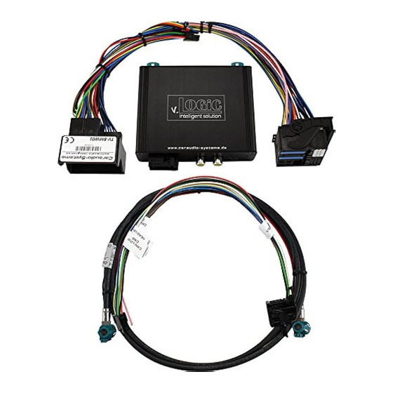
- Page 1 Website: www.incartec.co.uk E-Mail: sales@incartec.co.uk v.LOGiC Intelligent Solution Interface 27-V5-NBT V5-NBT-PNP Compatible for the F-series BMW with navigation system or radio and 6.5”, 7”, 8.8” or 10.25” monitor with 4+2pin HSD2 LVDS connector...
- Page 2 Product features • Own on-screen display and setup • Rear-view camera input • Automatic switching to rear-view camera input on engagement of reverse gear from all operation modes • Front camera input • Manual switching to rear-view camera (only for vehicles with PDC button) •...
-
Page 3: Table Of Contents
Contents 1. Prior to Installation 1.1. Delivery contents 1.2. Check compatibility of vehicle and accessories 1.3. Setting the dip switches of the interface-box V5C-M637 1.4. LED’s of the interface-box V5C-M637 2. Connection schematic 3. Installation 3.1. Connecting interface-box and harnesses 3.1.1. - Page 4 Legal Information By law, watching moving pictures while driving is prohibited, the driver must not be distracted. We do not accept any liability for material damage or personal injury resulting, directly or indirectly, from installation or operation of this product. This product should only be used while standing or to display fixed menus or rear-view-camera video when the vehicle is moving, for example the MP3 menu for DVD upgrades.
-
Page 5: Prior To Installation
1. Prior to installation Read the manual prior to installation. Technical knowledge is necessary for installation. The place of installation must be free of moisture and away from heat sources. 1.1. Delivery contents Take down the SW-version and HW-version of the interface boxes, and store this manual for support purposes. -
Page 6: Setting The Dip Switches Of The Interface-Box V5C-M637
1.2. Setting the dip switches of the interface-box V5C-M637 Dip 1 and 2 on the back of the interface-box V5C-M637 are used to set the monitor type. The default setting is: Vehicle/ navigation Dip 1 Dip 2 Dip 3 6.5“ monitor (ver.1) 6.5“... -
Page 7: Connection Schematic
2. Connection schematic Quadlock male on rear site of the NBT unit TV-BM01 harness +12V switching output Rear gear signal input (+12V) Interface-box V5C-M637 FRONT Rear-view camera V5C-UNI01 harness Front camera +12V switching Quadlock female vehicle harness output... - Page 8 Back of factory monitor LVDS cable CAB-HSD2-RR148 Interface-box V5C-M637 FRONT 4+2Pin HSD2 LVDS female vehicle harness...
-
Page 9: Installation
3. Installation Switch off ignition and disconnect the vehicle’s battery! The interface needs a permanent 12V source. If according to factory rules disconnecting the battery is to be avoided, it is usually sufficient to put the vehicle is sleep-mode. In case the sleep-mode does not work, disconnect the battery with a resistor lead. -
Page 10: Special Case Bmw I3
Connect female 8 pin molex connector of the harness TV-BM01 to the male 8 pin molex connector of the harness TV-BM01. Connect female 12pin AMP connector of the harness TV-BM01 to the front site of the V5C-M637 interface box. 3.1.1. Special case BMW i3 Since the BMW i3 has the head unit under the rear seat, the extension cable V5C-CON300 must be purchased separately. -
Page 11: After-Market Front Camera
3.2.1. After-market front camera 3.2.1.1. Connection to the after-market front camera Interface-box V5C-M637 FRONT V5C-UNI01 harness Front camera +12V camera Power Out 1 (max. 1A) power Connect the video RCA of the after-market front camera to the female RCA connector “FRONT CAM”... -
Page 12: Settings For Connecting An After-Market Front Camera
3.2.1.2. Settings for connecting an after-market front camera You have to configure some settings in the OSD-menus INPUT and OPTION if you want to connect an after-market front camera (Operation of the OSD: see chapter “OSD-Operation”). OSD-menu Menu item Setting Explanation Keine Frontkamera angeschlossen INPUT... -
Page 13: After-Market Rear-View Camera
3.2.2. After-market rear-view camera 3.2.2.1. Connection to the after-market rear-view camera Interface-box V5C-M637 FRONT V5C-UNI01 harness Rear-view TV-BM01 camera Power Out 2 (max. 1A) harness Connect the video RCA of the after-market rear-view camera to the female RCA connector “REAR CAM” of the interface box V5C-M637. The green wire of harness TV-BM01 can be used for +12V electric power supply (max. -
Page 14: Settings For Connecting An After-Market Rear-View Camera
3.2.2.2. Settings for connecting an after-market rear-view camera You have to configure some settings in the OSD-menus INPUT and OPTION if you want to connect an after-market rear-view camera (Operation of the OSD: see chapter “OSD- Operation”). explanation OSD-menu Menu item Setting No rear-view camera connected INPUT... -
Page 15: Configurable Trigger Outputs
3.2.3. Configurable trigger outputs Interface-box V5C-M637 FRONT V5C-UNI01 harness Power Out 1 (max. 1A) TV-BM01 harness Power Out 2 (max. 1A) You can configure the both +12V trigger outputs separately. The pink wire is POWER OUT 1 and the green wire is POWER OUT 2. Note: You can configure the both trigger outputs in the OSD-menu OPTION separately (Operation of the OSD: see chapter “OSD-Operation”). -
Page 16: Interactive Lane Lines
3.3. Interactive lane lines You have to configure some settings in the OSD-menu OPTION if you want to activate interactive lane lines (Operation of the OSD: see chapter “OSD-Operation”). OSD-menu Menu item Setting Explanation RVC LINES LINES Interactive lane lines activated 1/2/3/4/5/6/7/ OPTION CAR TYPE... -
Page 17: Operation
4. Operation 4.1. OSD – On-screen display You can change the basic configurations of the interface in the OSD (on screen display). 4.1.1. OSD – Operation You can control the OSD by iDrive. 4.1.1.1. iDrive High Options Options Back Long press = enter OSD Short press= leave OSD Options... -
Page 18: Idrive Low
4.1.1.2. iDrive Low Options Back Long press = enter OSD Short press= leave OSD 4.1.2. iDrive selection OSD menu „OPTION“ – „IDRIVE“ is for setting the right iDrive control knob. OSD-menu Menu item Setting Explication Vehicles with iDrive Low control knob OPTION IDRIVE Vehicles with iDrive High control knob... -
Page 19: Osd - Additional Setting Options
4.1.3. OSD – Additional setting options The following settings in the OSD-menus OPTION and OSD can be configured over and above the described settings in this manual (Operation of the OSD: see chapter “OSD-Operation”): OSD-menu Menu item Setting Explication POS. X 0-xxx Horizontal position of the OSD POS. -
Page 20: Selecting The Interface As Current Video Source
4.3. Selecting the interface as current video-source Long press MEDIA-button respectively long press AUDIO-button to choose the interface as current Video-source. Short press MEDIA button respectively AUDIO button to switch the video-sources. Each short press will switch to the next enabled input. If all inputs are enabled the order is: →... -
Page 21: Specifications
5. Specifications Operation voltage 10.5 – 14.8V DC Stand-by power drain <0,1mA Operation power drain 190mA Power consumption 2,6W Temperature range -20°C to +80°C Weight (box only) 208g Measurements (box only) B x H x T 103 x 30 x 105 mm 6.
Need help?
Do you have a question about the 27-V5-NBT and is the answer not in the manual?
Questions and answers