Table of Contents
Advertisement
Quick Links
Advertisement
Table of Contents

Related Manuals for Keysight Technologies AC6800 Series


Summary of Contents for Keysight Technologies AC6800 Series
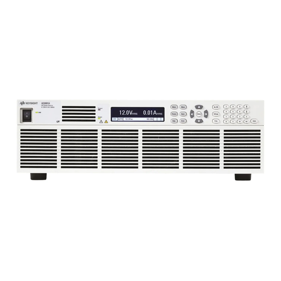
- Page 1 Operating and Service Guide AC6800 Series Basic AC Sources...
-
Page 3: Warranty
Notices Copyright Notice © Keysight Technologies, Inc. 2014-15 Manual Part Number AC6800-90001 Edition Edition 2, November 2015 Published by Keysight Technologies, Inc. 550 Clark Drive, Suite 101 Budd Lake, New Jersey 07828 Warranty THE MATERIAL CONTAINED IN THIS DOCUMENT IS PROVIDED "AS IS," AND IS SUBJECT TO BEING CHANGED, WITHOUT NOTICE, IN FUTURE EDITIONS. -
Page 4: U.s. Government Rights
Software. With respect to any technical data as defined by FAR 2.101, pursuant to FAR 12.211 and 27.404.2 and DFARS 227.7102, the U.S. government acquires no greater than Limited Rights as defined in FAR 27.401 or DFAR 227.7103-5 (c), as applicable in any technical data. Keysight AC6800 Series Operating and Service Guide... -
Page 5: Safety And Regulatory Information
Keysight Technologies assumes no liability of the customer’s failure to comply with the requirements. -
Page 6: General Warnings
L'INTÉRIEUR. CONFIER L'ENTRETIEN DE PERSONNEL QUALIFIÉ. CORRECTEMENT COUPER LE DISJONCTEUR ARMOIRE AVANT DE MANIPULER LES CORDONS D'ALIMENTATION. POUR ÉVITER TOUT CHOC ÉLECTRIQUE, LE CONDUCTEUR DE PROTECTION BORNE DOIT ÊTRE RELIÉE À UNE MASSE ÉLECTRIQUE. Keysight AC6800 Series Operating and Service Guide... - Page 7 The discharge time of the internal capacitor when no load is connected is approximately 0.1 seconds. To prevent the possibility of electric shock, do not touch the output terminal block. Keysight AC6800 Series Operating and Service Guide...
-
Page 8: Heavy Weight
This may cause corrosion of various conductors and bad contacts of connectors inside the instrument leading to malfunction and failure, or in the worst case, a fire. Do not install the product in a dusty location. Accumulation of dust can lead to electric shock or fire. Keysight AC6800 Series Operating and Service Guide... -
Page 9: Installation Warnings
The product may malfunction. Do not install the product on an inclined surface or location subject to vibrations. The product may fall or tip over, causing damage or injuries or both. Keysight AC6800 Series Operating and Service Guide... -
Page 10: Operational Cautions
When transporting the product, be sure to use the original packing materials. Damage may result from vibrations or from the product falling during transportation. Keysight AC6800 Series Operating and Service Guide... -
Page 11: Safety Symbols
This text indicates that the instrument is an Industrial Scientific and Medical Group 1 Class A product (CISPR 11, Clause 4). ICES/NMB-001 This ISM device complies with Canadian ICES-001. Cet appareil ISM est conforme à la norme NMB-001 du Canada. Keysight AC6800 Series Operating and Service Guide... -
Page 12: Software And Documentation Revisions
Product Category: With reference to the equipment types in the WEEE directive Annex 1, this product is classified as “Monitoring and Control instrumentation” product. Do not dispose in domestic household waste. To return unwanted products, contact your local Keysight office, or see about.keysight.com/en/companyinfo/environment/takeback.shtml for more information. Keysight AC6800 Series Operating and Service Guide... -
Page 13: Getting Started
Installing an Optional Interface Board Rack Mounting Connecting the Power Cord Switchboard and Circuit Breaker Requirements Quick Start Interface Connections Remote Interface Configuration Making Output Power Connections Voltage Ranges and Limits Error Checking and Soft Limits Keysight AC6800 Series Operating and Service Guide... -
Page 14: Before Installation Or Use
Observe Environmental Conditions Do not operate the instrument near flammable gases or fumes. The AC6800 Series instruments are Overvoltage Category II instruments that should only be operated in a controlled, indoor environment subject to the following restrictions: – Operating: 0 to 40 °C (32 to 104 °F), 20% to 80% relative humidity, noncondensing –... - Page 15 Allow at least 2 inches (51 mm) of space at the front and back of the unit for air circulation. All dimensions are in mm. Keysight AC6800 Series Operating and Service Guide...
- Page 16 All dimensions are in mm. Keysight AC6800 Series Operating and Service Guide...
-
Page 17: Introduction To The Instrument
Press any key to exit screen saver mode. The status LEDs light to indicate when a protection event has occurred and when the output is on. The display allows you to configure and monitor the instrument. Keysight AC6800 Series Operating and Service Guide... - Page 18 [E] enters the letter E to allow you to enter an exponent to the right of it. [-] backspaces to delete characters. [Enter] enters a value. If you exit a field without pressing [Enter], the value is ignored. Keysight AC6800 Series Operating and Service Guide...
-
Page 19: Front Panel Display At A Glance
Err = an error has occurred (press [Error] to display the error message) Lan = the LAN is connected and has been configured IO = there is activity on one of the remote interfaces Keysight AC6800 Series Operating and Service Guide... - Page 20 For protection from electrical shock, the power cord ground must not be defeated. If only a two- contact electrical outlet is available, connect the instrument’s chassis ground screw (see above) to a good earth ground. AC6801A AC6802A AC6803A AC6804A Keysight AC6800 Series Operating and Service Guide...
-
Page 21: Installing An Optional Interface Board
4. Verify that the switch at the bottom rear of the slot is in the up position. It should only be down during the firm- ware update process. 5. Slide the board all the way into the connector at the back of the slot. 6. Use the slot cover screws to secure the board. Keysight AC6800 Series Operating and Service Guide... -
Page 22: Rack Mounting
Do not block the air intake at the front of the instrument or the exhaust at the rear. To prevent the instrument from falling, install suitable support angles (not included) to support the instrument as shown. Keysight AC6800 Series Operating and Service Guide... - Page 23 Rack Mounting Models AC6801A, AC6802A, and AC6803A Remove the feet from the bottom panel. Using the accompanying M4×10 flat head screws, install the brackets. Using the accompanying dress screws and clip nuts (10-32), mount the instrument in the rack. Keysight AC6800 Series Operating and Service Guide...
- Page 24 Remove the feet from the bottom panel. Using the accompanying M4×10 flat head screws, install the brack- ets. Using the accompanying dress screws and clip nuts (10-32), mount the instrument in the rack. Keysight AC6800 Series Operating and Service Guide...
-
Page 25: Connecting The Power Cord
2. Check that the power switch is turned off. 3. Connect the power cord to the AC input receptacle on the rear panel. 4. Insert the power plug into an outlet. Keysight AC6800 Series Operating and Service Guide... - Page 26 Make sure connections are correct Protective circuits inside the instrument, including input fuses, are connected to match the input terminal polarity. Make sure the colors of the wires connected to the input terminals (L, N, and GND) are correct. Keysight AC6800 Series Operating and Service Guide...
- Page 27 2. Check that the power switch is turned off. 3. Remove the terminal cover attached to the AC INPUT terminal block. 4. Securely connect the power cord to match the L, N, and GND of the AC input terminal block. Keysight AC6800 Series Operating and Service Guide...
- Page 28 5. Re-secure the terminal that you removed above to the terminal block. AC6802A AC6803A AC6804A Keysight AC6800 Series Operating and Service Guide...
- Page 29 Connection must be performed by qualified per- sonnel. 7. Turn off the switchboard. 8. Connect the power cord to match the L, N, and GND of the switchboard. Keysight AC6800 Series Operating and Service Guide...
-
Page 30: Switchboard And Circuit Breaker Requirements
– Apply a label to the switchboard, clearly identifying the disconnecting device and its associated model, as shown below: The tables below provides information about worst case current consumption for all AC6800 Series models for various nominal AC mains voltages. Entries are obtained by dividing the worst case power consumption (in VA) by the nominal mains voltage and rounding to the next highest integer value. - Page 31 Maximum Input VA AC6801A AC6802A AC6803A AC6804A Input VA (Max) 1600 3200 6400 Approximate Maximum Current Line Voltage AC6801A AC6802A AC6803A AC6804A Keysight AC6800 Series Operating and Service Guide...
- Page 32 6, 10, 13, 16, 20, 25, 32, 40, 50, 63, 80, and 100 A NEMA Standard Sizes (also commonly used in Japan) 15, 20, 25, 30, 35, 40, 45, 50, 60, 70, 80, 90, and 100 A Keysight AC6800 Series Operating and Service Guide...
-
Page 33: Quick Start
If a self-test error occurs, a message is displayed on the front panel. For other self-test errors, see Service and Maintenance for instructions. Push the ( O ) side of the POWER switch to turn the instrument off. Keysight AC6800 Series Operating and Service Guide... - Page 34 The exceptions to this rule are when you change the values in [Menu] > Output > Voltage > AC , [Menu] > Output > Voltage > DC , and [Menu] > Output > Frequency . These require you to select the DONE button and press [Enter] . Keysight AC6800 Series Operating and Service Guide...
-
Page 35: Set The Output Voltage
Press On/Off to enable the output. If a load is connected to the output, the front panel display will indicate that it is drawing current. Otherwise, the current reading will be zero. The status indicator shows the output’s status. For a description of the status indicators, refer to Front Panel Display at a Glance. Keysight AC6800 Series Operating and Service Guide... -
Page 36: Use Built-In Help System
Whenever a limit is exceeded or any other invalid configuration is found, the instrument will display a message, including error code information. Press any key other than a navigation arrow to exit Help. Keysight AC6800 Series Operating and Service Guide... -
Page 37: Interface Connections
VISA alias, IDN string, and VISA address. This information is located in the USB folder. 3. You can now use Interactive IO within the Connection Expert to communicate with your instrument, or you can program your instrument using various programming environments. Keysight AC6800 Series Operating and Service Guide... -
Page 38: Lan Connection
3. You can now use Interactive IO within the Connection Expert to communicate with your instrument, or you can program your instrument using various programming environments. You can also use your computer's Web browser to communicate with the instrument. See Using the Web Interface. Keysight AC6800 Series Operating and Service Guide... -
Page 39: Remote Interface Configuration
The instrument ships with an Automation-Ready CD that contains Keysight IO Libraries Suite software, which must be installed to enable remote-interface operations. The CD automatically starts and provides information on installing the software. The CD also includes the Keysight Technologies USB/LAN/GPIB Connectivity Guide , which contains additional information. -
Page 40: Usb Configuration
SCPI Command [Menu] > System > IO > GPIB Not available Use the numeric keypad to enter a value from 0 to 30. Then press [Enter]. This setting is nonvolatile; it will not be changed by power cycling or *RST. Keysight AC6800 Series Operating and Service Guide... -
Page 41: Lan Configuration
By default, DHCP is on, which may enable communication over LAN. The acronym DHCP stands for Dynamic Host Configuration Protocol, a protocol for assigning dynamic IP addresses to networked devices. With dynamic addressing, a device can have a different IP address every time it connects to the network. Keysight AC6800 Series Operating and Service Guide... - Page 42 As you scroll through the list of settings, you will see the following: These may be different from settings requested in the front panel menu due to the configuration of the network, and you cannot edit the settings from this screen. Keysight AC6800 Series Operating and Service Guide...
- Page 43 You can reset the all LAN settings to their factory defaults and restart networking. These default settings are listed under Default Settings. Front Panel SCPI Command [Menu] > System > IO > LAN > Reset Not available [Menu] > System > IO > LAN > Defaults Select Reset to activate the selected LAN settings and restart networking. Keysight AC6800 Series Operating and Service Guide...
-
Page 44: Modifying The Lan Settings
Specifies the IP Address of the default gateway that allows the instrument to communicate with systems not on the local subnet, Gateway as determined by the subnet mask setting. The same numbering notation applies as for the IP Address. A value of 0.0.0.0 indicates that no default gateway is defined. Keysight AC6800 Series Operating and Service Guide... - Page 45 7-character model number (e.g. AC6803A), and serialnumber is the last five characters of the 10-character serial number located on the label on the top of the unit, for example 45678. Keysight AC6800 Series Operating and Service Guide...
- Page 46 (base 8) numbers. For example, "192.168.020.011" is actually equi- valent to decimal "192.168.16.9" because ".020" is interpreted as "16" expressed in octal, and ".011" as "9". To avoid confusion, use decimal values from 0 to 255, without leading zeros. Keysight AC6800 Series Operating and Service Guide...
- Page 47 Check (enable) or uncheck (disable) services as desired. The configurable services include: VXI-11, Telnet, Web control, Sockets, and mDNS. You must enable Web control to remotely control your instrument using the Web page 'Browser Web Control' tab. Keysight AC6800 Series Operating and Service Guide...
-
Page 48: Using The Web Interface
Before touching the output or sense connections or connecting to a device under test, always verify the state of the instrument. Keysight AC6800 Series Operating and Service Guide... - Page 49 5. Click the View and Modify Configuration tab for information about the instrument and its connectivity. Keysight AC6800 Series Operating and Service Guide...
-
Page 50: Using Telnet
IP address, and 5024 is the instrument’s telnet port. You should get a Telnet session box with a title indicating that you are connected to the instrument. Type the SCPI commands at the prompt. Keysight AC6800 Series Operating and Service Guide... -
Page 51: Using Sockets
Using HiSLIP The High-Speed LAN Instrument Protocol (HiSLIP) is a protocol for TCP-based instrument control. It includes conventional test and measurement protocol capabilities with minimal performance impact. For technical details regarding HiSLIP, see www.ivifoundation.org. Keysight AC6800 Series Operating and Service Guide... -
Page 52: Making Output Power Connections
The values vary depending conditions such as the wire covering (insulator) and material (allowable temperature) and whether they are multi-core cables. For cables other than those specified in the table above, please consult with qualified personnel. Keysight AC6800 Series Operating and Service Guide... - Page 53 When shipped from the factory, the terminal cover is attached using the upper holes so that the OUTPUT terminals are not exposed. If you are not using the OUTPUT terminal block, leave the terminal cover attached with the upper holes, as shown below. Keysight AC6800 Series Operating and Service Guide...
- Page 54 In DC mode, L is at positive potential and N is at negative potential when setting the positive value. The opposite is true when setting the negative value. 1. Check that the power switch is turned off. 2. Remove the terminal cover attached to the OUTPUT terminal block. Keysight AC6800 Series Operating and Service Guide...
- Page 55 4. Attach the terminal cover that you removed above using the lower holes. 5. Unlock the ferrite core and open it. Keysight AC6800 Series Operating and Service Guide...
- Page 56 Be sure to turn the switch off before connecting the load to the terminal at the load end of the switch. Do not touch the switch terminal when the output is on. To prevent the possibility of electric shock, do not touch the output terminal block. Keysight AC6800 Series Operating and Service Guide...
-
Page 57: Voltage Ranges And Limits
2.5 A AC6802A 135 V 10 A 270 V AC6803A 135 V 20 A 16 A 270 V 10 A AC6804A 135 V 40 A 32 A 270 V 20 A 16 A Keysight AC6800 Series Operating and Service Guide... - Page 58 0.0 to 275.0 V 270 V 0.0 to 275.0 V 0.0 to 275.0 V DC mode 135 V -389.0 to 194.5 V -194.5 to 389.0 V 270 V -389.0 to +389.0 V -389.0 to +389.0 V Keysight AC6800 Series Operating and Service Guide...
-
Page 59: Error Checking And Soft Limits
Error Checking and Soft Limits The AC6800 Series instruments include error checking measurements and soft limits that prevent unintended operations from being carried. Basic Principles Settings are not automatically changed by either front-panel or SCPI commands, unless the changes are obvious and expected. - Page 60 – If soft limits are enabled, the instrument checks that the setting is within the low and high soft limits. – Settings errors are checked when the user changes the mode setting to Step mode. Keysight AC6800 Series Operating and Service Guide...
- Page 61 TRIGgered values for DC volts are checked for being within range and for meeting the peak voltage con- straint for the currently selected range. These checks occur before the OUTPut:COUPLing change is accepted. Keysight AC6800 Series Operating and Service Guide...
-
Page 63: User Information
Turning Output On and Off Storing and Retrieving Instrument States Configuring Instrument Preferences Calibrating from the Front Panel Configuring Overcurrent Protection Configuring Watchdog Protection Configuring and Clearing Measurements Selecting External Analog Control Viewing Error Messages Keysight AC6800 Series Operating and Service Guide... -
Page 64: Models And Options
Welcome This manual includes user, service, and programming information for the Keysight AC6800 Series of compact AC sources, which can be readily used on the bench or in a test rack. The simple user interface allows you to easily access and view setup and measurement information directly from the front panel or programmatically. -
Page 65: Front Panel Menu Reference
WDog Configures IO watchdog Clear Clears protection conditions and displays output status States Reset Resets instrument to the reset (*RST) state SaveRecall Saves and recalls instrument settings PowerOn Selects the power-on instrument state Keysight AC6800 Series Operating and Service Guide... - Page 66 Save Saves the calibration data Enables/disables the LAN, USB, and GPIB Sanitize Performs NISPOM secure erase of all user data Password Changes the administration password About Displays model, options, serial number, and firmware Keysight AC6800 Series Operating and Service Guide...
-
Page 67: General Front-Panel Organization
Opens the Protect menu (equivalent to [Menu] > Protect). [Back] Backs out of current menu, eventually returning to the Metering Mode display. Not a backspace for numeric entries. [Help] Displays context-sensitive help messages. [Error] Displays messages in ERROR queue. Keysight AC6800 Series Operating and Service Guide... - Page 68 Increment or decrement a Settings field. No effect on numbers entered under the [Menu] key. [Enter] Finishes a numeric entry. You can immediately change values by directly entering numbers into the Settings field. Keysight AC6800 Series Operating and Service Guide...
-
Page 69: Display Layout
Autoranging selected (not available in EXT-AC or EXT-DC mode) Interface Err One or more messages in error queue LAN (displayed) LXI LAN "No fault" LAN (blinking) LXI LAN "Identify" (LAN section blank) LXI LAN "Fault" Remote activity via the LAN connection Keysight AC6800 Series Operating and Service Guide... - Page 70 If AUTO is selected prior to entering either of the external programming modes, the range selected by autoranging is retained until changed by the user. The range field is updated to reflect the actual range when the external programming mode is first entered (if AUTO is selected). Keysight AC6800 Series Operating and Service Guide...
-
Page 71: Selecting The Output Voltage Programming Source And Output Mode
Produce AC output DC mode Produce DC output AC+DC mode Superimpose DC voltage on the AC output EXT-AC mode Output sine waves using external DC signals EXT-DC mode Amplify and output the waveform applied externally Keysight AC6800 Series Operating and Service Guide... -
Page 72: Specifying Output Coupling
+389 V for the high range. Turn the output off to change the output coupling. The instrument performs error checking to ensure that pending active settings remain within range. Front Panel: [Menu] > Output > Coupling SCPI: OUTPut:COUPling AC|DC|ACDC Keysight AC6800 Series Operating and Service Guide... -
Page 73: Programming Ac Output
OUTPut:COUPling AC Voltage Range Front Panel: [Menu] > Output > Range SCPI: [SOURce:]VOLTage:RANGe[:UPPer] 135|270|MINimum|MAXimum The output must be off to change the range settings. The instrument checks to ensure that currently active settings remain within the new range. Keysight AC6800 Series Operating and Service Guide... - Page 74 The frequency limits do not limit output; they prevent unintentional settings. For example, setting a frequency Lo Limit and High Limit of 40 and 45 would prevent you from accidentally entering a frequency of 425 instead of 42.5. SCPI: [SOURce:]FREQuency[:CW] [SOURce:]FREQuency:LIMit[:STATe] [SOURce:]FREQuency:LIMit:LOWer [SOURce:]FREQuency:LIMit:UPPer Keysight AC6800 Series Operating and Service Guide...
-
Page 75: Phase Angle
[Select] or [Enter] . If soft limits are enabled, an error check confirms that the frequency setting is between the low and high limits. VOLTage:RANGe 135 Select the 135 V range. VOLTage:LIMit:UPPer MAX Sets upper limit to maximum, 275 V VOLTage:LIMit:LOWer MIN Sets lower limit to minimum, 0 V Keysight AC6800 Series Operating and Service Guide... - Page 76 In AC+DC mode, the voltage can be specified only when the AC and DC voltage settings are within the voltage limit range and the peak of the AC+DC waveform is between -389 and 389 V. Keysight AC6800 Series Operating and Service Guide...
-
Page 77: Programming Dc Voltage
Programming DC Voltage The AC6800 Series can output DC voltage. When the output is turned on, you cannot change the output mode or voltage range. You must turn the output off first. You can set the voltage regardless of whether the output is on or off. -
Page 78: Setting Limit Values
Whenever the instrument detects peak current exceeding the limit, it raises an OVERLOAD warning, and sets the CL-PEAK bit (bit 10) on the STATus:QUEStionable register. The current limit value of the output current can be specified as shown in the following table. Keysight AC6800 Series Operating and Service Guide... - Page 79 0.1 to 5.25 A 0.2 to 10.5 A 0.4 to 21.0 A 0.8 to 42.0 A DC mode 0.1 to 4.2 A 0.2 to 8.4 A 0.4 to 16.8 A 0.8 to 33.6 A Keysight AC6800 Series Operating and Service Guide...
-
Page 80: Turning Output On And Off
Principle of Output on/off The AC6800 Series instruments do not disconnect output from the internal circuits mechanically using switches and relays. Instead, when the output is turned off, the instruments electrically increase output impedance to limit the output without chattering. -
Page 81: Storing And Retrieving Instrument States
If this happens, turn the output off, recall the memory, and then turn the output back on. SCPI: *RCL *SAV Reset the Instrument to Factory Default Values Select [Menu] > States > Reset > Reset to reset the instrument to its factory defaults. Keysight AC6800 Series Operating and Service Guide... - Page 82 – Auto resume causes the unit to power up in its power-down state. State changes occurring in the last three to four seconds before power-down may not be restored. For this option, the output is always off regardless of whether it was on at power-down. Keysight AC6800 Series Operating and Service Guide...
-
Page 83: Configuring Instrument Preferences
3. Press [Select] to confirm your selection and then press [Meter] to exit. This setting does not change the current meter view; it only changes upon cycling power. For example, the image below shows the starting meter view with Volt, Curr, Power selected. Keysight AC6800 Series Operating and Service Guide... - Page 84 Upper case letters Lower case letters Numeric digits + - ( ) . , <space> Plus, minus, parentheses, period, comma, space To unlock the instrument, press any key other than [Meter] and enter the password. Keysight AC6800 Series Operating and Service Guide...
-
Page 85: Calibrating From The Front Panel
Be sure to read and record the calibration count when you first receive your instrument from the factory. Date Enter the calibration date, which can be up to 15 characters. Save Save the updated calibration constants. For calibration details, see Calibration. Keysight AC6800 Series Operating and Service Guide... -
Page 86: Configuring Overcurrent Protection
To clear an overcurrent protection condition, select [Menu] > Protect > Clear . The current output status condition is displayed to help you ensure that clearing the protection condition is appropriate and likely to produce expected results. Keysight AC6800 Series Operating and Service Guide... -
Page 87: Configuring Watchdog Protection
1 and 3600 seconds (factory default 60). Press [Menu] > Protect > WDog to configure watchdog protection. It is disabled by factory default. SCPI: OUTPut:PROTection:WDOG[:STATe] OUTPut:PROTection:WDOG:DELay Keysight AC6800 Series Operating and Service Guide... -
Page 88: Configuring And Clearing Measurements
Press [Menu] > Measure > Average to specify the number of readings to average for measurements. The drop- down menu allows you to choose 1, 2, 4, 8, or 16. Press [Select] to make your selection. SCPI: SENSe:AVERage Keysight AC6800 Series Operating and Service Guide... - Page 89 In EXT-AC and EXT-DC modes, you may choose the low or high range, but not autoranging. If autoranging is selected before the instrument enters EXT-AC or EXT-DC mode, the present range is retained. Keysight AC6800 Series Operating and Service Guide...
-
Page 90: Viewing Error Messages
The only exception is self-test errors, which cannot be cleared until the underlying condition is corrected. If no errors are in the error queue, "No errors" appears when you press [Error] . SCPI Error Messages for a list of error messages. Keysight AC6800 Series Operating and Service Guide... -
Page 91: Scpi Programming Reference
DISPlay Subsystem FETCh/MEASure Subsystem FREQuency Subsystem HCOPy Subsystem IEEE-488 Common Commands INITiate Subsystem LXI Subsystem OUTPut Subsystem SENSe Subsystem [SOURce:] Subsystem STATus Subsystem SYSTem Subsystem TRIGger Subsystem VOLTage Subsystem Default Settings SCPI Error Messages Keysight AC6800 Series Operating and Service Guide... -
Page 92: Introduction To Scpi
[:STATe], indicate an optional keyword. :OUTPut [:STATe] ON|1|OFF|0 :COUPling AC|DC|ACDC :PROTection :CLEar Keywords Keywords, also referred to as headers, are instructions recognized by the instrument. Common commands are also keywords. Keysight AC6800 Series Operating and Service Guide... -
Page 93: Command Separators And Terminators
Semicolons ( ; ) separate commands within the same subsystem. This lets you send several subsystem commands within the same message string. For example, the following command: FREQuency 100,90,110;MODE FIXed is the same as sending the following commands: FREQuency 100,90,110 FREQuency:MODE FIXed Keysight AC6800 Series Operating and Service Guide... -
Page 94: Syntax Conventions
MIN to set the voltage to its minimum allowable value, or MAX to set it to its maximum allowable value. You can also optionally include the following engineering unit suffixes with numeric parameters: Keysight AC6800 Series Operating and Service Guide... - Page 95 Definite-length block data <Block> allows any type of device-dependent data to be programmed or returned as a series of 8-bit binary data bytes. This is particularly useful for transferring large quantities of data or 8-bit extended ASCII codes. Keysight AC6800 Series Operating and Service Guide...
-
Page 96: Device Clear
333 Query the AC current. MEASure:VOLTage:AC? 333 Query the AC voltage. OUTPut OFF 23 Turn the output OFF. OUTPut ON 11 Turn the output on. VOLTage 18 Set the AC voltage. Using Keysight IO Libraries. Keysight AC6800 Series Operating and Service Guide... -
Page 97: Status Overview
Status Overview This section provides a detailed description of the individual registers and register groups. The status diagram below provides an graphical view of how the status registers and groups are interconnected. Keysight AC6800 Series Operating and Service Guide... -
Page 98: Status Registers
(PTRansition - positive) or from true to false (NTRansition - negative). If both filters are enabled, events will be reported each time the status changes; if both filters are cleared, event reporting is disabled. Keysight AC6800 Series Operating and Service Guide... -
Page 99: Operation Status Group
The instrument is waiting for a TRIGger for the TRANsition trigger subsystem. (not used) (not used) The instrument is in constant voltage (CV) output mode 9-15 512 to 32,768 (not used) (not used) Keysight AC6800 Series Operating and Service Guide... -
Page 100: Questionable Status Group
Power limit (overload state) 12 4096 CL-RMS Current Limit on RMS (overload state) 13 8192 (not used) 0 is returned 14 16384 MEAS-OVLD Measurement overload detected 15 32768 (not used) 0 is returned Keysight AC6800 Series Operating and Service Guide... -
Page 101: Standard Event Status Group
A command syntax error occurred. Error Messages (CME) 64 Reserved 0 is returned 7 128 Power ON (PON) Power has been cycled since the last time the event register was read or cleared. Keysight AC6800 Series Operating and Service Guide... -
Page 102: Status Byte Register
The Output Queue is a first-in, first-out (FIFO) data register that stores instrument-to-controller messages until the controller reads them. Whenever the queue holds messages, it sets the MAV bit (4) of the Status Byte register. Keysight AC6800 Series Operating and Service Guide... -
Page 103: Command Quick Reference
Description [SOURce:]CURRent[:LEVel][:IMMediate][:AMPLitude] <value>|MINimum|MAXimum Sets the immediate AC current limit in amps (rms). [SOURce:]CURRent[:LEVel][:IMMediate][:AMPLitude]? [MINimum|MAXimum] [SOURce:]CURRent:OFFSet[:IMMediate] <value>|MINimum|MAXimum Sets the immediate DC current limit in amps. [SOURce:]CURRent:OFFSet[:IMMediate]? [MINimum|MAXimum] [SOURce:]CURRent:PROTection:STATe ON|1|OFF|0 Enables or disables current protection. [SOURce:]CURRent:PROTection:STATe? Keysight AC6800 Series Operating and Service Guide... -
Page 104: Display Subsystem
Turns the front-panel display on or off. DISPlay[:WINDow][:STATe]? DISPlay[:WINDow]:TEXT "<string>" Displays a text message on the display. DISPlay[:WINDow]:TEXT? DISPlay[:WINDow]:TEXT:CLEar Clears the text message from the display. DISPlay[:WINDow]:VIEW METER_VI|METER_VIP|METER_ALL Selects the parameters to display on the front panel. DISPlay[:WINDow]:VIEW? Keysight AC6800 Series Operating and Service Guide... -
Page 105: Fetch And Measure Subsystems
AC+DC apparent power (VA) MEASure: POWer:ACDC:APParent? FETCh: POWer:ACDC:PFACtor? AC+DC power factor MEASure: POWer:ACDC:PFACtor? FETCh: POWer:ACDC:REACtive? AC+DC reactive power (VAR) MEASure: POWer:ACDC:REACtive? FETCh:VOLTage[:DC]? Average DC voltage (V) MEASure:VOLTage[:DC]? FETCh: VOLTage:AC? AC output voltage (Vrms) MEASure: VOLTage:AC? Keysight AC6800 Series Operating and Service Guide... - Page 106 Sets the transition mode for frequency settings. [SOURce:]FREQuency:MODE? [SOURce:]FREQuency:TRIGgered <value>|MINimum|MAXimum Sets the triggered AC output frequency when frequency [SOURce:]FREQuency:TRIGgered? [MINimum|MAXimum] mode is STEP. HCOPy Subsystem Command/Query Description HCOPy:SDUMp:DATA? Returns the display image in BMP format. Keysight AC6800 Series Operating and Service Guide...
- Page 107 Initiates the TRANsient operation. INITiate:CONTinuous:ACQuire ON|1|OFF|0 Initiates a new measurement and enables or disables "continuous" mode. LXI Subsystem Command/Query Description LXI:IDENtify[:STATe] ON|1|OFF|0 Turns the front-panel LXI identify indicator (blinking "Lan" annunciator) on or off. LXI:IDENtify[:STATe]? Keysight AC6800 Series Operating and Service Guide...
- Page 108 Enables or disables the I/O watchdog timer. OUTPut:PROTection:WDOG[:STATe]? OUTPut:PROTection:WDOG:DELay <value>|MINimum|MAXimum Sets the watchdog delay time. OUTPut:PROTection:WDOG:DELay? [MINimum|MAXimum] SENSe Subsytem Command/Query Description SENSe:AVERage1|2|4|8|16 Sets the averaging count for measurements. SENSe:AVERage? SENSe:CURRent[:PEAK]:HOLD:CLEar Clears the peak held current measurement. Keysight AC6800 Series Operating and Service Guide...
-
Page 109: Status Subsystem
STATus:QUEStionable:ENABle <value> Sets the value of the enable register for the Questionable Status group. STATus:QUEStionable:ENABle? STATus:QUEStionable:NTRansition Sets and queries the value of the (Negative-Transition) and (Positive-Transition) <value> registers. STATus:QUEStionable:NTRansition? STATus:QUEStionable:PTRansition <value> STATus:QUEStionable:PTRansition? Keysight AC6800 Series Operating and Service Guide... -
Page 110: System Subsystem
TRIGger:SYNChronize:PHASe[:ON] <value>|MINimum|MAXimum Sets the phase angle of the output-on phase control in degrees. TRIGger:SYNChronize:PHASe? [MINimum|MAXimum] TRIGger:TRANsient[:IMMediate] Triggers the TRANsient subsystem. TRIGger:TRANsient:SOURce IMMediate|BUS Sets the trigger source for changing the setting value after INIT:TRAN TRIGger:TRANsient:SOURce? Keysight AC6800 Series Operating and Service Guide... -
Page 111: Voltage Subsystem
Sets the triggered DC voltage in VDC. [SOURce:]VOLTage:OFFSet:TRIGgered? [MINimum|MAXimum] [SOURce:]VOLTage:PROGramming:SOURce INTernal|EXTAC|EXTDC Sets the voltage programming source. [SOURce:]VOLTage:PROGramming:SOURce? [SOURce:]VOLTage:RANGe[:UPPer] 135|270|MINimum|MAXimum Sets the voltage range. [SOURce:]VOLTage:RANGe[:UPPer]? [MINimum|MAXimum] [SOURce:]VOLTage:RANGe:AUTO ON|1|OFF|0 Enables or disables voltage autoranging. [SOURce:]VOLTage:RANGe:AUTO? Keysight AC6800 Series Operating and Service Guide... -
Page 112: Abort Subsystem
– If INIT:CONT:ACQ is ON, the ABORt:ACQuire command aborts the measurement but the instrument immediately re-initiates new measurements. ABORt:TRANsient Aborts all TRANsient actions. Parameter Typical Return (none) (none) Abort any TRANsient actions: ABOR:TRAN – This command resets the WTG-tran bit in the Operation Status registers. Keysight AC6800 Series Operating and Service Guide... -
Page 113: Calibrate Subsystem
< value > of 8 will select the 270 V range on the AC6803A, but the 135 V range on the AC6802A. AC6801A AC6802A AC6803A AC6804A 270 V Range 16.0 135 V Range 16.0 32.0 Do not use any unit suffix (such as A) in this command. Keysight AC6800 Series Operating and Service Guide... - Page 114 "14/06/13" is June 14, 2013 or June 13, 2014. The format "2013 Jun 14" avoids that problem. – You may query the value regardless of whether the calibration state is on. Keysight AC6800 Series Operating and Service Guide...
- Page 115 – The voltage full-scale (FS) values are 135 VAC (LOW) and 270 VAC (HIGH) for all models. – The current full-scale (FS) values are shown below. Model LOW HIGH AC6801A 4.0 A 2.0 A AC6802A 8.0 A 4.0 A AC6803A 16.0 A 8.0 A AC6804A 32.0 A 16.0 A Keysight AC6800 Series Operating and Service Guide...
- Page 116 Parameter Typical Return (none) (none) Store calibration constants into nonvolatile memory: CAL:SAVE – The CALibrate:STATe must be ON to execute this command. – This command increments the calibration count by 1. Keysight AC6800 Series Operating and Service Guide...
- Page 117 ON to execute this command. – The CALibrate:VOLTage[:LEVel] command is for AC voltage, and the CALibrate:VOLTage:OFFSet command is for DC voltage. – Do not use unit suffixes, such as V or mV, with this command. Keysight AC6800 Series Operating and Service Guide...
-
Page 118: Current Subsytem
Set the DC current limit to 3 A: CURR:OFFS 3 – Current units (UA, MA, A) are allowed. – Values exceeding the instrument's maximum value will be set to the instrument's maximum value. – The *RST default is the instrument's MAXimum value. Keysight AC6800 Series Operating and Service Guide... - Page 119 Set the meter to display DC measurements: DISP:MET:COUP DC – AC shows pure AC measurement data, DC shows DC measurement data, and ACDC shows all AC and DC measurement data. – The *RST command sets this parameter to ACDC. Keysight AC6800 Series Operating and Service Guide...
- Page 120 – The display text is unaffected by *RCL and *RST`. DISPlay[:WINDow]:TEXT:CLEar Clears the text message from the display. Parameter Typical Return (none) (none) Clear message on display: DISP:TEXT:CLE – The display text is unaffected by *RCL and *RST`. Keysight AC6800 Series Operating and Service Guide...
- Page 121 Selects the parameters to display on the front panel. Parameter Typical Return METER_VI|METER_VP|METER_VIP, *RST METER_VI METER_VI, METER_VIP, or METER_ALL Display voltage and current: DISP:VIEW METER_VI – Examples of the various displays are shown in the table below. METER_VI METER_VIP METER_ALL Keysight AC6800 Series Operating and Service Guide...
- Page 122 Internal data acquisition occurs at 333 ms update intervals, including the aperture as described above, and each completed measurement overwrites the previous data in the buffer. Averaged measurements are a moving average of the latest 2, 4, 8, or 16 measurements. Keysight AC6800 Series Operating and Service Guide...
- Page 123 This command applies to DC, AC+DC, and EXT-DC. Average DC current (A) SENS:AVER Set the averaging period using CURRent:AC? This command applies to AC, AC+DC, EXT-DC, and EXT-AC. AC current (Arms) CURRent:ACDC? This command applies to AC+DC. Current, AC+DC (Arms) Keysight AC6800 Series Operating and Service Guide...
- Page 124 The power factor indicates the efficiency degradation caused by the phase difference between the AC voltage and AC current. POWer:AC:REACtive? This command applies to AC, AC+DC, EXT-DC, and EXT-AC. AC reactive power (VAR) Keysight AC6800 Series Operating and Service Guide...
- Page 125 SENS:AVER Set the averaging period using VOLTage:AC? This command applies to AC, AC+DC, EXT-DC, and EXT-AC. AC output voltage (Vrms) VOLTage:ACDC? This command applies to AC, AC+DC, EXT-DC, and EXT-AC. Voltage, AC+DC (Vrms) Keysight AC6800 Series Operating and Service Guide...
- Page 126 Returns the < measurement > in the form 1.23456E+00. The < measurement > may be any of the queries listed in the table above, such as VOLTage:AC? or VOLTage:ACDC? Examples: – FETC:VOLTage:AC? – MEASure:VOLTage:ACDC? Keysight AC6800 Series Operating and Service Guide...
-
Page 127: Frequency Subsystem
40.0 to 500.0 Hz +1.25000E+02 Default 500 (UPPer) and 40 (LOWer) Set the frequency limits to 125 and 300 Hz: FREQ:LIM:LOW 125 FREQ:LIM:UPP 300 FREQ:LIM:STAT ON – This command applies to AC, AC+DC, EXT-DC, and EXT-AC. Keysight AC6800 Series Operating and Service Guide... - Page 128 Set the triggered frequency to 90 Hz: FREQ:TRIG 90 – This command applies to AC, AC+DC, EXT-DC, and EXT-AC. – The *RST default is 60 Hz. – Frequency suffixes (HZ and KHZ) are allowed. Keysight AC6800 Series Operating and Service Guide...
-
Page 129: Hcopy Subsystem
– The image is a grey-scale Windows .BMP which has fixed 2,110 bytes. The response format is IEEE488.2 definite- length block data -- #N<length><imagebody>, where N is always 4 and <length> is always 2,110, therefore 2,116 bytes in total. Keysight AC6800 Series Operating and Service Guide... -
Page 130: Ieee-488 Common Commands
*ESE. – A *CLS does not clear the enable register, but does clear the event register. – This parameter is not affected by *RST or *RCL. Keysight AC6800 Series Operating and Service Guide... - Page 131 INT;:VOLT:RANG 135;:VOLT:PROG:SOUR INT;:VOLT:IMM 0.0,0.0,137.5;MODE FIX;LIM:STAT 0;:FREQ:IMM 60.0,40.0,500.0;MODE FIX;LIM:STAT 0;:CURR 5.25;:CURR:OFFS 4.20;:CURR:PROT:STAT 1;:SENS:AVER 1;VOLT:EQU 0;:DISP:STAT 1;VIEW METER_VI;MET:COUP ACDC;:TRIG:TRAN:SOUR IMM;:TRIG:ACQ:SOUR IMM;:TRIG:SYNC:SOUR IMM;PHAS:ON 0;:OUTP 0 Return the instrument's learn string: *LRN? – The returned string can be more than 500 characters. Keysight AC6800 Series Operating and Service Guide...
- Page 132 – AC68GPBU (GPIB installed), or AC68ALGU (analog interface board installed). *PSC 0|1 *PSC? Enables (1) or disables (0) the clearing of certain enable registers at power on. These include: – Questionable Data Register (STATus:QUEStionable:ENABle) Keysight AC6800 Series Operating and Service Guide...
- Page 133 It resets the WTG-meas, MEAS-active, WTG-tran, and TRAN-active bits in the Operation Status registers. – This command also aborts TRANsient and ACQuire operations. *SAV <0 to 10> Saves the instrument state to a nonvolatile memory location. Keysight AC6800 Series Operating and Service Guide...
- Page 134 – The Status Byte is a read-only register and the bits are not cleared when it is read. Refer to Status Overview more information. *TRG Trigger command. Applies a software trigger (equivalent to IEEE 488.1 Device Trigger) for both TRANsient and ACQuire trigger groups. Keysight AC6800 Series Operating and Service Guide...
- Page 135 330. In this case, SYST:ERR? will return specific failure messages (at first -330,"Self-test error", and then the self- test error codes). See SCPI Error Messages for more information. – The *TST? command does not execute an actual self-test. Keysight AC6800 Series Operating and Service Guide...
-
Page 136: Initiate Subsystem
– You should normally leave continuous mode off (default). – If the TRANsient operation is already initiated, this command will produce error -213,"Init ignored". – The *RST *RCL commands set this parameter to 0. Keysight AC6800 Series Operating and Service Guide... -
Page 137: Output Subsystem
Default AC Set the output mode to ACDC: OUTP:COUP ACDC – AC (default) produces AC output – DC produces DC output – ACDC combines AC and DC output – The *RST command sets this parameter to AC. Keysight AC6800 Series Operating and Service Guide... - Page 138 – The watchdog timer function is NOT reset by front-panel activity; the output will still shut down after the time period has elapsed. – The *RST command sets this parameter to 0. Keysight AC6800 Series Operating and Service Guide...
- Page 139 Parameter Typical Return 1 to 3600 (seconds) +6.00000E+02 Sets a watchdog delay for 600 seconds: OUTP:PROT:WDOG:DEL 600 – Values (seconds) must be whole numbers. – The *RST command sets this parameter to 60. Keysight AC6800 Series Operating and Service Guide...
-
Page 140: Sense Subsytem
ON. SENSe:CURRent[:PEAK]:HOLD:CLEar Clears the peak held current measurement. Parameter Typical Return (none) (none) Clear the peak current measurement: SENS:CURR:HOLD:CLE – Use FETCh:CURRent:AMPLitude:MAXimum:HOLD? to query the peak held current measurement. Keysight AC6800 Series Operating and Service Guide... -
Page 141: [Source:] Subsystem
[SOURce:] Subsystem Because the SOURce keyword is optional for the [SOURce:]CURRent, [SOURce:]FREQuency, and [SOURce:] VOLTage subsystems, these subsystems are listed without the [SOURce:] keyword. CURRent Subsytem FREQuency Subsystem VOLTage Subsystem Keysight AC6800 Series Operating and Service Guide... - Page 142 – The condition register bits reflect the current condition. If a condition goes away, the corresponding bit is cleared. – A *RST clears this register, other than those bits where the condition still exists after *RST. Keysight AC6800 Series Operating and Service Guide...
- Page 143 – If the same bits in both NTR and PTR registers are set to 0, then no transition of that bit at the Operation Condition register can set the corresponding bit in the Operation Event register. – The value returned is the binary-weighted sum of all bits set in the register. Keysight AC6800 Series Operating and Service Guide...
- Page 144 – The value returned is the binary-weighted sum of all bits set in the register.For example, to enable bit 2 (value 4) and bit 4 (value 16), the corresponding decimal value would be 20 (4 + 16). – *RST does not affect this register. Keysight AC6800 Series Operating and Service Guide...
-
Page 145: Status:questionable:condition
– For example, to enable bit 2 (value 4) and bit 4 (value 16), the corresponding decimal value would be 20 (4 + 16). – A *CLS does not clear the enable register, but does clear the event register. Keysight AC6800 Series Operating and Service Guide... - Page 146 – If the same bits in both NTR and PTR registers are set to 0, then no transition of that bit at the Questionable Condition register can set the corresponding bit in the Questionable Event register. – The value returned is the binary-weighted sum of all bits set in the register. Keysight AC6800 Series Operating and Service Guide...
- Page 147 – The front-panel key click and instrument beeper settings do not affect each other. – A beep is always emitted (even with beep state OFF) when SYSTem:BEEPer is sent. – This parameter is not affected by *RST or *RCL. Keysight AC6800 Series Operating and Service Guide...
- Page 148 – Errors have the following format (the error string may contain up to 255 characters). < error code >,< error string > For a list of error codes and error strings, see SCPI Error Messages. Keysight AC6800 Series Operating and Service Guide...
- Page 149 Enables or disables the screen saver. Parameter Typical Return ON|1|OFF|0 0 (OFF) or 1 (ON) Turn the screen saver off: SYST:SSAV OFF – This parameter is not affected by *RST or *RCL. – This parameter is not affected by power cycling. Keysight AC6800 Series Operating and Service Guide...
-
Page 150: System:version
Returns the version of SCPI that the instrument uses. Parameter Typical Return (none) 1999.0 Return the SCPI version: SYST:VERS? – The query always returns 1999.0 – The SCPI version cannot be determined from front panel. Keysight AC6800 Series Operating and Service Guide... -
Page 151: Trigger Subsystem
Sets the output-on phase control when OUTPut ON is sent. Parameter Typical Return IMMediate|PHASe IMM or PHAS Enable output-on phase control: TRIG:SYNC:SOUR PHASE – This parameter is set to IMMediate at power-on or after *RCL or *RST. Keysight AC6800 Series Operating and Service Guide... - Page 152 BUS to wait for a software trigger (*TRG, TRIG, or TRIG:TRAN). Parameter Typical Return IMMediate|BUS IMM or BUS Set the trigger source to BUS: TRIG:SOUR BUS – This parameter is set to IMMediate at power-on or after *RCL or *RST. Keysight AC6800 Series Operating and Service Guide...
- Page 153 – The allowable range for MINimum and MAXimum varies depending on whether LIM:STAT is ON or OFF. When LIM:STAT is OFF, the MINimum and MAXimum values are simply calculated from the VOLT:RANG and the DC component if it is already set in ACDC mode. Keysight AC6800 Series Operating and Service Guide...
- Page 154 – A SCPI error (-222,"Data out of range") occurs if the entered parameter value is outside the range. – The *RST command sets both limits to 0. Keysight AC6800 Series Operating and Service Guide...
- Page 155 – Error message +160 is generated if the IMMediate voltage is set outside the MIN/MAX limits, and error message +161 is generated if the TRIGgered voltage is set outside the MIN/MAX limits. – Voltage units (MV, V, KV) are supported. – The *RST command sets this parameter to 0. Keysight AC6800 Series Operating and Service Guide...
- Page 156 Sets the trigger transient mode for DC voltage settings. Specifying FIX (default) disables the trigger function; specifying STEP enables it. Parameter Typical Return FIXed|STEP Set the voltage offset mode to FIXed VOLT:OFF:MODE FIXed – The *RST command sets this parameter to FIXed. Keysight AC6800 Series Operating and Service Guide...
- Page 157 Enables or disables voltage autoranging. If this parameter changes, the VOLT:TRIG VOLT:OFFS:TRIG settings are cleared, and all operations are aborted. Parameter Typical Return ON|1|OFF|0 0 (OFF) or 1 (ON) Turn on voltage autoranging: VOLT:RANG:AUTO 1 – The *RST command sets this parameter to OFF. Keysight AC6800 Series Operating and Service Guide...
-
Page 158: Default Settings
(state file value) 135.0 [SOURce:]VOLTage:RANGe:AUTO (state file value) OFF INITiate:CONTinuous:ACQuire TRIGger:TRANsient:SOURce (state file value) BUS TRIGger:SYNChronize:SOURce (state file value) IMMediate TRIGger:SYNChronize:PHASe[:ON] (state file value) 0 TRIGger:ACQuire:SOURce (state file value) BUS DISPlay[:WINDow][:STATe] (state file value) 1 Keysight AC6800 Series Operating and Service Guide... - Page 159 Command *RCL *RST DISPlay[:WINDow]:METer:COUPling (state file value) ACDC SENSe:AVERage (state file value) 1 Keysight AC6800 Series Operating and Service Guide...
-
Page 160: Scpi Error Messages
Undefined header -114 Header suffix out of range -115 Unexpected number of parameters -120 Numeric data error -128 Numeric data not allowed -131 Invalid suffix -138 Suffix not allowed -140 Character data error Keysight AC6800 Series Operating and Service Guide... - Page 161 Remote calibration is inhibited by local operation +131 Operation conflicts with OUTPUT ON state +132 Operation conflicts with protection state +133 Operation conflicts with OUTPUT COUPLE setting +134 Operation conflicts with AUTO RANGE Keysight AC6800 Series Operating and Service Guide...
- Page 162 +309 Cannot initiate, voltage and frequency in fixed mode +901 HW failure (DSP DETECT state) +902 HW failure (DSP VCC state) +903 HW failure (DSP INPUT state) +904 HW failure (DSP Communication Failure) Keysight AC6800 Series Operating and Service Guide...
- Page 163 Enter Calibration Mode DC Voltage Low Range DC Voltage High Range AC Voltage Low Range AC Voltage High Range Current Low Range Current High Range End Calibration Performance Test Records Performance Verification Service Keysight AC6800 Series Operating and Service Guide...
-
Page 164: Calibration Overview
This data is not changed by cycling power or *RST. Keysight Technologies Calibration Services Keysight Technologies offers calibration services using automated calibration systems that enable Keysight to provide calibration at competitive prices. See Contacting Keysight for information on contacting Keysight. -
Page 165: Enter Calibration Mode
Enter Calibration Mode To begin the calibration process, log in using the Admin password. The factory default is no password. Front Panel SCPI Select System > Admin > Login. Then enter the password and press [Select]. CAL:STAT ON[, <password>] Keysight AC6800 Series Operating and Service Guide... - Page 166 Repeat steps 2 and 3 for calibration point 2 (P2). Note that the SCPI command in step 2 will change to CAL:LEV P2, and the front-panel message will read Enter P2 measured data. Select Next or press Back to finish this part of the calibration. Keysight AC6800 Series Operating and Service Guide...
- Page 167 Repeat steps 2 and 3 for calibration point 2 (P2). Note that the SCPI command in step 2 will change to CAL:LEV P2, and the front-panel message will read Enter P2 measured data. Select Next or press Back to finish this part of the calibration. Keysight AC6800 Series Operating and Service Guide...
- Page 168 P2, P3, P4, and P5 in place of P1. Similarly, the front-panel Enter P1 measured data message from step 2 will indicate P2, P3, P4, or P5. Select Next or press Back to finish this part of the calibration. Keysight AC6800 Series Operating and Service Guide...
- Page 169 P2, P3, P4, and P5 in place of P1. Similarly, the front-panel Enter P1 measured data message from step 2 will indicate P2, P3, P4, or P5. Select Next or press Back to finish this part of the calibration. Keysight AC6800 Series Operating and Service Guide...
- Page 170 Enter the computed current from the external DMM meas- CAL:DATA <data> current (I=V/R) and urement and Load resistance and press [Select] or [Enter]. enter the data. Select Next or press Back to finish the calibration step. Keysight AC6800 Series Operating and Service Guide...
-
Page 171: Current Table
Current Table AC6801A AC6802A AC6803A AC6804A Low Range 4.0 A 8.0 A 16.0 A 32.0 A Keysight AC6800 Series Operating and Service Guide... - Page 172 Load resistance and press [Select] or enter the data. [Enter]. Select Next or press Back to finish the calibration step. Current Table, High Range AC6801A AC6802A AC6803A AC6804A High Range 2.0 A 4.0 A 8.0 A 16.0 A Keysight AC6800 Series Operating and Service Guide...
-
Page 173: End Calibration
Front Panel SCPI Enter the calibration [Menu] > System > Admin > Cal > Date CAL:DATE "< date. string>" Enter the calibration date in the Data field. Press [Select] or [Enter] to finish. Save calibration data. [Menu] > System > Admin > Cal > Save CAL:SAVE Log out. [Menu] > System > Admin > Logout CAL:STAT OFF Keysight AC6800 Series Operating and Service Guide... -
Page 174: Performance Verification
Performance Verification This chapter provides performance test verification procedures for the AC6800 Series instruments: – Test equipment required – Front-panel instructions – Performance test records SHOCK HAZARD These tests should only be performed by qualified personnel. During the performance of these tests, hazardous voltages may be present at the output of the unit. -
Page 175: Test Equipment Required
For all tests besides the DC Voltage and Current tests, the DMM should be set to measure AC volts and 100 NPLCs. For the DC voltage tests, the DMM should be set to measure DC volts and 100 NPLC. Keysight AC6800 Series Operating and Service Guide... - Page 176 Constant Voltage Tests If more than one meter or a meter and an oscilloscope are used, connect each to the sense terminals by separate leads to avoid mutual coupling effects. Keysight AC6800 Series Operating and Service Guide...
-
Page 177: Front-Panel Instructions
Program RANGE 270 V, VOLT 270, FREQ 500 Voltage at 270 Vrms CV annunciator on Output current near zero Record voltage readings at DMM and on front panel display. Reading within specified high range limits Keysight AC6800 Series Operating and Service Guide... - Page 178 Disable UUT. Open S1. Turn on the UUT. Program output to RANGE 270 V, VOLT Voltage at 160 Vrms 160, FREQ 60 Output current near zero Record voltage reading of DMM. Keysight AC6800 Series Operating and Service Guide...
- Page 179 10 A for AC6803A 20 A for AC6804A Record voltage reading of DMM. Check test results The difference between the DMM readings in Steps 24 and 26 are within specified load effect limits. Keysight AC6800 Series Operating and Service Guide...
- Page 180 Output Voltage at 160 Vrms, CV annunciator on, output current near: 2.5 A for AC6801A 5 A for AC6802A 10 A for AC6803A 20 A for AC6804A Record DMM reading and calculate rms current. Readings are within specified current limits. Keysight AC6800 Series Operating and Service Guide...
- Page 181 OFFSET 64. output current near: 4 A for AC6801A 8 A for AC6802A 16 A for AC6803A 32 A for AC6804A Record DVM reading and calculate current. Readings within specified DC current readback limits. Keysight AC6800 Series Operating and Service Guide...
- Page 182 Output voltage at 128 VDC, CV annunciator on, output current near: 2 A for AC6801A 4 A for AC6802A 8 A for AC6803A 16 A for AC6804A Record DVM reading and calculate current. Readings within specified dc current readback limits. Keysight AC6800 Series Operating and Service Guide...
-
Page 183: Performance Test Records
Vout + 2.50 VDC DC Current Readback Accuracy Low Range Measurement Iout – 40 mA ______ A Iout + 40 mA High Range Measurement Iout – 20 mA ______ A Iout + 20 mA Keysight AC6800 Series Operating and Service Guide... - Page 184 Vout + 2.50 VDC DC Current Readback Accuracy Low Range Measurement Iout – 80 mA ______ A Iout + 80 mA High Range Measurement Iout – 40 mA ______ A Iout + 40 mA Keysight AC6800 Series Operating and Service Guide...
- Page 185 Vout + 2.50 VDC DC Current Readback Accuracy Low Range Measurement Iout – 160 mA ______ A Iout + 160 mA High Range Measurement Iout – 80 mA ______ A Iout + 80 mA Keysight AC6800 Series Operating and Service Guide...
- Page 186 Vout + 2.50 VDC DC Current Readback Accuracy Low Range Measurement Iout – 320 mA ______ A Iout + 320 mA High Range Measurement Iout – 160 mA ______ A Iout + 160 mA Keysight AC6800 Series Operating and Service Guide...
-
Page 187: Types Of Service Available
Cleaning and Replacing the Filter Types of Service Available If your instrument fails during the warranty period, Keysight Technologies will repair or replace it under the terms of your warranty. After your warranty expires, Keysight offers repair services at competitive prices. You may also consider purchasing a service contract that extends coverage after the standard warranty. -
Page 188: Before Returning The Unit
AC6804A 5067-6052 Rubber foot kit (qty 4) AC6801A, AC6802A, AC6803A 5067-6053 Rubber foot kit (qty 4) AC6804A 5067-6054 Output cover AC6802A 5067-6055 Output cover AC6803A 5067-6056 Output cover AC6804A 5067-6057 Option slot cover Keysight AC6800 Series Operating and Service Guide... -
Page 189: Updating Firmware
3. Also from this page, download the DFU file containing the firmware update onto your PC. 4. Turn off the AC6800 Series instrument and remove the two screws that hold the optional interface board or slot cover in place on the instrument's rear panel. Set the interface board or slot cover aside. - Page 190 12. Exit the DfuSe Demonstration software, turn off the instrument, disconnect the USB cable, return the option slot switch to the up position, and replace the optional card or slot cover, screwing it securely in place. The firm- ware update is complete. Keysight AC6800 Series Operating and Service Guide...
- Page 191 Always remember to log out after completing your administrative tasks if password protection has been enabled. Press [Menu] > System > Admin > Logout > Logout . Change the System Administration Password Select [Menu] > System > Admin > Password to change the instrument's system administration password. The rules for a valid password are described above. Keysight AC6800 Series Operating and Service Guide...
- Page 192 The sanitization procedure is not recommended for use in routine applications because of the possibility of unintended loss of data. Keysight AC6800 Series Operating and Service Guide...
- Page 193 4. Verify that the switch at the bottom rear of the slot is in the up position. It should only be down during the firm- ware update process. 5. Slide the board all the way into the connector at the back of the slot. Keysight AC6800 Series Operating and Service Guide...
- Page 194 Ensure that the instrument is completely dry before turning it on. Keysight AC6800 Series Operating and Service Guide...
-
Page 195: Cleaning And Replacing The Filter
Move the opposite side down in the same manner and detach the front grille. Remove the filter and clean it by rinsing it in water. Ensure that the filter is completely dry and reinstall the filter. Keysight AC6800 Series Operating and Service Guide... - Page 196 Set the plastic finger on the back of the front grille against the slot on the sheet metal. Press the top center portion when it begins to swell outward. Slide the left side of the front grille up and lock it in position. Keysight AC6800 Series Operating and Service Guide...
- Page 197 Slide the right side of the front grille up and lock it in position. If the front grille is not locked, move the bottom of the front grille upward by pressing the concave portion. Keysight AC6800 Series Operating and Service Guide...
-
Page 198: License Files
* the extent permitted by applicable law. You can redistribute it * and/or modify it under the terms of the Do What The ---- You Want * To Public License, Version 2, as published by Sam Hocevar. See http://sam.zoy.org/wtfpl/COPYING for more details. */ Keysight AC6800 Series Operating and Service Guide...
Need help?
Do you have a question about the AC6800 Series and is the answer not in the manual?
Questions and answers