Table of Contents
Advertisement
Advertisement
Table of Contents

Related Manuals for Keysight Technologies AC6801B


Summary of Contents for Keysight Technologies AC6801B
- Page 1 Operating and Service Guide Series Keysight AC6800B Basic AC Sources...
-
Page 2: Table Of Contents
Notices Copyright Notice Manual Part Number Edition Published by Warranty Technology Licenses U.S. Government Rights Safety and Regulatory Information General Information Safety Warnings Product Grounding General Warnings Environmental Warnings Shock Hazard Installation Warnings Heavy Weight Equipment Cautions General Cautions Installation Cautions Operational Cautions Moving Cautions Safety Symbols... - Page 3 Turning the Output On and Off Storing and Retrieving Instrument States Configuring Instrument Preferences Calibrating from the Front Panel Configuring Overcurrent Protection Configuring Watchdog Protection Configuring and Clearing Measurements Using External Analog Control Viewing Error Messages 3 SCPI Programming Reference Introduction to SCPI Status Overview Command Quick Reference ABORt Subsystem...
-
Page 4: Notices
Notices Notices Copyright Notice © Keysight Technologies, Inc. 2017 Manual Part Number AC6800-90901 Edition Edition 1, December 2017 Published by Keysight Technologies, Inc. 550 Clark Drive, Suite 101 Budd Lake, New Jersey 07828 Warranty THE MATERIAL CONTAINED IN THIS DOCUMENT IS PROVIDED "AS IS," AND IS SUBJECT TO BEING CHANGED, WITHOUT NOTICE, IN FUTURE EDITIONS. -
Page 5: U.s. Government Rights
Notices U.S. Government Rights The Software is “commercial computer software,” as defined by Federal Acquisition Regulation (“FAR”) 2.101. Pursuant to FAR 12.212 and 27.405-3 and Department of Defense FAR Supplement (“DFARS”) 227.7202, the U.S. government acquires commercial computer software under the same terms by which the software is customarily provided to the public. -
Page 6: Safety And Regulatory Information
Failure to comply with these precautions or with specific warnings or instructions elsewhere in this manual violates safety standards of design, manufacture, and intended use of the instrument. Keysight Technologies assumes no liability of the customer’s failure to comply with the requirements. -
Page 7: General Warnings
Safety and Regulatory Information General Warnings Do not use this product in any manner not specified by the manufacturer. The protective features of this product may be impaired if it is used in a manner not specified in the operation instructions. Instruments that appear damaged or defective should be made inoperative and secured against unintended operation until they can be repaired by qualified service personnel. -
Page 8: Shock Hazard
Safety and Regulatory Information Shock Hazard Before making any load or sense connections be sure to turn the POWER switch off and remove the power plug from an outlet or turn off the circuit breaker of switchboard. When the power switch is turned off while the output is on, residual voltage still remains at the output terminals. -
Page 9: Installation Warnings
Safety and Regulatory Information Installation Warnings Have a qualified engineer connect the power cord to the switchboard. Protective circuits inside the instrument, including input fuses, are connected to match the input terminal polarity. Make sure the colors of the wires connected to the input terminals (L, N, ... -
Page 10: Equipment Cautions
Safety and Regulatory Information Equipment Cautions A CAUTION notice denotes a hazard. It calls attention to an operating procedure, practice, or the like that, if not correctly performed or adhered to, could result in damage to the product or loss of important data. -
Page 11: Safety Symbols
Safety and Regulatory Information Safety Symbols Direct current Alternating current Frame or chassis terminal Standby supply. Unit is not completely disconnected from AC mains when switch is off. Caution, risk of electric shock Caution, refer to accompanying documents Earth ground terminal The CE mark is a registered trademark of the European Community. - Page 12 Safety and Regulatory Information Waste Electrical and Electronic Equipment (WEEE) This product complies with the WEEE Directive) marketing requirement. The affixed product label (see below) indicates that you must not discard this electrical/electronic product in domestic household waste. Product Category: With reference to the equipment types in the WEEE directive Annex 1, this product is classified as “Monitoring and Control instrumentation”...
-
Page 13: Getting Started
Keysight AC6800B Series Operating and Service Guide 1 Getting Started Before Installation or Use Introduction to the Instrument Instrument Ratings Installing an Optional Interface Board Rack Mounting Connecting the Power Cord Switchboard and Circuit Breaker Requirements Quick Start Interface Connections Remote Interface Configuration Making Output Power Connections Voltage Ranges and Limits... -
Page 14: Before Installation Or Use
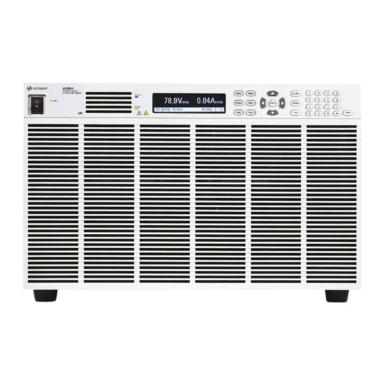
Check for Items Supplied Verify that you received the following items. AC6800B Series AC Source Line cord (AC6801B only) AC input cover (AC6803B and AC6804B only) Ferrite core and cable tie (two supplied with AC6803B) CD - IO Libraries Media Suite... - Page 15 Allow at least 8 inches (20 cm) of space at the front and back of the unit for air circulation. All dimensions are in mm. AC6801B Keysight AC6800B Series Operating and Service Guide...
- Page 16 1 Getting Started AC6802B Keysight AC6800B Series Operating and Service Guide...
- Page 17 1 Getting Started AC6803B Keysight AC6800B Series Operating and Service Guide...
- Page 18 1 Getting Started AC6804B Keysight AC6800B Series Operating and Service Guide...
-
Page 19: Introduction To The Instrument
1 Getting Started Introduction to the Instrument Front Panel at a Glance Front Panel Display at a Glance Rear Panel at a Glance Instrument Ratings Front Panel at a Glance The following table lists the main parts of the front panel, from left to right: The [Power] switch turns the unit on or off. - Page 20 1 Getting Started [Meter] returns the display to metering mode. Pressing it repeatedly cycles the display through all three formats (METER_VI, METER_VIP, and METER_ALL). [Menu] opens the top level of the command menu. Pressing it a second time returns to the metering mode display. [Protect] brings the user to the Protect menu.
- Page 21 1 Getting Started Front Panel Display at a Glance Metering field Shows the measured output. Status field Displays the instrument status: OFF = the output is off. CV = the output is in constant voltage mode. OC = the output is disabled by the overcurrent protection. OT = the overtemperature protection has tripped.
- Page 22 Rear Panel at a Glance For protection from electrical shock, the power cord ground must not be defeated. If only a two-contact electrical outlet is available, connect the instrument’s chassis ground screw (see above) to a good earth ground. AC6801B AC6802B AC6803B AC6804B...
-
Page 23: Instrument Ratings
1 Getting Started Instrument Ratings AC6801B AC6802B AC6803B AC6804B Output Rating for AC mode (155 V/310 V range) Rated voltage range 1 to 155 Vrms/2 to 310 Vrms Maximum rms current 5 A/2.5 A 10 A/5 A 20 A/10 A 40 A/20 A... -
Page 24: Installing An Optional Interface Board
1 Getting Started Installing an Optional Interface Board The rear-panel slot can hold either the GPIB interface board (option AC68GPBU) or the analog output interface board (option AC68BALGU). Consult with your Keysight sales representative or distributor for information regarding the availability of option AC68BALGU. To install a board: 1. -
Page 25: Rack Mounting
1 Getting Started Rack Mounting This section requires option AC68BRAC3 (for models AC6801B, AC6802B, and AC6803B) or AC68BRAC6 (for model AC6804B). This section contains instructions for installing the instruments in a 19-inch EIA rack. Verification of Option Kit Verify that you received the following items. If anything is missing, please... - Page 26 1 Getting Started Rack Mounting Models AC6801B, AC6802B, and AC6803B Remove the feet from the bottom panel. Using the accompanying M4×10 flat head screws, install the brack- ets. Using the accompanying dress screws and clip nuts (10-32), mount the instrument in the rack.
- Page 27 1 Getting Started Rack Mounting Model AC6804B Remove the feet from the bottom panel. Using the accompanying M4×10 flat head screws, install the brackets. Using the accompanying dress screws and clip nuts (10-32), mount the instrument in the rack. Keysight AC6800B Series Operating and Service Guide...
-
Page 28: Connecting The Power Cord
The power cord used with the product varies depending on the model. This product complies with IEC Overvoltage Category II (energy-consuming equipment supplied from a fixed installation). The AC6801B line cord has a molded plug on both ends. The AC6802B is a single-phase, cord-connected device that requires a plug and cord set. - Page 29 1 Getting Started AC6802B, AC6803B, and AC6804B The AC6802B requires use of a flexible plug and cord set which must be supplied by the user. The line cord must have a plug on the utility side; you cannot hard-wire the instrument to utility mains. The AC6803B and AC6804B instruments may be connected either by a flexible plug and cord set supplied by the user or may, alternatively, be hard wired to the utility mains.
- Page 30 1 Getting Started 4. Securely connect the power cord to match the L (line), N (neutral), and GND (ground) of the AC Input terminal block. The protective earth terminal (ground) requires an extra length of wire compared to the Line and Neutral wires. Always connect the ground wire first. 5.
- Page 31 1 Getting Started AC6803B Install one of the two ferrite cores shipped with the unit close to the power cord strain relief as shown: AC6804B Attach crimp terminals to the switchboard end of the power cord (the end without terminals). For termination, attach a crimp-style terminal to each wire that meets the terminal screws of the switchboard to be connected, and then securely connect the wires to the terminal screws.
-
Page 32: Switchboard And Circuit Breaker Requirements
1 Getting Started Switchboard and Circuit Breaker Requirements Turn off the switchboard circuit breaker to disconnect the instrument from the AC line in an emergency. The breaker must be suitably located and easily reached, and it must be marked as the disconnecting device for the equipment. This section is provided for guidance only;... - Page 33 (100, 200, and 230 V) assumes 100% utilization. By comparing the table above with the table below, it may be seen that for the AC6801B and AC6802B models, the smallest standard size breaker affords more than enough capability to supply the device. The AC6803B and AC6804B products drawn higher currents and therefore are more likely to require higher breaker current ratings and dedicated circuits.
- Page 34 1 Getting Started Line Voltage AC6801B AC6802B AC6803B AC6804B IEC 60898-1 and European Standard EN 60898-1 Standard Sizes 6, 10, 13, 16, 20, 25, 32, 40, 50, 63, 80, and 100 A NEMA Standard Sizes (also commonly used in Japan) 15, 20, 25, 30, 35, 40, 45, 50, 60, 70, 80, 90, and 100 A...
-
Page 35: Quick Start
1 Getting Started Quick Start Turn the Unit On and Off Use the Menu System Enter Numeric and Alphanumeric Values Set the Output Voltage Set the Output Current Limit Enable the Output Use Built-in Help System Turn the Unit On and Off To turn the instrument on: 1. - Page 36 1 Getting Started Use the Menu System Press the [Menu] key to access the top level of the command menu, shown below. The first line displays the menu path (Menu:\), and the second line indicates the items that are available at the present menu level (Output, Measure, and so on). The third line indicates the items under the highlighted function in the second line.
- Page 37 1 Getting Started Set the Output Voltage Method 1 Press [Menu] > Output > Voltage, then choose AC or DC. Use the left and right navigation keys to navigate to the setting to be changed. In the following display, the voltage setting is selected. Enter the desired setting using the numeric keypad.
- Page 38 1 Getting Started Use Built-in Help System View help Press [Help] to view help at any time. If you are at a menu screen, you will get help for navigating through the menus, and if you are at a screen that allows you to view or edit settings, you will get help pertaining to those particular settings.
-
Page 39: Interface Connections
1 Getting Started Interface Connections GPIB Connection USB Connection LAN Connection This section describes how to connect to the instrument's various communication interfaces. For additional information, refer to Remote Interface Configuration. To begin, please install the Keysight IO Libraries Suite from the Keysight Automation-Ready CD that is shipped with your instrument. - Page 40 1 Getting Started the display when the LAN port has been configured. 2. Use the Connection Expert utility of the Keysight IO Libraries Suite to add the instrument and verify a connection. To add the instrument, you can request the Connection Expert to discover the instru- ment.
-
Page 41: Remote Interface Configuration
The instrument ships with an Automation-Ready CD that contains Keysight IO Libraries Suite software, which must be installed to enable remote-interface operations. The CD automatically starts and provides information on installing the software. The CD also includes the Keysight Technologies USB/LAN/GPIB Connectivity Guide, which contains additional information. - Page 42 The instrument complies with USB Specification 2.0, USBTMC Specification 1.0, and USBTMC- USB488 Specification 1.0. The maximum data rate is 12.5 Mbps, the vendor ID is 0x0957, and the product ID values are shown in the table below. Model Product ID AC6801B 0x1A02 AC6802B 0x1B02 AC6803B...
- Page 43 1 Getting Started After changing LAN settings, you must save the changes by pressing System > IO > LAN > Apply. Saving changes restarts the LAN connection with the new settings. LAN settings are nonvolatile; they will not be changed by power cycling or *RST. To cancel your changes, select System > IO > LAN > Cancel. By default, DHCP is on, which may enable communication over LAN.
- Page 44 1 Getting Started Resetting the LAN You can perform an LXI reset of the LAN settings. This resets DHCP (ON), DNS server address configuration, mDNS state (ON), and Web password (blank). These settings are optimized for connecting your instrument to a site network. They should also work well for other network configurations.
- Page 45 1 Getting Started Auto Automatically configures instrument addressing. When selected, the instrument will first try to obtain an IP address from a DHCP server. If a DHCP server is found, the DHCP server will assign an IP address, Subnet Mask, and Default Gateway to the instrument.
- Page 46 1 Getting Started DNS Server and WINS Server DNS is an internet service that translates domain names into IP addresses. It is also needed for the instrument to find and display its host name assigned by the network. Normally, DHCP discovers the DNS address information;...
- Page 47 1 Getting Started Each instrument ships with a default service name with the format: Keysight-modelnumber- description-serialnumber, where modelnumber is the unit’s 7-character model number (e.g. AC6803B), description is the description, and serialnumber is the serial number on the instrument's label. Services This enables and disables LAN services.
- Page 48 1 Getting Started 1. Open your computer's Web browser. 2. Enter the instrument’s host name or IP address into the browser’s Address field. The following wel- come page will appear. Keysight AC6800B Series Operating and Service Guide...
- Page 49 1 Getting Started 3. Click on the Browser Web Control tab in the navigation bar on the left to begin controlling your instru- ment. Should network communication issues occur, the instrument settings shown in the Browser Web Control page may not represent the actual state of the instrument. This may result in unexpected hazardous voltages on the output and sense connections that could result in personal injury, death, or damage to a device under test.
- Page 50 1 Getting Started If desired, you can control access to the Web interface using password protection. As shipped from the factory, no password is set. To set a password, click View & Modify Configuration. Refer to the online help for details. Using Telnet In a DOS command window, enter the command telnet host name 5024 where host name is the instrument's host name or IP address, and 5024 is the instrument’s telnet port.
-
Page 51: Making Output Power Connections
1 Getting Started Making Output Power Connections Preparation Connecting the Load Cables Connecting the Remote Sense Wires Preparation Wire Requirements For connecting the load, use noncombustible load wires rated to carry the maximum rated output current. Nominal Cross-Sectional Area (mm ) AWG Reference cross-sectional area (mm²) Allowable Current (A) (Ta=30 °C) 0.82 1.25 1.31... - Page 52 1 Getting Started Connecting the Load Cables Possible Electric Shock Before making any load or sense connections be sure to turn the POWER switch off and remove the power plug from an outlet or turn off the circuit breaker of switchboard. When the power switch is turned off while the output is on, residual voltage still remains at the output terminals.
- Page 53 1 Getting Started 1. Check that the power switch is turned off. 2. Remove the terminal cover attached to the OUTPUT terminal block. 3. Securely connect the load wires to the OUTPUT terminal block. The length of the load cables should be less than 30 meters.
- Page 54 1 Getting Started 5. Unlock the ferrite core and open it. 6. Close the ferrite core. Avoid catching the wire on the ferrite core. Attach the ferrite core within 10 cm from the OUTPUT terminal block (as indicated by the arrows below). Lock the ferrite core securely in place.
- Page 55 1 Getting Started Remote sensing compensates for voltage drops in long load cables by monitoring the output voltage directly at the load, The sensing function can compensate up to 1 Vrms for a single load line. Always select a load wire that is thick enough to prevent the voltage drop in the wire from exceeding the compensation voltage.
- Page 56 1 Getting Started 5. Install the sense plug and the sense connector cover. Remote Sense Operation Turn the sensing function on and off using the SENSE switch located below the LAN connector on the rear panel. Make sure the output is off when flipping the sense switch. Flipping the SENSE switch up (RMT) turns the remote sense function on.
-
Page 57: Voltage Ranges And Limits
0.0 to 157.5 V -222.5 to +222.5 V 310 V 0.0 to 315.0 V -445.0 to +445.0 V Voltage range Maximum Output Current AC Mode DC Mode or AC+DC Mode AC6801B 155 V 310 V 2.5 A AC6802B 155 V 10 A... - Page 58 1 Getting Started The following chart shows the maximum current output by voltage. Upper and lower voltage limits The voltage limit ranges are shown below. Set the limits so that the upper limit is greater than or equal to the lower limit. Output mode Voltage Range Lower Limit Upper Limit AC Mode...
-
Page 59: Error Checking And Soft Limits
1 Getting Started Error Checking and Soft Limits The AC6800 Series instruments include error checking measurements and soft limits that prevent unintended operations from being carried. Basic Principles Settings are not automatically changed by either front-panel or SCPI commands, unless the changes are obvious and expected. - Page 60 1 Getting Started Range Error Checking The instrument uses the following method to check for range errors. 1. Active settings are limited by MINimum and MAXimum values. The active settings considered are only those relevant to the output coupling. In AC+DC coupling, both DC and AC voltage settings are act- ive, so range checking is applied to the peak absolute value of the combined waveforms.
- Page 61 1 Getting Started Output Coupling Error Checking Changing output coupling from AC+DC requires no error check. Otherwise, changing to DC coupling runs the Volts DC settings error check, and changing to AC or AC+DC runs the Volts AC settings error check. Coupled Parameter Error Checking Inactive parameters generally are not checked for being within range or compliant with soft limits even if soft limits are active for the parameter type.
-
Page 63: User Information
Keysight AC6800B Series Operating and Service Guide 2 User Information Welcome Front Panel Menu Reference General Front-Panel Organization Selecting the Output Voltage Programming Source and Output Mode Specifying Output Coupling Programming AC Output Programming DC Voltage Setting Limit Values Turning the Output On and Off Storing and Retrieving Instrument States Configuring Instrument Preferences Calibrating from the Front Panel... -
Page 64: Welcome
4,000 The AC6800B Series has four options, described below. Option Description AC68BRAC3 Rack mounting kit for AC6801B, AC6802B, and AC6803B AC68BRAC6 Rack mounting kit for AC6804B AC68GPBU GPIB interface board AC68BALGU Analog interface board - controls the output with external analog signals in two modes: EXT-AC: The AC output voltage varies according to the input DC signal. - Page 65 2 User Information If you have questions about your shipment, or if you need information about warranty, service, or technical support, contact Keysight Technologies. Contacting Keysight Technologies United States: (800) 829-4444 Europe: 31 20 547 2111 Japan: 0120-421-345 www.keysight.com/find/assist to contact Keysight worldwide.
-
Page 66: Front Panel Menu Reference
2 User Information Front Panel Menu Reference This is an overview of the front-panel menus. Press [Menu] to access the front-panel menus. For a menu navigation tutorial, see Use the Menu System. Level 1 Level 2 Levels 3&4 Description Output Voltage Sets output voltage and limits Sets AC voltage and limits Sets DC voltage and limits... - Page 67 2 User Information Level 1 Level 2 Levels 3&4 Description System IO Configures LAN, USB, and optional GPIB Configures LAN IO Settings View the currently active network settings Modify Modify the network configuration (IP, Name, DNS, WINS, mDNS, Services) Apply Applies the configuration changes and restarts unit Cancel Cancels the configuration changes Reset Performs an LXI LCI reset of LAN settings and restarts Defaults Resets LAN settings to factory defaults and restarts...
-
Page 68: General Front-Panel Organization
2 User Information General Front-Panel Organization Keypad Layout Item Description Mains Switch Rocker switch for turning the instrument on (1) and off (0). The LINE indicator turns green when power is on. Display 64 × 256 monochrome dot matrix display Status LEDs PROTECT Lights in red when a protection feature has been activated OUTPUT Lights in green when output is ON... - Page 69 2 User Information Item Description Settings Keys [On/Off] Toggles the output ON or OFF. [Voltage] Opens the VAC or VDC (depending on output coupling mode) Settings fields in the Metering Mode display (See Section 6). [Freq] Opens the Frequency Settings field in the Metering Mode display. Numeric Entry [0] to [9] Enters a numeric digit.
- Page 70 2 User Information Field Display Description Status Output is disabled Constant voltage mode CLrms Current limit mode Power limit mode Overvoltage protection; output OFF Overcurrent protection (rms/avg); output OFF OCPK Overcurrent protection (peak); output OFF Overpower protection; output OFF Overtemperature protection; output OFF Low voltage protection (AC input);...
-
Page 71: Selecting The Output Voltage Programming Source And Output Mode
2 User Information Selecting the Output Voltage Programming Source and Output Mode Select the Output Voltage Programming Source The EXT-AC and EXT-DC modes require the optional analog interface board (option AC68BALGU). You cannot use the analog output interface board with the GPIB interface because both boards use the same slot. -
Page 72: Specifying Output Coupling
2 User Information Specifying Output Coupling The instruments support three types of output coupling: Coupling Description AC+DC AC output with positive or negative DC offset AC output Positive or negative (bipolar) DC output In AC+DC mode the combined peak voltage must be between -222.5 and +222.5 V for the low range or -445 and +445 V for the high range. -
Page 73: Programming Ac Output
2 User Information Programming AC Output You can program the voltage, frequency, frequency limits, and starting phase angle of the AC output. Before programming the output, select the appropriate output mode and voltage range. Output Mode Front Panel: [Menu] > Output > Voltage > AC SCPI: OUTPut:COUPling AC Voltage Range Front Panel: ... - Page 74 2 User Information Voltage Front Panel: Press [Voltage], enter the desired value with the numeric keypad, and press [Enter]. You may also change the voltage and voltage limits by pressing [Menu] > Output > Voltage > AC. To specify the voltage limits, check the Enable Limits box to enable the Lo Limit and Hi Limit. The voltage limits do not limit output;...
- Page 75 2 User Information Frequency You can set the output frequency from 40 to 500 Hz for AC mode and AC+DC mode, regardless of whether the output is on. Set the limits so that the upper limit is greater than or equal to the lower limit.
- Page 76 2 User Information Phase Angle To select the output-on starting phase for AC output at turn-on, select [Menu] > Output > Phase. Select the Synchronize checkbox to enable output phase control, otherwise the turn-on phase will be random. The output always turns off at the zero-crossing phase to ensure the instrument's output capacitor discharges when there is no load.
- Page 77 2 User Information VOLTage:RANGe 155 Select the 155 V range. VOLTage:LIMit:UPPer MAX Sets upper limit to maximum, 315 V VOLTage:LIMit:LOWer MIN Sets lower limit to minimum, 0 V VOLTage 120 Sets voltage to 120 V FREQuency:LIMit:UPPer MAX Sets upper limit to maximum, 500 Hz FREQuency:LIMit:LOWer MIN Sets lower limit to minimum, 40 Hz FREQuency 70...
-
Page 78: Programming Dc Voltage
2 User Information Programming DC Voltage The AC6800B Series can output DC voltage. When the output is turned on, you cannot change the output mode or voltage range. You must turn the output off first. You can set the voltage regardless of whether the output is on or off. -
Page 79: Setting Limit Values
2 User Information Setting Limit Values The limit function limits the instrument's output to prevent damage to the load. You should specify limits before applying output to the load, but you can set limits with the OUTPUT on. Note that the limit value takes precedence over the setting value for voltage and frequency. - Page 80 2 User Information Limit Output mode AC6801B AC6802B AC6803B AC6804B AC Mode 0.1 to 5.25 A 0.2 to 10.5 A 0.4 to 21.0 A 0.8 to 42.0 A DC mode 0.1 to 4.2 A 0.2 to 8.4 A 0.4 to 16.8 A 0.8 to 33.6 A...
-
Page 81: Turning The Output On And Off
The AC6800B Series instruments do not disconnect output from the internal circuits mechanically using switches and relays. Instead, when the output is turned off, the instruments electrically increase output impedance to limit the output without chattering. The resistance in the high-impedance condition is shown below. Voltage Range AC6801B AC6802B AC6803B AC6804B 155 V approx. -
Page 82: Storing And Retrieving Instrument States
2 User Information Storing and Retrieving Instrument States State Storage The instrument stores the parameters shown in the table below at five-second intervals. To ensure that settings changes are saved before power-down, wait at least five seconds after changing a setting before turning the instrument off. Otherwise, the last settings may not be stored. The instrument's output is always off at power up. - Page 83 2 User Information Reset the Instrument to Factory Default Values Select [Menu] > States > Reset > Reset to reset the instrument to its factory defaults. SCPI: *RST Configure the Instrument's Power-on State Select [Menu] > States > PowerOn to configure the instrument's power-on state. Reset state (*RST) is the factory default. Recall state 0 will recall the state saved in location 0.
-
Page 84: Configuring Instrument Preferences
2 User Information Configuring Instrument Preferences Press [Menu] > System > Preferences to configure the display and to lock and unlock the instrument. Configure the Screen Saver Press [Menu] > System > Preferences > Display > Saver to configure the screen saver. Screen saver – enables the screen saver function. Saver delay – specifies the time in minutes between the last time any communication occurs with the instrument or a key is pressed until the screen saver goes into effect. - Page 85 2 User Information Lock and Unlock the Front Panel Be certain that you enter the password carefully and remember it. You cannot clear the password by cycling instrument power. Press [Menu] > System > Preferences > Lock to lock the front panel. There is no factory default password. The password must be 4 to 15 characters long and may include any of these characters: Characters Description...
-
Page 86: Calibrating From The Front Panel
2 User Information Calibrating from the Front Panel Log in with the administration password at [Menu] > System > Admin > Login and then use [Menu] > System > Admin > Cal to enter the calibration menu, shown below. Remember to log out with [Menu] > System > Admin > Logout after you have completed your calibration tasks. Node Meaning Calibrate DC voltage programming and measurement (low and high ranges). -
Page 87: Configuring Overcurrent Protection
Current limit settings vary by model, as shown below. The AC limits apply in AC and AC+DC output coupling modes. Model Number AC Limit Range (Arms) DC Limit Range (Arms) AC6801B 0.1 to 5.3 0.1 to 4.2 AC6802B 0.2 to 10.5... -
Page 88: Configuring Watchdog Protection
2 User Information Configuring Watchdog Protection The watchdog protection feature places the output in protection mode if a SCPI command or query is not received within the specified delay period, which may be set between 1 and 3600 seconds (factory default 60). Press [Menu] > Protect > WDog to configure watchdog protection. -
Page 89: Configuring And Clearing Measurements
2 User Information Configuring and Clearing Measurements The Measure menu [Menu] > Measure allows you to view and clear the current peak hold value, configure the measurement coupling, and specify the number of readings to average. View and Clear IpkHold Press [Menu] > Measure > IpkHold to display the current peak hold value. Higher peak values overwrite previously measured lower values until power is cycled or until IpkHold is reset using Clear. -
Page 90: Using External Analog Control
2 User Information Using External Analog Control EXT-AC Mode EXT-DC Mode The analog interface board (option AC68BALGU) supports two external analog programming methods, EXT-AC and EXT-DC. In EXT-AC mode the voltage of the output AC waveform (sine wave) is varied according to the input DC signal. In EXT-DC mode the input waveform is simplify amplified and output. You cannot set the voltage limit when the AC source is being controlled using external analog signals. - Page 91 2 User Information EXT-AC Mode In EXT-AC mode, the unit outputs AC voltage ranging from 0 V to 155 V (when the 155 V range is selected) or 0 V to 310 V (when the 310 V range is selected) with respect to a DC input signal ranging from 0 V to ±10 V.
- Page 92 2 User Information Adjusting the Offset You can fine-adjust the offset by turning the OFFSET adjustment using a Phillips screwdriver. Adjust the offset so that the output voltage is minimum with the input BNC connector shorted. Adjusting the Gain You can fine-adjust the gain by turning the GAIN adjustment using a Phillips screwdriver . Adjust the gain so that the output voltage is 155 Vac (in the 155 V range) when 10 VDC is applied to the input BNC connector.
- Page 93 2 User Information Step 8. Apply the external signal to the INPUT terminal. Step 9. Turn the output on. The analog output voltage is displayed on the Meter menu. Adjusting the Offset You can fine-adjust the offset by turning the OFFSET adjustment using a Phillips screwdriver. Adjust the offset so that the output voltage is as close to 0 V (DC) as possible with the ATT switch turned off and the input BNC connector shorted.
-
Page 94: Viewing Error Messages
2 User Information Viewing Error Messages The Err annunciator in the lower right corner indicates messages in the error queue. Press [Error] to view errors in the error queue. You can also use the SCPI SYSTem:ERRor? query to view error messages. Errors in the error queue are stored and retrieved on a first-in, first-out basis. -
Page 95: Scpi Programming Reference
Keysight AC6800B Series Operating and Service Guide 3 SCPI Programming Reference Introduction to SCPI Status System Overview Command Quick Reference Commands by Subystem ABORt Subsystem CALibrate Subsystem CURRent Subsystem DISPlay Subsystem FETCh/MEASure Subsystem FREQuency Subsystem HCOPy Subsystem IEEE-488 Common Commands INITiate Subsystem LXI Subsystem OUTPut Subsystem... -
Page 96: Introduction To Scpi
3 SCPI Programming Reference Introduction to SCPI Introduction Keywords Queries Command Separators and Terminators Syntax Conventions Parameter Types Device Clear Typical Command Processing Times Introduction This manual describes instrument programming using Standard Commands for Programmable Instruments (SCPI) over LAN, USB, and GPIB (optional). Select the interface type from the front panel, and be sure to understand the SCPI syntax and functions before you send SCPI commands and queries. - Page 97 3 SCPI Programming Reference Keywords Keywords, also referred to as headers, are instructions recognized by the instrument. Common commands are also keywords. OUTPut is a root keyword, STATe, COUPling, and PROTection are second-level keywords, and CLEar are third-level keywords. Colons ( : ) separate the keyword levels. The command syntax shows most commands (and some parameters) as a mixture of upper- and lower-case letters.
- Page 98 3 SCPI Programming Reference is the same as sending the following commands: FREQuency 100,90,110 FREQuency:MODE FIXed You can also combine commands of different subsystems within a message string. In this case, you must use a colon to return the command parser to the root level in order to access another subsystem.
- Page 99 3 SCPI Programming Reference Note that special values for numeric parameters such as MINimum and MAXimum are also accepted. Instead of selecting a specific value for the voltage parameter, you can substitute MIN to set the voltage to its minimum allowable value, or MAX to set it to its maximum allowable value. You can also optionally include the following engineering unit suffixes with numeric parameters: Parameter Default Unit...
- Page 100 3 SCPI Programming Reference Arbitrary Block Program or Response Data Definite-length block data <Block> allows any type of device-dependent data to be programmed or returned as a series of 8-bit binary data bytes. This is particularly useful for transferring large quantities of data or 8-bit extended ASCII codes. Device Clear Device Clear is an IEEE-488 low-level bus message that you can use to return the instrument to a responsive state.
-
Page 101: Status Overview
3 SCPI Programming Reference Status Overview This section provides a detailed description of the individual registers and register groups. The status diagram below provides an graphical view of how the status registers and groups are interconnected. Keysight AC6800B Series Operating and Service Guide... -
Page 102: Status Registers
3 SCPI Programming Reference Status Registers Operation Status Group Questionable Status Group Standard Event Status Group Status Byte Register Error and Output Queues Status Registers The Operation and Questionable status groups use four different types of registers to track qualify, flag, and enable instrument events. The Standard Event group only uses Event and Enable registers. The instrument uses IEEE 488 and SCPI registers for the status reports. - Page 103 3 SCPI Programming Reference OPERation status register The OPERation status register contains information about conditions that are part of the instrument's normal operation. Bit Value Bit Name Description 1 to 8 (not used) (not used) MEAS-active A measurement is in progress. WTG-meas The instrument is waiting for a TRIGger for the measurement (ACQuire) trigger subsystem.
- Page 104 3 SCPI Programming Reference Standard Event Status Group These registers are programmed by Common commands. The group consists of an Event and Enable register. The Standard Event event register latches events relating to communication status. It is a read-only register that is cleared when read. The Standard Event enable register functions similarly to the enable registers of the Operation and Questionable status groups.
- Page 105 3 SCPI Programming Reference Status Byte Register This register summarizes the information from all other status groups and stores STB and RQS messages as defined by the IEEE 488 standard. The *STB? query reads the status byte register and transmits the contents of the status byte register and the master status summary (MSS) message. The *STB? query does not change the status byte, MSS, or RQS.
-
Page 106: Command Quick Reference
3 SCPI Programming Reference Command Quick Reference ABORt Subsystem Command/Query Description ABORt[:ALL] Aborts both TRANsient and ACQuire operations. ABORt:ACQuire Aborts all ACQuire operations. ABORt:TRANsient Aborts all TRANsient actions. CALibrate Subsystem Command/Query Description CALibrate:COUNt? Returns the calibration count. CALibrate:CURRent:OFFSet <value> Starts the DC current limit calibration for the specified voltage range. CALibrate:DATA <value>... - Page 107 3 SCPI Programming Reference DISPlay Subsystem Command/Query Description DISPlay[:WINDow]:METer:COUPling AC|DC|ACDC Selects the data to show on the meter display. DISPlay[:WINDow]:METer:COUPling? DISPlay[:WINDow][:STATe] ON|1|OFF|0 Turns the front-panel display on or off. DISPlay[:WINDow][:STATe]? DISPlay[:WINDow]:TEXT "<string>" Displays a text message on the display. DISPlay[:WINDow]:TEXT? DISPlay[:WINDow]:TEXT:CLEar Clears the text message from the display.
- Page 108 3 SCPI Programming Reference FETCh and MEASure Subsystems Command/Query Description FETCh:ALL? Returns all measurements, except FREQuency, as a comma-separated list. MEASure:ALL? FETCh: CURRent[:DC]? Average DC current (A) MEASure: CURRent[:DC]? FETCh:CURRent:AC? AC current (Arms) MEASure:CURRent:AC? FETCh:CURRent:ACDC? Current, AC+DC (Arms) MEASure:CURRent:ACDC? FETCh:CURRent:AMPLitude:MAXimum[:INSTant]? Peak current (A) MEASure:CURRent:AMPLitude:MAXimum[:INSTant]? FETCh: CURRent:AMPLitude:MAXimum:HOLD? Peak AC current held value (A)
- Page 109 3 SCPI Programming Reference FREQuency Subsystem Command/Query Description [SOURce:]FREQuency[:CW] <value>|MINimum|MAXimum[,<lower_ Sets the immediate AC frequency and optionally the fre- limit>,<upper_limit>] quency soft limits. [SOURce:]FREQuency[:CW]? [MINimum|MAXimum] [SOURce:]FREQuency[:IMMediate] <value>|MINimum|MAXimum [,<lower_limit>,<upper_limit>] [SOURce:]FREQuency[:IMMediate]? [MINimum|MAXimum] [SOURce:]FREQuency:LIMit:LOWer <value>|MINimum|MAXimum Sets the lower or upper AC frequency soft limit. [SOURce:]FREQuency:LIMit:LOWer? [MINimum|MAXimum] [SOURce:]FREQuency:LIMit:UPPer <value>|MINimum|MAXimum [SOURce:]FREQuency:LIMit:UPPer? [MINimum|MAXimum]...
- Page 110 3 SCPI Programming Reference IEEE-488 Subsystem Command/Query Description *CLS Clear status command. *ESE <value> Event status enable command and query. *ESE? *ESR? Event status event query. *IDN? Identification Query. Returns the instrument’s identification string. *LRN? Learn query. Returns the SCPI strings that reproduce the present instrument settings. *OPC Sets the OPC (operation complete) bit in the standard event register.
- Page 111 3 SCPI Programming Reference OUTPut Subsystem Command/Query Description OUTPut[:STATe] ON|1|OFF|0 Enables or disables the instrument's output. OUTPut[:STATe]? OUTPut:COUPling AC|DC|ACDC Sets the output coupling mode. OUTPut:COUPling? OUTPut:PON:STATe RST|RCL0|AUTO Sets the power-on output state. OUTPut:PON:STATe? OUTPut:PROTection:CLEar Resets the latched protection. OUTPut:PROTection:WDOG[:STATe] ON|1|OFF|0 Enables or disables the I/O watchdog timer. OUTPut:PROTection:WDOG[:STATe]? OUTPut:PROTection:WDOG:DELay <value>|MINimum|MAXimum Sets the watchdog delay time.
- Page 112 3 SCPI Programming Reference STATus Subsystem Command/Query Description STATus:OPERation[:EVENt] Queries the event register for the Operation Status group. STATus:OPERation:CONDition? Queries the operation condition register. STATus:OPERation:ENABle <value> Sets the value of the enable register for the Operation Status group. STATus:OPERation:ENABle? STATus:OPERation:NTRansition Sets and queries the value of the (Negative-Transition) and (Positive-Transition) <value>...
- Page 113 3 SCPI Programming Reference SYSTem Subsystem Command/Query Description SYSTem:BEEPer[:IMMediate] Issues a single beep. SYSTem:BEEPer:KCLick ON|1|OFF|0 Disables or enables the click tone heard when you press a front-panel key. SYSTem:BEEPer:KCLick? SYSTem:BEEPer:STATe ON|1|OFF|0 Disables or enables the beep heard when an error is generated. SYSTem:BEEPer:STATe? SYSTem:COMMunicate:RLSTate Configures the remote/local/lockout state of the instrument.
- Page 114 3 SCPI Programming Reference VOLTage Subsystem Command/Query Description [SOURce:]VOLTage[:LEVel][:IMMediate][:AMPLitude] <value>|MINimum|MAXimum[, Sets the immediate AC voltage level, and <low_limit>|MINimum|MAXimum, <high_limit>|MINimum|MAXimum] optionally the soft limits. [SOURce:]VOLTage[:LEVel][:IMMediate][:AMPLitude]? [MINimum|MAXimum] [SOURce:]VOLTage[:LEVel]:LIMit[:STATe] ON|1|OFF|0 Enables or disables soft limits for AC [SOURce:]VOLTage[:LEVel]:LIMit[:STATe]? voltage. [SOURce:]VOLTage[:LEVel]:LIMit:LOWer <value>|MINimum|MAXimum Sets the lower and upper AC voltage limits. [SOURce:]VOLTage[:LEVel]:LIMit:LOWer? [MINimum|MAXimum] [SOURce:]VOLTage[:LEVel]:LIMit:UPPer <value>|MINimum|MAXimum [SOURce:]VOLTage[:LEVel]:LIMit:UPPer? [MINimum|MAXimum]...
-
Page 115: Abort Subsystem
3 SCPI Programming Reference ABORt Subsystem ABORt commands cancel any triggered actions and returns the trigger system back to the Idle state. Send TRIG:SYNC:SOUR IMM instead of ABORt to abort phase synchronization. ABORt commands are also executed with the *RST command. ABORt[:ALL] Aborts both TRANsient and ACQuire operations. -
Page 116: Calibrate Subsystem
The <value> that you specify will select the range to be calibrated, as shown in the table below. For example, a <value> of 8 will select the 310 V range on the AC6803B, but the 155 V range on the AC6802B. AC6801B AC6802B AC6803B AC6804B 310 V Range 16.0 155 V Range 16.0... - Page 117 3 SCPI Programming Reference CALibrate:DATA <value> Enters the calibration value read from a multimeter. Parameter Typical Return Numeric value (none) Specify calibration value 0.0237: CAL:DATA 2.37E-2 CALibrate:STATe must be ON to execute this command. Do not use any unit suffix (such as A) in this command. The CURRent calibration unit is always amps (DC) or amps-rms (AC).
- Page 118 The voltage full-scale (FS) values are 155 VAC (LOW) and 310 VAC (HIGH) for all models. The current full-scale (FS) values are shown below. Model LOW HIGH AC6801B 4.0 A 2.0 A AC6802B 8.0 A 4.0 A AC6803B 16.0 A 8.0 A AC6804B 32.0 A 16.0 A...
- Page 119 3 SCPI Programming Reference CALibrate:PASSword "<password>" Sets the Admin password, which is used for calibration. Parameter Typical Return an alphanumeric string of 4 to 15 characters (none) Set the password to 12345: CAL:PASS "12345" The password must be 4 to 15 characters long and may include any of these characters: Characters Description Upper case letters...
- Page 120 3 SCPI Programming Reference CALibrate:STATe ON|1|OFF|0 [,<password>] CALibrate:STATe? Enables or disables calibration mode. Calibration mode must be enabled for the instrument to accept any calibration commands. Parameter Typical Return ON|1|OFF|0 , default OFF 0 (OFF) or 1 (ON) <password> a numeric value up to 15 digits (none) Disable calibration: CAL:STAT OFF Enable calibration: CAL:STAT ON ,"abc123"...
-
Page 121: Current Subsytem
[SOURce:]CURRent[:LEVel][:IMMediate][:AMPLitude] <value>|MINimum|MAXimum [SOURce:]CURRent[:LEVel][:IMMediate][:AMPLitude]? [MINimum|MAXimum] Sets the immediate AC current limit in amps (rms). Parameter Typical Return AC6801B 0.1 to 5.2 A +9.00000E-01 AC6802B 0.2 to 10.5 A AC6803B 0.4 to 21.0 A AC6804B 0.8 to 42.0 A Sets the current limit to 900 milliamps: CURR 900 MA Current units (UA, MA, A) are allowed. - Page 122 3 SCPI Programming Reference [SOURce:]CURRent:PROTection:STATe ON|1|OFF|0 [SOURce:]CURRent:PROTection:STATe? Enables or disables current protection. Parameter Typical Return ON|1|OFF|0 0 (OFF) or 1 (ON) Enable limit control operation: CURR:PROT:STATe OFF ON (TRIP): Turns OUTPUT off and activates the alarm for overload conditions longer than three seconds. OFF (LIMIT CONTROL): Decreases output voltage to keep current at or below the limit when an overload occurs.
-
Page 123: Display Subsystem
3 SCPI Programming Reference DISPlay Subsystem The DISPlay subsystem controls the front-panel display. DISPlay[:WINDow]:METer:COUPling AC|DC|ACDC DISPlay[:WINDow]:METer:COUPling? Selects the data to show on the meter display. Parameter Typical Return AC|DC|ACDC AC, DC, or ACDC Set the meter to display DC measurements: DISP:MET:COUP DC AC shows pure AC measurement data, DC shows DC measurement data, and ACDC shows all AC and DC measurement data. - Page 124 3 SCPI Programming Reference DISPlay[:WINDow]:TEXT:CLEar Clears the text message from the display. Parameter Typical Return (none) (none) Clear message on display: DISP:TEXT:CLE The display text is unaffected by *RCL and *RST`. DISPlay[:WINDow]:VIEW METER_VI|METER_VIP|METER_ALL DISPlay[:WINDow]:VIEW? Selects the parameters to display on the front panel. Parameter Typical Return METER_VI|METER_VP|METER_VIP, *RST METER_VI METER_VI, METER_VIP, or METER_ALL...
-
Page 125: Fetch And Measure Subsystems
3 SCPI Programming Reference FETCh and MEASure Subsystems The FETCh and MEASure subsystems return measured data. The FETCh and MEASure queries do not take any parameters, and they have the identical syntax (such as FETCh:VOLTage:AC? and MEASure:VOLTage:AC?). Measurements may be acquired continuously or non-continuously, as specified by INITiate:CONTinuous:ACQuire. - Page 126 3 SCPI Programming Reference measurements are a moving average of the latest 2, 4, 8, or 16 measurements. All MEASure and FETCh queries return the measurement presently stored in the buffer, and both BUS and IMMediate triggers are ignored. FETCh:ALL? MEASure:ALL? Returns all measurements, except FREQuency, as a comma-separated list.
- Page 127 3 SCPI Programming Reference FETCh/MEASure Query Notes CURRent:ACDC? This command applies to AC+DC. Current, AC+DC (Arms) CURRent:AMPLitude:MAXimum[:INSTant]? This command applies to all output modes. Peak current (A) CURRent:AMPLitude:MAXimum:HOLD? This command applies to all output modes. Peak AC current held value (A) You can clear the peak value with SENS:CURR:PEAK:CLE.
- Page 128 3 SCPI Programming Reference FETCh/MEASure Query Notes POWer:AC:REACtive? This command applies to AC, AC+DC, EXT-DC, and EXT-AC. AC reactive power (VAR) POWer:ACDC[:REAL]? This command applies to AC, AC+DC, EXT-DC, and EXT-AC. AC active power (W) POWer:ACDC:APParent? This command applies to AC, AC+DC, EXT-DC, and EXT-AC. AC+DC apparent power (VA) POWer:ACDC:PFACtor? This command applies to AC, AC+DC, EXT-DC, and EXT-AC.
- Page 129 3 SCPI Programming Reference FETCh:<measurement> MEASure:<measurement> Returns the <measurement> in the form 1.23456E+00. The <measurement> may be any of the queries listed in the table above, such as VOLTage:AC? or VOLTage:ACDC? Examples: FETC:VOLTage:AC? MEASure:VOLTage:ACDC? Keysight AC6800B Series Operating and Service Guide...
-
Page 130: Frequency Subsystem
3 SCPI Programming Reference FREQuency Subsystem FREQuency commands configure the instrument's output frequency. [SOURce:]FREQuency[:CW] <value>|MINimum|MAXimum[,<lower_limit>,<upper_limit>] [SOURce:]FREQuency[:CW]? [MINimum|MAXimum] [SOURce:]FREQuency[:IMMediate] <value>|MINimum|MAXimum[,<lower_limit>,<upper_ limit>] [SOURce:]FREQuency[:IMMediate]? [MINimum|MAXimum] Sets the immediate AC frequency and optionally the frequency soft limits. Parameter Typical Return 40.0 to 500.0 Hz +5.00000E+01 Set the output frequency to 50 Hz: FREQ 50 This command takes one or three arguments. - Page 131 3 SCPI Programming Reference [SOURce:]FREQuency:LIMit[:STATe] ON|1|OFF|0 [SOURce:]FREQuency:LIMit[:STATe]? Enables or disables frequency soft limits. Parameter Typical Return ON|1|OFF|0 0 (OFF) or 1 (ON) Enable the frequency soft limits: FREQ:LIM:STAT ON This command applies to AC, AC+DC, EXT-DC, and EXT-AC. *RST command sets this parameter to OFF. [SOURce:]FREQuency:MODE FIXed|STEP [SOURce:]FREQuency:MODE? Sets the transition mode for frequency settings.
-
Page 132: Hcopy Subsystem
3 SCPI Programming Reference HCOPy Subsystem HCOPy:SDUMp:DATA? Returns the display image in BMP format. Parameter Typical Return (none) <Block> Return the image in BMP format: HCOP:SDUM:DATA? The image is a grey-scale Windows .BMP which has fixed 2,110 bytes. The response format is IEEE488.2 definite-length block data -- #N<length><imagebody>, where N is always 4 and <length>... -
Page 133: Ieee-488 Common Commands
3 SCPI Programming Reference IEEE-488 Common Commands IEEE-488 Common commands generally control overall instrument functions, such as reset, status, and synchronization. All common commands consist of a three-letter mnemonic preceded by an asterisk: *RST *IDN? *SRE 8. *CLS Clear status command. Clears the event registers in all register groups. - Page 134 *IDN? Identification Query. Returns the instrument’s identification string. Parameter Typical Return (none) Keysight,AC6801B,JPUB002121,A.01.00.0067 Return the instrument's identification string: *IDN? The fields are in the following order: manufacturer name, model number, serial number, firmware revision. *LRN? Learn query. Returns the SCPI strings that reproduce the present instrument settings.
- Page 135 3 SCPI Programming Reference *OPC Sets the OPC (operation complete) bit in the standard event register. This occurs at the completion of the pending operation. Refer to Status Overview for more information. Parameter Typical Return (none) (none) Set the Operation Complete bit: *OPC The purpose of this command is to synchronize your application with the instrument.
- Page 136 3 SCPI Programming Reference *PSC 0|1 *PSC? Enables (1) or disables (0) the clearing of certain enable registers at power on. These include: Questionable Data Register (STATus:QUEStionable:ENABle) Standard Operation Register (STATus:OPERation:ENABle) Status Byte Condition Register (*SRE) Standard Event Enable Register (*ESE) The *PSC command does not affect the clearing of the condition or event registers, just the enable registers.
- Page 137 3 SCPI Programming Reference The *RST command forces the ABORt commands. This cancels any measurement or transient actions presently in process. It resets the WTG-meas, MEAS-active, WTG-tran, and TRAN-active bits in the Operation Status registers. This command also aborts TRANsient and ACQuire operations. *SAV <0 to 10>...
- Page 138 3 SCPI Programming Reference *STB? Status byte query. Reads the Status Byte Register, which contains the status summary bits and the Output Queue MAV bit. Parameter Typical Return (none) <bit value> Read status byte: *STB? The Status Byte is a read-only register and the bits are not cleared when it is read. Refer to Status Overview for more information.
-
Page 139: Initiate Subsystem
3 SCPI Programming Reference INITiate Subsystem The INITiate commands initialize the trigger system. This moves the trigger system from the "idle" state to the "wait-for-trigger" state, which enables the instrument to receive triggers. An event on the selected trigger source causes the trigger to occur. INITiate[:IMMediate]:ACQuire Initiates the ACQuire (measurement) operation. -
Page 140: Lxi Subsystem
3 SCPI Programming Reference LXI Subsystem The LXI subsystem has just one command. LXI:IDENtify[:STATe] ON|1|OFF|0 LXI:IDENtify[:STATe]? Turns the front-panel LXI identify indicator (blinking "Lan" annunciator) on or off. When turned on, the front-panel "LAN" annunciator blinks to identify the instrument that is being addressed. Parameter Typical Return ON|1|OFF|0... -
Page 141: Output Subsystem
3 SCPI Programming Reference OUTPut Subsystem The OUTPut subsystem configures the output state, power-on state, coupling mode, and protection. OUTPut[:STATe] ON|1|OFF|0 OUTPut[:STATe]? Enables or disables the instrument's output. Parameter Typical Return ON|1|OFF|0 0 (OFF) or 1 (ON) Turn on the output: OUTP ON *RST command sets this parameter to 0. OUTPut:COUPling AC|DC|ACDC OUTPut:COUPling? Sets the output coupling mode. - Page 142 3 SCPI Programming Reference OUTPut:PON:STATe RST|RCL0|AUTO OUTPut:PON:STATe? Sets the power-on output state. Parameter Typical Return RST|RCL0|AUTO RST, RCL0, or AUTO Set the power-on state to the *RST state: OUTP:PON:STAT RST RST specifies that the instrument powers on in a state equivalent to *RST. RCL0 loads the state stored in state storage memory location 0.
- Page 143 3 SCPI Programming Reference OUTPut:PROTection:WDOG:DELay <value>|MINimum|MAXimum OUTPut:PROTection:WDOG:DELay? [MINimum|MAXimum] Sets the watchdog delay time. Parameter Typical Return 1 to 3600 (seconds) +6.00000E+02 Sets a watchdog delay for 600 seconds: OUTP:PROT:WDOG:DEL 600 Values (seconds) must be whole numbers. *RST command sets this parameter to 60. Keysight AC6800B Series Operating and Service Guide...
-
Page 144: Sense Subsytem
3 SCPI Programming Reference SENSe Subsytem SENSe:AVERage 1|2|4|8|16 SENSe:AVERage? Sets the averaging count for measurements. Parameter Typical Return 1, 2, 4, 8, or 16 Set the moving average period to 4 counts: SENS:AVER 4 This parameter does not apply to the peak current measurement. *RST command sets this parameter to ON. -
Page 145: Source:] Subsystem
3 SCPI Programming Reference [SOURce:] Subsystem Because the SOURce keyword is optional for the [SOURce:]CURRent, [SOURce:]FREQuency, and [SOURce:]VOLTage subsystems, these subsystems are listed without the [SOURce:] keyword. CURRent Subsytem FREQuency Subsystem VOLTage Subsystem Keysight AC6800B Series Operating and Service Guide... -
Page 146: Status Subsystem
3 SCPI Programming Reference STATus Subsystem Status register programming lets you determine the operating condition of the instrument at any time. The instrument has three groups of status registers; Operation, Questionable, and Standard Event. The Operation and Questionable status groups each consist of the Condition, Enable, and Event registers as well as NTR and PTR filters. - Page 147 3 SCPI Programming Reference STATus:OPERation:ENABle <value> STATus:OPERation:ENABle? Sets the value of the enable register for the Operation Status group. The enable register is a mask for enabling specific bits from the Operation Event register to set the OPER (operation summary) bit of the Status Byte register.
- Page 148 3 SCPI Programming Reference STATus:PRESet Initializes the transition and enable filters for both SCPI register groups (OPERation and QUEStionable). The STATus:PRESet command only affects the ENABle register and the transition filter register of the status data structure. It does not clear any event registers or the error/event queue. To reset all event registers and the queue within the device status reporting mechanism, use *CLS.
- Page 149 3 SCPI Programming Reference STATus:QUEStionable:CONDition? Queries the condition register for the Questionable Status group. This is a read-only register, which holds the instrument's live (unlatched) operational status. Reading the Questionable Status Condition register does not clear it. Parameter Typical Return (none) <bit value>...
- Page 150 3 SCPI Programming Reference STATus:QUEStionable:NTRansition <value> STATus:QUEStionable:NTRansition? STATus:QUEStionable:PTRansition <value> STATus:QUEStionable:PTRansition? Sets and queries the value of the (Negative-Transition) and (Positive-Transition) registers. These registers serve as a polarity filter between the Questionable Condition and Questionable Event registers. When a bit in the NTR register is 1, then a 1-to-0 transition of the corresponding bit in the Questionable Condition register causes that bit in the Questionable Event register to be set.
-
Page 151: System Subsystem
3 SCPI Programming Reference SYSTem Subsystem The SYSTem subsystem controls instrument functions that are not directly related to output control, measurement, or status functions. Note that IEEE-488 Common commands also control system functions such as state management. SYSTem:BEEPer[:IMMediate] Issues a single beep. Parameter Typical Return (none) - Page 152 3 SCPI Programming Reference SYSTem:COMMunicate:RLSTate LOCal|REMote|RWLock SYSTem :COMMunicate:RLSTate? Configures the remote/local/lockout state of the instrument. Parameter Typical Return LOCal|REMote|RWLock LOC, REM, or RWL Sets the remote/local state to remote: SYST:COMM:RLST REM The LOCal parameter (the power-on default), disables the remote interface, the REMote parameter enables remote control of the instrument, and RWLock enables remote control of the instrument and locks out front-panel operation.
- Page 153 3 SCPI Programming Reference SYSTem:ERRor:COUNt? Returns the number of errors in the error queue. Parameter Typical Return (none) Return the number of errors in the error queue: SYST:ERR:COUN? The returned value always begins with a + character, even if the number is 0. The Err annunciator turns on when any error is in the error queue.
- Page 154 3 SCPI Programming Reference SYSTem:SSAVer[:STATe] ON|1|OFF|0 SYSTem:SSAVer[:STATe]? Enables or disables the screen saver. Parameter Typical Return ON|1|OFF|0 0 (OFF) or 1 (ON) Turn the screen saver off: SYST:SSAV OFF This parameter is not affected by *RST or *RCL. This parameter is not affected by power cycling. SYSTem:SSAVer:DELay <seconds>|MINimum|MAXimum SYSTem:SSAVer:DELay? [MINimum|MAXimum] Sets the delay time for screen saver activation.
- Page 155 3 SCPI Programming Reference SYSTem:VERSion? Returns the version of SCPI that the instrument uses. Parameter Typical Return (none) 1999.0 Return the SCPI version: SYST:VERS? The query always returns 1999.0 The SCPI version cannot be determined from front panel. Keysight AC6800B Series Operating and Service Guide...
-
Page 156: Trigger Subsystem
3 SCPI Programming Reference TRIGger Subsystem The TRIGger subsystem sets the measurement operation and trigger functions for various instrument operations: TRIGger:ACQuire Triggers measurement acquisition. TRIGger:SYNChronize Synchronizes output phase using OUTPut ON instead of a software trigger. TRIGger[:TRANsient] Triggers synchronizes output changes. TRIGger:ACQuire[:IMMediate] Sends a software trigger to the ACQuire subsystem. - Page 157 3 SCPI Programming Reference TRIGger:SYNChronize:SOURce IMMediate|PHASe TRIGger:SYNChronize:SOURce? Sets the output-on phase control when OUTPut ON is sent. Parameter Typical Return IMMediate|PHASe IMM or PHAS Enable output-on phase control: TRIG:SYNC:SOUR PHASE This parameter is set to IMMediate at power-on or after *RCL or *RST. TRIGger:SYNChronize:PHASe[:ON] <value>|MINimum|MAXimum TRIGger:SYNChronize:PHASe? [MINimum|MAXimum] Sets the phase angle of the output-on phase control in degrees.
- Page 158 3 SCPI Programming Reference TRIGger:TRANsient:SOURce IMMediate|BUS TRIGger:TRANsient:SOURce? Sets the trigger source for changing the setting value after INIT:TRAN. Specify IMMediate (the default) to start the measurement immediately, or BUS to wait for a software trigger (*TRG, TRIG, or TRIG:TRAN). Parameter Typical Return IMMediate|BUS IMM or BUS Set the trigger source to BUS: TRIG:SOUR BUS...
-
Page 159: Voltage Subsystem
3 SCPI Programming Reference VOLTage Subsystem Voltage commands program the output voltage of the instrument. Soft limits apply only if the corresponding limit state is on, and they only apply to voltage settings executed after the limit state is set on. Soft limits do not retroactively apply to the existing voltage setting. - Page 160 3 SCPI Programming Reference [SOURce:]VOLTage[:LEVel][:IMMediate][:AMPLitude] <value>|MINimum|MAXimum[, <low_ limit>|MINimum|MAXimum, <high_limit>|MINimum|MAXimum] [SOURce:]VOLTage[:LEVel][:IMMediate][:AMPLitude]? [MINimum|MAXimum] [SOURce:]VOLTage[:LEVel]:TRIGgered[:AMPLitude] <value>|MINimum|MAXimum [SOURce:]VOLTage[:LEVel]:TRIGgered[:AMPLitude]? [MINimum|MAXimum] Sets the immediate or triggered AC voltage level, and optionally the soft limits for the immediate voltage. The triggered level is the value that is transferred to the output when an output step is triggered.
- Page 161 3 SCPI Programming Reference [SOURce:]VOLTage[:LEVel]:LIMit[:STATe] ON|1|OFF|0 [SOURce:]VOLTage[:LEVel]:LIMit[:STATe]? [SOURce:]VOLTage:OFFSet:LIMit[:STATe] ON|1|OFF|0 [SOURce:]VOLTage:OFFSet:LIMit[:STATe]? Enables or disables soft limits for voltage. The OFFSet version of the command applies to DC voltage; the [:LEVel] version applies to AC voltage. Parameter Typical Return ON|1|OFF|0 0 (OFF) or 1 (ON) Limit the AC voltage to between 150 and 250 Vrms: VOLT:LIM:LOW 150 VOLT:LIM:UPP 250 VOLT:LIM ON...
- Page 162 3 SCPI Programming Reference [SOURce:]VOLTage[:LEVel]:MODE FIXed|STEP [SOURce:]VOLTage[:LEVel]:MODE? Sets the trigger transient mode for voltage settings. Parameter Typical Return FIXed|STEP Set the trigger function control of the AC voltage to STEP: VOLT:MODE STEP Specifying FIX (default) disables the trigger function; specifying STEP enables it. *RST command sets this parameter to FIXed.
- Page 163 3 SCPI Programming Reference [SOURce:]VOLTage:OFFSet:LIMit:LOWer <value>|MINimum|MAXimum [SOURce:]VOLTage:OFFSet:LIMit:LOWer? [MINimum|MAXimum] [SOURce:]VOLTage:OFFSet:LIMit:UPPer <value>|MINimum|MAXimum [SOURce:]VOLTage:OFFSet:LIMit:UPPer? [MINimum|MAXimum] Sets the lower and upper DC voltage soft limits. Parameter Typical Return 155 V range: -222.5 to 222.5 V (none) 310 V range: -445.0 to 445.0 V Set the voltage limits to the be 100 and 350 V: VOLT:OFFS:LIM:LOW 100 VOLT:OFFS:LIM:UPP 350 This command takes one or three arguments.
- Page 164 3 SCPI Programming Reference [SOURce:]VOLTage:PROGramming:SOURce INTernal|EXTAC|EXTDC [SOURce:]VOLTage:PROGramming:SOURce? Sets the voltage programming source. Parameter Typical Return INTernal|EXTAC|EXTDC INT, EXTAC, or EXTDC Set the voltage programming source to external AC: VOLT:PROG:SOUR EXTAC The EXTAC and EXTDC modes require the analog interface card. *RST command sets this parameter to INTernal.
-
Page 165: Default Settings
3 SCPI Programming Reference Default Settings Command *RCL *RST OUTPut[:STATe] (state file value) OUTPut:COUPling (state file value) OUTPut:PROTection:WDOG[:STATe] (state file value) OUTPut:PROTection:WDOG:DELay (state file value) [SOURce:]CURRent[:LEVel][:IMMediate][:AMPLitude] (state file value) MAXimum for instrument [SOURce:]CURRent:OFFSet[:IMMediate] (state file value) MAXimum for instrument (state file value) [SOURce:]CURRent:PROTection:STATe [SOURce:]FREQuency[:CW] (state file value) -
Page 166: Scpi Error Messages
3 SCPI Programming Reference SCPI Error Messages The error messages below are in the following format, with a numeric error code and a quoted error string separated by a comma: -222,"Data out of range" The error/event queue is empty and returns 0,"No error" when the *CLS common command is sent, the last item in the error queue is read, or the instrument cycles power. - Page 167 3 SCPI Programming Reference Error Code Error Text -131 Invalid suffix -138 Suffix not allowed -140 Character data error -141 Invalid character data -144 Character data too long -150 String data error -151 Invalid string data -158 String data not allowed -211 Trigger ignored -213...
- Page 168 3 SCPI Programming Reference Error Code Error Text +133 Operation conflicts with OUTPUT COUPLE setting +134 Operation conflicts with AUTO RANGE +155 Operation conflicts with EXT-AC or EXT-DC program source +140 LOW RANGE conflicts with existing VOLT[:IMM] setting +141 LOW RANGE conflicts with existing VOLT:TRIG setting +142 LOW RANGE conflicts with existing VOLT:OFFS[:IMM] setting +143...
-
Page 169: Calibration, Verification, And Service
Keysight AC6800B Series Operating and Service Guide 4 Calibration, Verification, and Service Calibration Overview Calibration Procedure Performance Test Records Performance Verification Service and Maintenance... -
Page 170: Calibration Overview
This data is not changed by cycling power or *RST. Keysight Technologies Calibration Services Keysight Technologies offers calibration services using automated calibration systems that enable Keysight to provide calibration at competitive prices. See Contacting Keysight for information on contacting Keysight. -
Page 171: Calibration Procedure
4 Calibration, Verification, and Service Calibration Procedure Enter Calibration Mode DC Voltage Low Range DC Voltage High Range AC Voltage Low Range AC Voltage High Range Current Low Range Current High Range End Calibration Enter Calibration Mode To begin the calibration process, log in using the Admin password. The factory default is no password. Front Panel SCPI Select System > Admin > Login. - Page 172 4 Calibration, Verification, and Service Step Description Front Panel SCPI Select the low voltage [Menu] > System > Admin > Cal > DC CAL:VOLT:OFFS 219 range. Then select the Low range. Select the first voltage Select Next. The information field should indicate: CAL:LEV P1 calibration point. Enter P1 measured data *OPC? Measure the output Enter the measurement from the external DMM in...
- Page 173 Connect the Keysight 6060B electronic load to the AC source's output. Select the full-scale (FS), Low Range current measurement value from the Current Table for the model being calibrated, 4 A for the AC6801B. Keysight AC6800B Series Operating and Service Guide...
- Page 174 Select Next. Set the Keysight 6060B to Constant Current Mode and set the load current to 90% of the value from the table below for the model being calibrated. For example, use 3.6 A for the AC6801B. Go to next step.
- Page 175 Select Next. Set the Keysight 6060B to Constant Current Mode and set the load current to 90% of the value from the table below for the model being calibrated. For example, use 1.8 A for the AC6801B. Go to next step.
- Page 176 4 Calibration, Verification, and Service End Calibration This section describes the final steps in the calibration process. Storing calibration constants overwrites the existing ones in nonvolatile memory. If you do not save the calibration data, the new calibration constants will only be used until you exit the calibration state or cycle power.
-
Page 177: Performance Verification
Accuracy @1 KHZ < 0.001% Keysight 53210A Load Resistors 16 Ω, 5 A, 400 W minimum (AC6801B) 64 Ω, 2.5 A, 400 W minimum (AC6801B) 8 Ω, 10 A, 800 W minimum (AC6802B) 32 Ω, 5 A, 800 W minimum (AC6802B) 4 Ω, 20 A, 1600 W minimum (AC6803B) - Page 178 4 Calibration, Verification, and Service DMM Configuration For all tests besides the DC Voltage and Current tests, the DMM should be set to measure AC volts and 100 NPLCs. For the DC voltage tests, the DMM should be set to measure DC volts and 100 NPLC. Constant Voltage Tests If more than one meter or a meter and an oscilloscope are used, connect each to the sense terminals by separate leads to avoid mutual coupling effects.
- Page 179 In these procedures, the term "UUT" means "unit under test," or the AC6801B, AC6802B, AC6803B, or AC6804B. The tables below provide the test procedures for verifying the AC6801B, AC6802B, AC6803B, and the AC6804B, in compliance with the instrument's specifications. Please refer to the calibration procedure if you observe out-of specification performance.
- Page 180 Turn on the UUT. Program output to RANGE 155 V, Voltage at 80 Vrms, CV annunciator on, output current near: VOLT 80, FREQ 60 5 A for AC6801B 10 A for AC6802B 20 A for AC6803B 40 A for AC6804B Record voltage reading of DMM.
- Page 181 VOLT 160, FREQ 500 Record voltage reading of DMM. Close S1. Turn on the UUT. Voltage at 160 V rms, CV annunciator on, output current near: 2.5 A for AC6801B 5 A for AC6802B 10 A for AC6803B 20 A for AC6804B Record voltage reading of DMM.
- Page 182 Turn on the UUT. Program the output to RANGE 155 V,VOLT 80, FREQ Output Voltage at 80 Vrms, CV annunciator on, output current near: 5 A for AC6801B 10 A for AC6802B 20 A for AC6803B 40 A for AC6804B Record DMM reading and calculate rms current Readings are within specified current limits.
- Page 183 Turn on UUT. Program output voltage to RANGE 155 V, VOLT 0, OUTP:COUP Output voltage at 64 VDC, CV annunciator DC, OFFSET 64. on, output current near: 4 A for AC6801B 8 A for AC6802B 16 A for AC6803B 32 A for AC6804B Record DVM reading and calculate current.
- Page 184 Normal Result Program output to RANGE 310, VOLT 0, OUTP:COUP DC, OFFSET 128. Output voltage at 128 VDC, CV annunciator on, output current near: 2 A for AC6801B 4 A for AC6802B 8 A for AC6803B 16 A for AC6804B Record DVM reading and calculate current.
-
Page 185: Performance Test Records
4 Calibration, Verification, and Service Performance Test Records Performance Test Record - AC6801B Test Description Minimum Spec. Results Maximum Spec. AC Voltage Programming and Readback Accuracy 155 Vrms @ 60Hz 154.4575 ______ V 155.5425 Front Panel Measurement Vrms - 1.125 V ______ V Vrms + 1.125 V... -
Page 186: Iout - 90 Ma
4 Calibration, Verification, and Service Performance Test Record - AC6802B Test Description Minimum Spec. Results Maximum Spec. AC Voltage Programming and Readback Accuracy 155 Vrms @ 60Hz 154.4575 ______ V 155.5425 Front Panel Measurement Vrms - 1.125 V ______ V Vrms + 1.125 V 155 Vrms @ 500Hz 154.4575 ______ V... -
Page 187: +219 Vdc Output
4 Calibration, Verification, and Service Performance Test Record - AC6803B Test Description Minimum Spec. Results Maximum Spec. AC Voltage Programming and Readback Accuracy 155 Vrms @ 60Hz 154.4575 ______ V 155.5425 Front Panel Measurement Vrms - 1.125 V ______ V Vrms + 1.125 V 155 Vrms @ 500Hz 154.4575 ______ V... - Page 188 4 Calibration, Verification, and Service Performance Test Record - AC6804B Test Description Minimum Spec. Results Maximum Spec. AC Voltage Programming and Readback Accuracy 155 Vrms @ 60Hz 154.4575 ______ V 155.5425 Front Panel Measurement Vrms - 1.125 V ______ V Vrms + 1.125 V 155 Vrms @ 500Hz 154.4575 ______ V...
-
Page 189: Service
Cleaning and Replacing the Filter Types of Service Available If your instrument fails during the warranty period, Keysight Technologies will repair or replace it under the terms of your warranty. After your warranty expires, Keysight offers repair services at competitive prices. - Page 190 AC6802-800003 AC input cover AC6802B 5003-2136 AC input cover AC6803B 5003-2137 AC input cover AC6804B 5066-1893 Dust filter AC6801B, AC6802B, AC6803B 5066-1894 Dust filter AC6804B AC6801-800003 Front grille AC6801B, AC6802B, AC6803B AC6804-800003 Front grille AC6804B 5067-6052 Rubber foot kit (qty 4)
- Page 191 4 Calibration, Verification, and Service Updating Firmware 1. Using the Web browser on your PC, go to www.keysight.com/find/AC6800firmware. 2. From this page, download and install the STMicroelectronics software from the product support page onto your PC and install it. 3. Also from this page, download the DFU file containing the firmware update onto your PC. 4.
- Page 192 4 Calibration, Verification, and Service 8. Browse to the appropriate directory, select the DFU file, and click Open . 9. Verify that the message at the bottom of the screen indicates that the file loaded correctly. 10. Connect a USB cable from the square "USB device" port on the instrument's rear panel to a USB port on your PC.
- Page 193 4 Calibration, Verification, and Service Log into and out of the System Administration Menu To access any of the functions under the system administration menu, you must log in with a password (the default password is blank). These functions include: Calibrating the instrument Configuring instrument I/O Sanitizing the instrument per the NISPOM standard Changing the system administration password...
- Page 194 4 Calibration, Verification, and Service Sanitize the Instrument per the NISPOM Standard Select [Menu] > System > Admin > Sanitize to sanitize the user data in the instrument per the National Industrial Security Program Operating Manual (NISPOM). Factory data (instrument firmware, model number, serial number, MAC address and calibration data) is not erased. After the data is cleared, the instrument is rebooted.
- Page 195 4 Calibration, Verification, and Service Cleaning and Replacing the Filter The following procedure illustrates the AC6804B instrument, but the same procedure applies to all the AC6800B units. Step 1. With your thumbs, press on the two dimples located on the front panel grill. Step 2.
- Page 196 4 Calibration, Verification, and Service Keysight AC6800B Series Operating and Service Guide...
-
Page 197: License Files
License Files License Files * Sonic 0.2 * -- * https://github.com/padolsey/Sonic * -- * This program is free software. It comes without any warranty, to * the extent permitted by applicable law. You can redistribute it * and/or modify it under the terms of the Do What The ---- You Want * To Public License, Version 2, as published by Sam Hocevar.
Need help?
Do you have a question about the AC6801B and is the answer not in the manual?
Questions and answers