Table of Contents
Advertisement
Quick Links
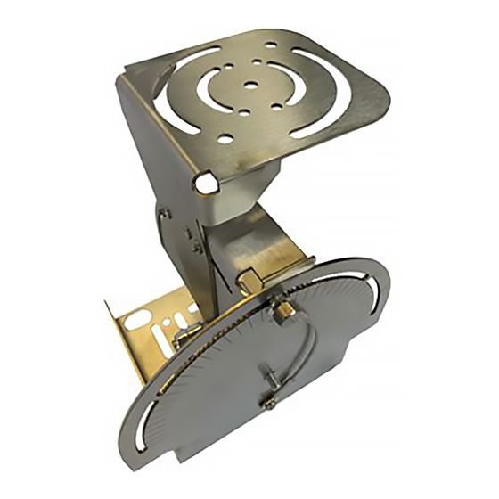
Quickstart Guide SP-Mount-1
Step 1
Mount part 1 to the desired surface.
Optimal height is between 10 and 20
feet. (Fig. 1)
Step 2
Mount the radar to part 3. Circular slots
can be used to change the roll of the
radar.
Step 3
Insert the stud on part 2 into the hole on
part 3 and attach the handle.
Step 4
Insert the stud on part 2 through the
hole in part 1 and attach the handle.
Step 5
Adjust to the desired angles and tighten
all positioning screws and handles. (See
back side for details)
TIP
Once the handle is threaded, pull
outward and the handle will rotate freely.
With the handle pulled out, a flathead
screwdriver can be used to tighten, if
needed.
Angular adjustment
instructions on back
WARNING:
When connecting Ethernet to
radar, always use grounded
shielded CAT5 cable.
Release Date: 05/23/2019
Rev.003
Part1
Part2
Optimal
mounting
Part3
height
Common
mounting
height
Radar can be
mounted lower
than 6' but range
performance is
decreased
Fig. 1
Radar Roll Adjustment:
Use these three
locations to mount
a C20, C40, CK2,
or CK10
Step 4
Step 3
Step 2
Fully Assembled
made from stainless steel and
locations to mount a
C550, C950, A2000,
4 5/16 in x 4 ¼ in
rust resistant parts
Use these four
or C1500
Advertisement
Table of Contents

Related Manuals for SpotterRF SP-MOUNT-8


Summary of Contents for SpotterRF SP-MOUNT-8
- Page 1 Quickstart Guide SP-Mount-1 Step 1 Mount part 1 to the desired surface. Step 4 Part1 Optimal height is between 10 and 20 feet. (Fig. 1) Part2 Step 2 Optimal Mount the radar to part 3. Circular slots mounting Part3 can be used to change the roll of the height radar.
- Page 2 Quickstart Guide SP-Mount-1 Yaw Angle Adjustment Pitch Angle Adjustment Hole Identification: Hole Identification: Part 3 Positioning hole Positioning hole Part 2 (extra securing hole - Offset hole aligns with positioning Offset hole (9° offset) hole) (9° offset) (covered by part 1 when assembled) (extra securing hole - (covered by part 2 aligns with offset hole)
Need help?
Do you have a question about the SP-MOUNT-8 and is the answer not in the manual?
Questions and answers