Advertisement
Table of Contents
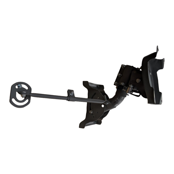
Quickstart Guide SP-Mount-RINO
Parts:
1.
Base Plate
2.
Stabilizing Arms
3.
Head Assembly
4.
Screws
5.
Radar Back
Housing*
• For sizes and
dimensions, visit our
Partner Portal at
www.spotterrf.com,
and information will
be found within the
Reseller Materials.
*Radar Back Housing will need to be custom fitted with 14mm nuts and bolts by SpotterRF.
Add-Ons:
1a.
Pole Mount
Brackets and
• Pole Mount Kit to be
Buckels (SP-
purchase separately.
MOUNT-RINO-
POLE-HW)
• Additional tools will be
2a.
Pole Mount Strap,
required (e.g. socket
Cinching Tool,
wrench, hammer, etc.)
and Industrial
Scissors (SP-
• Pole Mount Video
MOUNT-RINO-
Demonstration
POLE-TOOLS , SP-
available!
MOUNT-RINO-
POLE-BANDING)
Scan QR Code to
watch or contact
support@spotterrf.com
for details.
Release Date: 05/23/2019
Rev.002
1
2
3
4
5
1a
2a
Assembled Wall Mount
Fully Assembled Pole Mount
When connecting Ethernet to radar, always use
WARNING:
grounded shielded CAT5 cable.
1
Advertisement
Table of Contents

Related Manuals for SpotterRF SP-Mount-RINO


Summary of Contents for SpotterRF SP-Mount-RINO
- Page 1 Assembled Wall Mount and information will be found within the Reseller Materials. *Radar Back Housing will need to be custom fitted with 14mm nuts and bolts by SpotterRF. Add-Ons: Pole Mount Brackets and • Pole Mount Kit to be Buckels (SP- purchase separately.
- Page 2 Quickstart Guide SP-Mount-RINO Wall Mount Installation Install Base Plate with Attach Head Assembly Stabilizing Arms using to Radar Back Housing accompanied screws with the four custom onto wall at the desired fitted bolts and orientation. Ensure that associated nuts. Head...
- Page 3 Quickstart Guide SP-Mount-RINO Fine Tune Adjustments Fine Tune Adjustment Dials for Pitch and Yaw of the radar mount are indicated by the picture to the left (Pitch = Blue, Yaw = Red). Before you attempt to adjust these dials, make sure the associated nuts are loosened in the pictures below.
Need help?
Do you have a question about the SP-Mount-RINO and is the answer not in the manual?
Questions and answers