
Subscribe to Our Youtube Channel
Related Manuals for RCA Radiola 50


Summary of Contents for RCA Radiola 50
- Page 1 Radiola 50 REG, U.S. PAT, OFF. "AC " Socket-Powered 50 to 60 Cycles, 105 to 125 Volts INSTRUCTIONS IB-50 Radio Corporation of America 233 Broadway, New York City 100 West Monroe Street 235 Montgomery Street Chicago, 111. San Francisco, Cal.
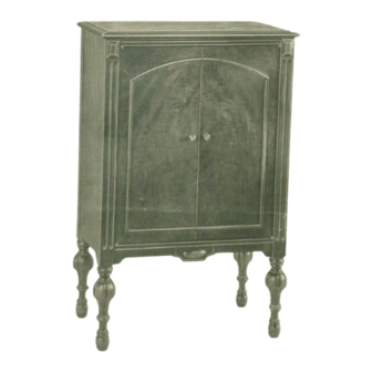
- Page 2 Fig. l—RCA Radiola 50...
- Page 3 Radiotron UX-171-A, in the final audio stage, in conjunction with the built-in RCA Loudspeaker 100-A. RCA Radiola 50 may be connected to any alternating-current circuit within the limits of 50 to 60 cycles and 105 to 125 volts. The socket-power unit, contained within the Radiola cabinet, furnishes alternating current to all filaments, as well as "B"...
- Page 4 , miniature base, 6 volts, 0.15 ampere. MAZDA One pilot lamp canopy. 2. One complete set of Radiotrons, as follows: Four RCA Radiotrons UX-226. One RCA Radiotron UY-227. One RCA Radiotron UX-171-A. One RCA Radiotron UX-280. 3. One 8-foot power cord with attaching plugs.
-
Page 6: Installation
INSTALLATION Preliminary—After removing RCA Radiola 50 from the shipping container, open the rear door. Unwrap the power cord and the antenna and ground leads. Plug the power cord into the bottom of the power connector, and see that the plug on the short cord from the Socket Power Unit is properly inserted at the top of the power connector, as shown in Figure 2. -
Page 7: Operation
" " the Power Switch. OPERATION To operate RCA Radiola 50, refer to Figure 4 and proceed as follows: 1. Set the Power Switch to the " " position. The pilot lamp should light. An interval of approximately 30 seconds is required for Radiotron UY-227 to heat before satisfactory reception is possible. - Page 8 Radiotrons will be obtained if the Voltage Switch (Figure 5) is set at the "110 V". position. To determine whether the supply is below 115 volts, consult the RCA Authorized Dealer or the Electric Light and Power Company. The Voltage Switch is accessible by removing the Terminal Cover (Figure 2). Before removing this Cover, the Power Switch (Figure 4) should be set in the "...
- Page 9 Fig. 6—RCA Radiola 50 Cabinet Wiring Antenna (a) Outdoor Type—A single-wire outdoor antenna, 25 to 50 feet long, will usually be sufficient for good reception. A short antenna is preferable in a locality where broadcast stations are numerous, whereas a longer antenna may give improved results in a locality distant from such stations.
- Page 10 The contact pins of the Radiotrons should be inspected occasionally and kept clean. It is a good plan to have available at least one new RCA Radiotron of each type. Periodically, the condition of each Radiotron in use should be checked by substituting a new one and comparing results in reception, both local and distant.
- Page 11 The RCA 90-day guarantee on this Radiola is not effective unless the RCA Guarantee Tag is countersigned at time of sale by the RCA Authorized Dealer from whom it was purchased. If you have not received the signed Guarantee Tag, be sure to have the RCA Authorized Dealer give it to you immediately.
- Page 12 STATION LOG Date Call Letters Location frequency in Wave Length Selector Dial Kilocycles Setting...
- Page 13 STATION LOG Date Call Frequen Wave Selector Location Letters cy in Length Dial Setting Kilocycl • . Printed in U.S.A.
Need help?
Do you have a question about the Radiola 50 and is the answer not in the manual?
Questions and answers