Advertisement
Quick Links
Advertisement

Subscribe to Our Youtube Channel
Related Manuals for CellarPro 6200VSi


Summary of Contents for CellarPro 6200VSi
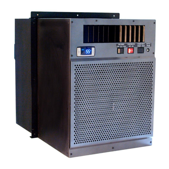
- Page 1 Control the Elements Owner’s Manual – 6200VSi / 6200VSx / 8200VSi / 8200VSx V9.14...
- Page 2 Website: www.cellarprocoolingsystems.com Serial Number* *We recommend that you take a minute to fill-in your CellarPro serial number above. The serial number has seven-digits and can be found on the printed label on the left side of your cooling unit. Don’t forget to register your cooling unit warranty at www.cellarpro.com/register...
-
Page 3: Table Of Contents
T a b l e o f C o n t e n t s Specifications and Cut Sheets Installation Instructions III. Operating Instructions Troubleshooting Limited Warranty V9.14... -
Page 4: Specifications And Cut Sheets
10.5A – 6200 16.1 x 33.1 x 21.9 (incl. 6200/8200VSi* rear duct hood & drain) 11.8A – 8200 16.1 x 31.8 x 21.9 6200/8200VSx (incl. exterior case & drain) * With optional rear duct hood 6200VSi / 8200VSi Cut Sheet V9.14... - Page 5 P l a c e m e n t CellarPro 6200 and 8200 Series cooling units are designed to be installed THROUGH THE WALL, so that the rear and the front of the cooling unit DO NOT SHARE THE SAME AIR SPACE.
- Page 6 20°F, and with our (optional) low ambient kit, all of our cooling units can be used in environments down to -20°F. CellarPro cooling units are not designed to heat the cellar space, so if temperatures inside the cellar drop below proper wine storage temperatures, the cooling unit cannot create heat inside the cellar.
- Page 7 - As the static load from ducting (if any) increases due to factors including the length of the duct run, turns, vent grills and/or reducers V e n t i l a t i o n Adequate ventilation is critically important for the proper operation of your CellarPro cooling unit. OUTSIDE THE CELLAR (At the rear of the cooling unit) Condenser Air Exhaust.
- Page 8 A surge-protected circuit is recommended. Set the power selector switch to energize the appropriate receptacle used (Front or Rear). The power cord provided for the model 6200VSi and 8200VSi is approved for indoor use only, while the power cord for model 6200VSx and 8200VSx may be used both for indoor or outdoor applications.
-
Page 9: Installation Instructions
II. Installation Instructions T E S T T H E U N I T B E F O R E I N S T A L L I N G I T 1. Remove the unit from the box. SAVE THE BOX AND PACKING MATERIALS. 2. - Page 10 Mount the unit in the upright position close to the ceiling inside the cellar. As warm air rises to the top of the cellar, the cooling unit pulls the warm air through the evaporator coil and removes the heat from the warm air. Once cooled, the cold air is discharged from the front of the cooling unit and circulates through the cellar.
- Page 11 6200 / 8200VS Installation Diagrams V9.14...
- Page 12 1/2 ” I.D. condensate drain line. The required hardware is shipped loose with the unit. a. Model 6200VSi / 8200VSi (indoor installations): Select the desired set of mounting holes, location #1, #2, #3, or #4 (shown above). The mounting brackets can be used on either side of the wall.
- Page 13 As shown above, the drain line should drop, then rise (but stay below the height of the fitting), and then drop again into a drain or bucket. Then, fill the trap with water. The condensate trap will allow any excess moisture inside the cooling unit to overcome the static pressure and flow out of the drain line.
- Page 14 racks. If measuring liquid, the probe in a bottle with water and rubbing alcohol (10- 20%), use the rubber stopper to seal the bottle, and place the bottle in the racks. If the bottle probe is used to measure air temperatures, the differential (HY) on the cooling unit should be set to “4”.
-
Page 15: Operating Instructions
These conditions include steady, cool temperatures, high humidity, minimal vibration and light, and clean air. The settings on your CellarPro cooling unit have been preset and optimized by the factory. Before changing any settings below, we recommend waiting 14 days to allow the cooling unit to “break in.”... - Page 16 T e m p e r a t u r e C o n t r o l CellarPro cooling units are designed to turn “on” when the air temperature passing over the evaporator coils inside the cellar exceeds the Minimum Set Point plus the Temperature Differential, and turn “off”...
- Page 17 S w i t c h I n s t r u c t i o n s Control Panel: Maintains desired cellar environment. Factory settings are optimized for peak performance. Controller is described in detail in the following section. Fan Speed Selector Switch (Low/High): The cooling unit fans operate on 2 speed settings: Low or High.
- Page 18 condensate is present at the overflow, the switch may be turned “off” to reduce unit energy consumption. For initial cellar pull down or in high humidity environments, the switch should be set to “on”. Power Selector Switch (Front/Rear): The unit is powered by installing the provided plug cord in the front or rear of the unit.
- Page 19 Press “Power” to turn the unit on and off. Power “On” / “Off” When the “Compr ess or On” indicat or ligh t is on, the Compress or is running. When the “Fan On” indicator light is on, the Fan is running. P le a s e no t e: T h e...
- Page 20 T o change t he Min i mum Set P oint , unt il °F” blinks T he “Set ” t emper at u re will blink t hr ee t imes to indicat e co nfirmat io n T he recom mend ed Minimum S et Point range is 53 - 60°F.
- Page 21 Remote Control / Display Instructions The temperature displayed on the control is red instead of blue. Digital Display To activate the “Quick Chill” mode, press the “Up” button for three seconds. Quick Chill Button To deactivate “Quick Chill”, press the “Up” button for three seconds again. The “Quick Chill”...
- Page 22 Advanced Operation CellarPro cooling systems can be programmed with advanced settings to achieve more control over conditions inside the cellar. Conditions like humidity, the Temperature Differential, and alarm settings all can be modified for custom applications. To access the advanced setti ngs, do the following: P r e s s t h e “...
- Page 23 Standard Protection Mechanisms The cooling unit is programmed to shut down certain components to protect those components, as well as the wine inside the cellar, under the following circumstances: Scenario What it means What happens P1 Alarm Probe 1, which senses the The cooling unit enters a temperature inside the cellar timed auto-cycle mode...
- Page 24 Please note : the temperature alarm (HA) is disabled during the first 23 hours of operation after the cooling unit is plugged in and/or turned on: Alarm Code What it means What to do Call CellarPro at 877.726.8496. P1, P3 Probe Failure The temperature Check if the cellar has a leak.
-
Page 25: Troubleshooting
Set Point. CellarPro 6200 and 8200 Series cooling units are designed to maintain proper wine storage temperatures inside cellars with adequate insulation up to 2200 cubic feet, depending on the cooling unit, thermal load and desired cellar temperature. - Page 26 If this alarm happens when you first receive and start operating your CellarPro cooling unit, check for appropriate installation and ventilation (Chapter II). Also, make sure that there aren’t any obstructions to the intake and/or exhaust vents. If your wine cabinet has a grill, remove the grill and/or any other obstructions above (top vent) or behind (back vent) the cellar.
-
Page 27: Limited Warranty
All service provided by CellarPro under the above warranty must be performed by a designated repair center, unless otherwise specified by C ellarPro. Purchaser is responsible for shipping the cooling unit to and from CellarPro or to and from a designated repair facility, and for removing and reinstalling the cooling unit from the wine cellar.
Need help?
Do you have a question about the 6200VSi and is the answer not in the manual?
Questions and answers